
DOI: 10.11817/j.issn.1672-7207.2016.12.014
�����Ե�����²�ͬ����ṹ�����������о�
������1, 2��������1
(1. ������ѧ ��·ʩ��������װ���������ص�ʵ���ң����� ������710064��
2. ���������豸������Ժ������ ������710065)
ժ Ҫ��
��������Ǻͼ�װˮƽ����2�ַ�ʽ����ƽ�����ṹ���иĽ�������2�ַ�ʽ�õ��IJ���ֱ���Ϊ������Ӳ��塣���벻ͬ����ṹ��Ե����ĸ��ʹ��Ƶ�3�������Ӳ�����������Եǰ�ƾ��룬��ƽ��ǰ�ƾ���ֱ�Ϊ56.8��114.6��187.8 mm���Լ�����Ϊ����������������Ƶ�����װ�ö�3�����ֱ���30��60��90 mm��3�ֲ�ͬ��������½����������������Ա����顣�о������������4������ļ���ṹ��������С�ڸ��Ӳ���ṹ����������������4�������2�ֲ���ṹ�������������ӽ�������1������ļ���ṹ�����������ƫ����ˣ��ڲ���������Ե����������£�����ֻ�������������������������̣����ü���ṹ���渴�Ӳ���ṹ�ǹ���ʵ������Ч���еİ취��
�ؼ��ʣ�
ƽ���������������Ե����������������������ˮƽ������
��ͼ����ţ�TU411 ���ױ�־�룺A ���±�ţ�1672-7207(2016)12-4056-06
Study on cutting resistance of different blade structures in condition of similar blade-edge
HE Yutian1, 2, LU Pengmin1
(1. Key Laboratory of Road Construction & Equipment of MOE, Chang��an University, Xi��an 710064, China;
2. Xi��an Special Equipment Inspection Institution, Xi��an 710065, China)
Abstract: The structures of flat blades were improved considering two ways of reducing the rake angle of the flat blade and adding horizontal plate, and the blades improved by the two ways were regarded as simple blade and complex blade, respectively. The concept of edge similarity among different blade structures was introduced, and three groups of simple blades and complex blades with average values of 56.8, 114.6 and 187.8 mm were designed. Based on self-designed testing apparatus, contrast tests under three different cutting depths of 30, 60 and 90 mm on grading soil were carried out to compare the cutting resistance. The results show that four groups of test��s cutting resistances of the simple blades are less than those of the complex blades, and other four groups of tests present a similar cutting resistance, and only one group of test��s cutting resistance of simple blade is higher than that of the complex blade. Therefore, it is an effective and feasible method that complex blades structure is replaced by simple ones in condition of different blades�� structures with similar blade-edge with only considering cutting resistance.
Key words: flat blade; dead zone; blade-edge; soil cutting; cutting resistance; horizontal plate
��ƽ���������������������У�����ǰ�˵��������Ƽ������»��γ�һ����������������ֻ��������ǽϴ�ʱ���ڣ���Ϊ�߽�Ш�Σ����߽С���������HETTIARATCHI��[1]�Ա߽�Ш�ε��γɺ���Բ���Ӧ���ֲ������Ӱ��������о���MIEDEMA[2]ָ���߽�Ш�β��Ǿ�̬�ģ������������Ի��Ե������������� WILLMAN��[3]ָ������ṹ��������������������ã���־����[4]�������崥�������������ƸĽ���̽�����������������ѽṹ��COETZEE��[5-6]����3�ֲ�ͬ�����Թ�������ڲ����е��������ɽ������о��������ڵĹ�������1��V����������������REN��[7]�������ֲڲ��������������⻬������жԱȣ�̽��������������ķ������²�[8]��������������������������������̬���������µ����������뵶�������ٶ�֮��Ĺ�ϵ�������о��������[9]�������������¸�������̬��Ϊ��������ɢ��Ԫģ�ͺ�����Աȷ�����ONO[10]������ɢ��Ԫģ�ͣ�ѡ��6�ֲ�ͬ��Ԫ��״����խƽ���������������Ӱ��������о������⣬һЩ���Ӽ��νṹ��������������о���������Ԫ����[11-12]��ƽ������������Ƕ���������������Ӱ��[13]��������Ǽ�С����������ƽ�������Ե������λ��ǰ�ƣ�Ϊ�ˣ��������߾Ͳ�����Ե������������λ����ͬ�����ʱ���������ı仯�����о���
1 ��������
�����������������ģ�ͽ϶࣬��ģ�;���һ�������÷�Χ������������ҵ�����IJ�ȷ�����ؽ϶࣬���ѽ���1���ձ����õ�ģ��[11]��������ģ�͵Ľ���������ڶ�����۲���ܽ�Ļ����ϵõ��ģ�Ϊ�˼�������̺����۷�����ͨ���������ڱȽϵIJ���ṹ��ƽ�������Ϊ��Ľṹ�������������Ķ�ά����άģ�ͽ����������о��нϳ���[12-14]��
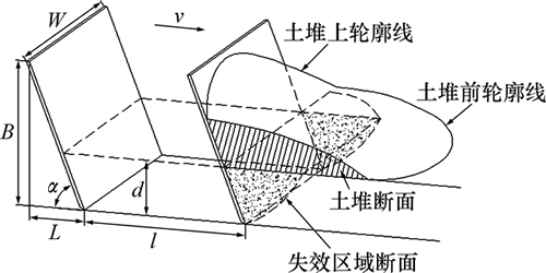
ͼ1��ʾΪƽ��������ά��������ģ�͡�ͼ1�У�WΪ������ȣ�BΪ��������������ͶӰ�ĸ߶ȣ�LΪ��Եǰ�ƾ��룻��Ϊ������ǣ�dΪ������ȣ�lΪ����λ�ƣ�vΪ�����ٶȡ������������̻ᾭ��2���Σ����������������ӽκ�������������ȶ��Ρ���ǰһ���������϶ѻ����ں�һ�������ѻ��ﵽ�ȶ�[19]��ͼ1�������������ѻ��ȶ��������ߣ��������ߵı�Ե�����������ߺ�ǰ�����߾����Ƴ������ߡ������������У����ڲ����������ѹ���ã�����������ʼ�մ���1��ʧЧ�档Ϊ�˸�ֱ�۵ر����������̣�ͼ1���������ز����Ķ���ͼ�����У�б����Ӱ����Ϊ���Ѷ��棬��״��Ӱ����ΪʧЧ������档���������ڲ���������������в���ǰ�ƣ��������ѻ�������ʧЧ�������������γɵġ�
��ͼ1���Կ������Դ�ֱƽ��Ϊ�ο���������Եλ�����������һһ��Ӧ�����߹�ϵʽΪ
L=B��cot�� (1)
��ʽ(1)��֪������ƽ�������Եǰ�ƾ���ȷ������ƽ�������������Ҳ��ȷ���ġ���ȷ������������£�������Եǰ�ƾ���Խ���������ԽС���������������ʱ����Եǰ�ƾ�����С����ʱ��ͨ����װˮƽ������Ի���������Ե����������ͼ1��ʾƽ����壬������ı�ɸ�ΪB��ˮƽ����ΪL��ֱ�Dz��壬��ֱ�Dz�����ƽ��������Եǰ�ƾ�����ͬ��������ṹ�����˸ı䡣
ͼ1 ��������ģ��
Fig. 1 Soil cutting model
2 �������
2.1 ����ṹ
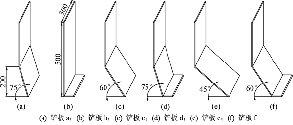
�Բ��������6�ֽṹ��ʽ����ͼ2��ʾ����6�ֲ���ṹ�����������ϵ�ͶӰ��ͬ����Ϊ500 mm����Ϊ300 mm��������b���⣬����5�ֲ�����ھ���Ե����ƽ���200 mm���������䣻�Ҳ���b������ƽ��ļн�Ϊ90�㣬����a��d������ƽ��ļнǾ�Ϊ75�㣬����c��f������ƽ��ļнǾ�Ϊ60�㣬����e������ƽ��ļн�Ϊ45�㣻ƽ���������75���õ�����a����ֱ�����װˮƽ������õ�����b������a��װˮƽ�����õ�����d������c��װˮƽ�����õ�����f��6�������������Ե�봹ֱ������Ⱦ���ǰ���죬Ϊ��ʹ����a��b������c��d�Լ�����e��f����Ե�������ǰ�ƾ��룬�������װˮƽ���������ơ�
����Ե�봹ֱ���������ǰ�������ֱ�ΪLa��Lb��Lc��Ld��Le��Lf������a��c��e����ֱ�������������Եǰ�ƾ�����ʽ(1)�ɵã�La��53.6 mm��Lc��115.5 mm��Le=200 mm�����ݲ���ṹ�ص㣬Ϊ���㿪չ���飬������b��d��e��װ��ˮƽ����ij��Ⱦ����Ϊ60 mm�������b��d��e����Եǰ��ֵ�ֱ�Ϊ��Lb=60.0 mm��Ld��113.6 mm��Lf��175.5 mm����ʱ������a��b������Եǰ�ƾ���ľ��Բ�ֵԼΪ6.4 mm������c��b������Եǰ�ƾ���ľ��Բ�ֵС��2.0 mm������e��f������Եǰ�ƾ���ľ��Բ�ֵ�Դ�ԼΪ24.5 mm��3�����������Եǰ�ƾ���ƽ��ֵ�ֱ�Ϊ56.8��114.6��187.8 mm���Բ���������Եǰ�ƾ���ƽ��ֵΪ�ο�������a��b������c��d�Լ�����e��f��3������ǰ�ƾ���ʵ��ֵ��ο�ֵ�����ֱ�Ϊ5.6%��0.08%��6.5%���ӹ���Ӧ�ýǶȿ���������Աȵ�Ҫ����ˣ���������3��������Եǰ�ƾ�������IJ�����жԱ������о�����������a��c��e��Ϊ�ṹ������b��d��f��Ϊ���ӽṹ��
ͼ2 ����ṹ
Fig. 2 Blades structures
2.2 ������������
������������50%��ɰ��20%��ɰ��30%�������ɵļ���������ˮ��Ϊ5.5%���ң��ܶ�Ϊ1.5~1.7 g/cm3��
2.3 �������
�Ա��������������Ƶ���קʽ��������װ���Ͻ��С������ٶ�����Ϊ0.12 m/s��ѡ��3�ֲ�ͬ������ȣ��ֱ�Ϊ30��60��90 mm��
3 ������
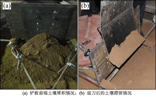
ͼ3��ʾΪ����������������̣�����ǰ�����ѻ��Ƚ��ȶ��Ҿ���һ������(��ͼ3(a))��������ɺ������˳�����ˮƽ�����IJ�������������������������ڲ����ڴ��������¶���������ʱ�����1����������[1]�������ò�������ˮƽ�������ڣ���Ϊ������1���������������������������ΪШ�ο����ʽ(��ͼ3(b))��
6�ֲ���(����a��b��c��d��e��f)�ֱ���3�ֲ�ͬ��������£�������18�������������顣3������ڲ�ͬ��������µ����������仯���߷ֱ���ͼ4~6��ʾ��
ͼ3 ������������
Fig. 3 Soil cutting processes
4 �Աȷ���
��ͼ4~6�ɿ������������������˴������ӵ������ȶ���2���Σ���������������λ�ƴ�700 mm������ȶ�����ˣ��ڶԱȷ����У���������Ϊ����λ�ƴ���700 mmʱ��ƽ��ֵ��
3������ڲ�ͬ��������µ�ƽ�����������Աȼ�ͼ7����ͼ7(a)�ɼ������������Ϊ30 mmʱ������a��b�����������ֱ�Ϊ0.404 kN��0.365 kN������b�����������Dz���a��90.4%�����������Ϊ60 mmʱ������a��b�����������ֱ�Ϊ0.828 kN��0.757 kN������b�����������Dz���a��91.4%�����������Ϊ90 mmʱ������a��b�����������ֱ�Ϊ1.766 kN��1.182 kN������b�����������Dz���a��67.0%���Ӳ���a�Ͳ���b�����������Աȿ��Կ���������b�������������Ȳ���a��С���������������������Ϊ30 mm��60 mmʱ�Ͻӽ�����������ȴﵽ90 mmʱ������b�������������ԱȲ���a��С��
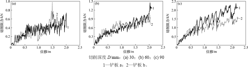
ͼ4 ����a��b�����������仯����
Fig. 4 Curves of cutting resistance for blades a and b
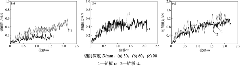
ͼ5 ����c��d�����������仯����
Fig. 5 Curves of cutting resistance for blades c and d
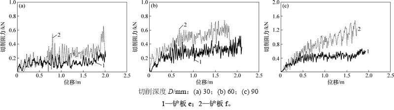
ͼ6 ����e��f�����������仯����
Fig. 6 Curves of cutting resistance for blades e and f
��ͼ7(b)�ɼ������������Ϊ30 mmʱ������c��d�����������ֱ�Ϊ0.152 kN��0.344 kN������c����������ԼΪ����d��44.0%�����ߵ������������ڽϴ���죻���������Ϊ60 mmʱ������c��d�����������ֱ�Ϊ0.453 kN��0.437 kN�������ӽ������������Ϊ90 mmʱ������c��d�����������ֱ�Ϊ0.943 kN��0.942 kN�������൱���ԱȲ���c�Ͳ���d���������������ߵĴ�С��һ���ԣ������������Ϊ60 mm��90 mmʱ����������������Ϊ����ȫһ�µġ�
��ͼ7(c)�ɼ������������Ϊ30 mmʱ������e��f�����������ֱ�Ϊ0.149 kN��0.255 kN������e����������ԼΪ����f��58.7%�����������Ϊ60 mmʱ������e��f�����������ֱ�Ϊ0.330 kN��0.540 kN������e����������ԼΪ����f��61.0%�����������Ϊ90 mmʱ������e��f�����������ֱ�Ϊ0.478 kN��0.928 kN������e����������ԼΪ����f��51.6%������3������£�����e�������������Ȳ���f��С��������Ϊ����f�����������У�����ˮƽ�����Ĵ��ڻ���Ϊ�����ڲ���ǰ���γɲ��������������������ԡ����������ѻ�����������������������������
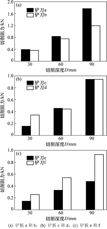
ͼ7 3������ڲ�ͬ��������µ�ƽ�����������Ա�
Fig. 7 Comparison of average cutting resistance for three groups of blade under different cutting depths
5 ����
�����3�鼸�����νṹ����һ������IJ��壬�乲ͬ�����Dz�����Ե��ǰ�ƾ�������������3���������������6�ֲ�ͬ�ṹ���������������顣������������
1) �Բ���a�Ͳ���b�����������Ϊ30 mm��60 mmʱ�������������첻�����������Ϊ90 mmʱ������a�����������Ȳ���b�ĴԲ���c�Ͳ���d�����������Ϊ30 mmʱ������c�����������Ȳ���d��С��������2����������£���������ƽ��ֵ����������Բ���e�Ͳ���f����3����������£�����e�����������������Ȳ���f��С��
2) �ۺϱȽ�3�����Ľṹ������Եǰ��ֵ����������£�������a��c��e�Ľṹ�ֱ������b��d��f�Ľṹ���бȽϣ�����a��c��e�Ľṹ��Լ�������9��Ա������У�ֻ��1������ṹ�������������Աȸ��ӽṹ�Ĵ�4��������������������ӽ�������4��ṹ�������������Աȸ��ӽṹ��С����ˣ��ڽ�������������е�IJ���ṹ���ʱ��������ṹ����Ե�ߴ�ȷ���������£�ѡ��ṹ��ԼIJ��壬��һ�������¿�������С��������������Ե��������������������ʱ��Ҳ����ʹ�ü���ṹ���������ټӹ�����ijɱ������ҿ����㹤��ʵ����Ҫ��
�ο����ף�
[1] HETTIARATCHI D R P, REECE A R. Boundary wedges in two dimensional passive soil failure[J]. Geotechnique, 1975, 25(2): 197-220.
[2] MIEDEMA S A. The cutting mechanisms of water saturated sand at small and large cutting angles[C]//International Conference on Coastal Infrastructure Development-Challenges in the 21st Century. Hong Kong, China, 2004: 1-14.
[3] WILLMAN B M, BOLES W W. Soil-tool interaction theories as they apply to lunar soil stimulant[J]. J Aerosp Eng, 1995, 8(2): 88-99.
[4] ��־��, �Ÿ�, ������, ��. ����������ʽ���������������Ӱ�����������[J]. ũҵ��еѧ��, 2015, 46(7): 372-378.
GUO Zhijun, DU Gan, LI Zhongli, et al. Orthogonal experiment on resistance reduction by soil-engaging surfaces of bulldozer blade[J]. Transactions of the Chinese Society for Agricultural Machinery, 2015, 46(7): 372-378.
[5] COETZEE C J, BASSON A H, VERMEER P A. Discrete and continuum modelling of excavator bucket filling[J]. Journal of Terramechanics, 2007, 44(4): 177-186.
[6] COETZEE C J, ELS D N J. The numerical modelling of excavator bucket filling using DEM[J]. Journal of Terramechanics, 2009, 46(5): 217-227.
[7] REN L Q, HAN Z W, LI J Q, et al. Experimental investigation of bionic rough curved soil cutting blade surface to reduce soil adhesion and friction[J]. Soil & Tillage Research, 2006, 85(4): 1-12.
[8] �²�. ������̬�����������о�[J]. ��·��е��ʩ����е��, 2000, 17(2): 11-13.
CHEN Bo. Experimental study of soil dynamic cutting[J]. Road Machinery & Construction Mechanization, 2000, 17(2): 11-13.
[9] ����, ���, ������, ��. �����������ǶԸ�������̬��ΪӰ�����ɢԪģ��[J]. ���ִ�ѧѧ��(��ѧ��), 2007, 37(4): 822-827.
ZHANG Rui, LI Jianqiao, XU Shucai, et al. Simulation on dynamic behavior of dry soil ahead of the bulldozing plate with different cutting angles by DEM[J]. Journal of Jilin University (Engineering and Technology Edition), 2007, 37(4): 822-827.
[10] ONO I, NAKASHIMA H, SHIMIZU H, et al. Investigation of elemental shape for 3D DEM modeling of interaction between soil and a narrow cutting tool[J]. Journal of Terramechanics, 2013, 50(4): 265-276.
[11] ARMIN A, FOTOUHI R, SZYSZKOWSKI W. On the FE modeling of soil-blade interaction in tillage operations[J]. Finite Elements in Analysis and Design, 2014, 92(24): 1-11.
[12] IBRAHMI A, BENTAHE H, HBAIEB M, et al. Study the effect of tool geometry and operational conditions on mouldboard plough forces and energy requirement: Part 1. Finite element simulation[J]. Computers and Electronics in Agriculture, 2015, 117(9): 258-267.
[13] KOBAYASHI T, OCHIAI H, FUKAGAWA R, et al. A proposal for estimating strength parameters of lunar surface from soil cutting resistances[C]//10th Biennial ASCE International Conference on Engineering, Construction, and Operations In Challenging Environments (Earth and Space 2006). Houston, 2006: 1-8.
[14] JAYASURIYA H P W, SALOKHE V M. A review of soil tine models for a range of soil conditions[J]. J Agric Engng Res, 2001, 79(1): 1-13.
[15] ALUKO1 O B, CHANDLER H W. Characterisation and modelling of brittle fracture in two-dimensional soil cutting[J]. Biosystems Engineering, 2004, 88(3): 369-381.
[16] MALAGUTI F. Soil machine interaction in digging and earthmoving automation[C]//Proceedings of the 11th International Symposium on Automation and Robotics in Construction. Brighton, 1994: 187-192.
[17] ½����. ������������������õ�ճ����������Ԫ����[J]. ��ľ����ѧ��, 2002, 35(6): 17-81.
LU Huaimin. Finite element analysis for the interaction of soil cutting part and soil[J]. China Civil Engineering Journal, 2002, 35(6): 17-81.
[18] OBERMAYR M, VRETTOS C, EBERHARD P, et al. A discrete element model and its experimental validation for the prediction of draft forces in cohesive soil[J]. Journal of Terramechanics, 2014, 53(4): 93-104.
[19] YANG Qinsen, SUN Shuren. A soil-tool interaction model for bulldozer glades[J]. Journal of Terramechanics, 1994, 31(2): 55-65.
(�༭ �²ӻ�)
�ո����ڣ�2016-01-10�������ڣ�2016-03-22
������Ŀ(Foundation item)�����ҿƼ�֧�żƻ���Ŀ(2015BAF07B02)(Project(2015BAF07B02) supported by the National Key Technology R&D Program of the Ministry of Science and Technology of China)
ͨ�����ߣ�������ʿ����ʦ�����ڣ����»�е��̬�������Ż���Ƽ��ṹ��ƣǿ����ɿ����о���E-mail��lpmin@chd.edu.cn
ժҪ����Լ�Сƽ�����������Ǻͼ�װˮƽ����2�ַ�ʽ����ƽ�����ṹ���иĽ�������2�ַ�ʽ�õ��IJ���ֱ���Ϊ������Ӳ��塣���벻ͬ����ṹ��Ե����ĸ��ʹ��Ƶ�3�������Ӳ�����������Եǰ�ƾ��룬��ƽ��ǰ�ƾ���ֱ�Ϊ56.8��114.6��187.8 mm���Լ�����Ϊ����������������Ƶ�����װ�ö�3�����ֱ���30��60��90 mm��3�ֲ�ͬ��������½����������������Ա����顣�о������������4������ļ���ṹ��������С�ڸ��Ӳ���ṹ����������������4�������2�ֲ���ṹ�������������ӽ�������1������ļ���ṹ�����������ƫ����ˣ��ڲ���������Ե����������£�����ֻ�������������������������̣����ü���ṹ���渴�Ӳ���ṹ�ǹ���ʵ������Ч���еİ취��
