J. Cent. South Univ. (2012) 19: 623-632
DOI: 10.1007/s11771-012-1048-8
Crawlspace heating system in detached house with insulated foundation
LIU Qing-rong(刘青荣)1, RUAN Ying-jun(阮应君)2, RYU Yu-ji3, REN Jian-xing(任建兴)1
1. Institute of Energy and Environmental Engineering, Shanghai University of Electric Power,Shanghai 200090, China;
2. School of Mechanical Engineering, Tongji University, Shanghai 200092, China;
3. Faculty of Environment Engineering, The University of Kitakyushu, Kitakyushu 808-0135, Japan
? Central South University Press and Springer-Verlag Berlin Heidelberg 2012
Abstract: Two practical crawlspace heating systems introduced in detached houses have been chosen as a field study. One is the crawlspace warm air heating system and the other is the crawlspace hot water circulation system. Based on the field study result, by using the simulation software, THERB, the effectiveness of the crawlspace warm air heating system has been examined. The effect of the factors, such as the wind amount circulating between crawlspace and indoor space, foundation insulation condition, and heat amount into the crawlspace, on the indoor thermal environment has been analyzed. Based on these analyses, the measured crawlspace heating system can make the average temperature of the living room above 20 °C. These two houses have excellent thermal environment. According to the simulating result, heat amount input into crawlspace, which can make comfortable indoor thermal environment, for every month in heating period has been roughly concluded, and they are 600 W in December and March and 800 W in February and January, respectively.
Key words: crawlspace heating system; indoor thermal environment; detached house; floor insulation; foundation insulation
1 Introduction
In order to improve the comfort of the indoor thermal environment and decrease the energy consumption, the insulated and airtight houses are widely adopted in detached houses. They are characterized by temperature uniformity and little heat loss. Therefore, insulation and air-tightness are worth introducing into building or remodeling a house.
In Japan, the insulating method of the bottom in the detached house has two types: floor insulation and foundation insulation. In the insulated floor house, the crawlspace under the floor is open to outside. Conversely, the crawlspace is airtight space in the insulated foundation house. Compared with the insulated floor house, the insulated foundation house has easier construction. At the same time, the crawlspace can be utilized as the heat conveyance part and thermal storage part for heating or cooling system. Currently, there are some researches regarding the thermal environment of the crawlspace in the detached house. HONMA et al [1-2] analyzed the hygrothermal environment of the crawlspace in winter and in summer including rainy season for the moderate and humid climate region. FUKUSHIMA et al [3] examined the application of passive ventilation system with crawlspace heating to the practical house in cold region. KYU et al [4] presented an emulation method to evaluate the control performance of a hydronic radiant heating system. JIN et al [5] built a numerical model for the radiant floor cooling system using finite volume method. Some researchers analyzed the thermal comfort in radiant heating system [6-10]. MAXIME [11] determined an optimal modeling method for heat transfer calculation of low thermal mass hydronic radiant cooling or heating panels with serpentine tube layout. CAUSONE et al [12] evaluated the heat transfer coefficients between radiant ceiling and room in typical conditions. TIAN and LOVE [13] presented the findings of a field study of occupant thermal comfort and thermal environments with a radiant slab cooling system. Other researchers analyzed air temperature by computational fluid dynamics (CFD) in radiant systems [14-17].
However, few researches have been conducted on the effectiveness of the crawlspace heating and cooling system for the moderate and humid climate region. In this work, we evaluated the thermal environments in the living room and crawlspace for two practical crawlspace heating systems by using the measured data. One is the crawlspace warm air heating system and the other is the crawlspace hot water circulation system. According to the results, the existing problems of crawlspace heating system have been clarified. In order to deal with the problems, the crawlspace warm air heating system is modeled for a foundation insulation detached house located in Fukuoka, Japan. By using the simulation software, THERB, the effectiveness of the crawlspace warm air heating system was examined and the effects of the factors were evaluated. Furthermore, based on the simulation result, the energy amount for crawlspace heating system, which can make the indoor thermal environment comfortable enough for every month in heating period, can be roughly calculated.
2 Outline of measurement on crawlspace heating system in practical detached houses
2.1 Outline of crawlspace heating system and detached houses
The details of these two detached houses are shown in Table 1. From Table 1, it can be found that the insulation level of exterior wall is three in House 1 and it is four in House 2 evaluated according to the Housing Performance Display System in Japan. The heating system is different. In House 1, it is a crawlspace warm air heating system and a hot water circulation pipe system in crawlspace is adopted in House 2. The details of insulation, air-tightness and heating system of these two houses are introduced. Figure 1 shows the cross section of crawlspace and heating system and the photograph of warm air duct in House 1 and Fig. 2 shows the cross section of crawlspace and heating system and the photograph of hot water pipe in House 2. The first floor plans of House 1 and House 2 are shown in Fig. 3 and Fig. 4, respectively.
House 1 was completed in Dec. 1995. It is an environmental symbiosis house with passive and active devices, such as PV system, direct heat gain, and cool tube. In this house, a conventional insulation method has been adopted. The 100 mm glass wool was used as the insulation material for exterior wall and ceiling. The 25 mm styrene board was used for interior insulation of roof. Single plate glass has been installed for windows. The insulation method of foundation wall is interior insulation type. The foundation wall and the dampproof concrete in the crawlspace are all covered with insulation material, namely, 25 mm styrene board. Furthermore, in the south floor of the living room, concrete has been placed for collecting solar-radiance directly and its surface was covered with the tile.
Table 1 Outline of measurement detached houses
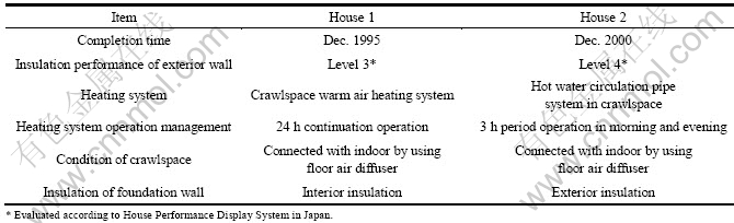
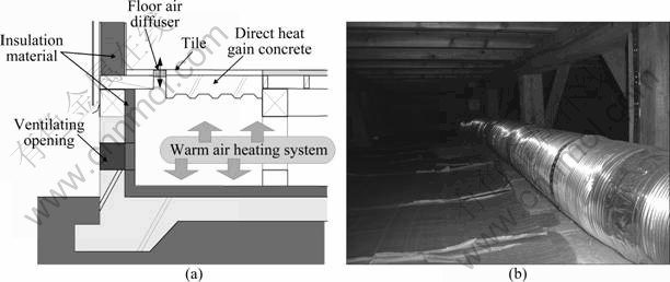
Fig. 1 Cross section of crawlspace and heating system (a) and photograph of warm air duct (b) in House 1
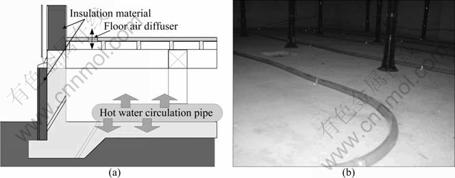
Fig. 2 Cross section of crawlspace and heating system (a) and photograph of hot water pipe (b) of House 2
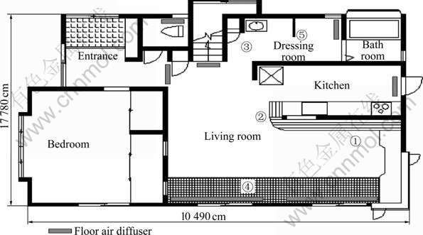
Fig. 3 First floor plan and measurement point in House 1
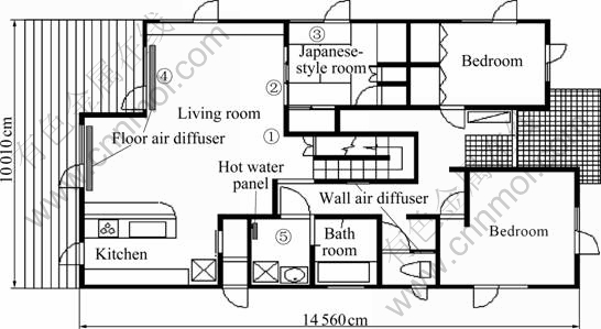
Fig. 4 First floor plan and measurement point in House 2
The heating system of House 1 is the crawlspace warm air heating system. It is 24 h continuation operation. In order to make excellent heat diffusion from crawlspace to indoor space, the floor air diffusers have been installed, as shown in Fig. 3. The warm air can also be blown into living room through these diffusers, so the air is ventilated between crawlspace and indoor space. Figure 1(b) shows the warm air duct in crawlspace.
House 2 was completed in Dec. 2000. The 100 mm fiber insulation material was put in the exterior wall. The roof was insulated with 100 mm fiber insulation material and 50 mm polystyrene board. The pair-glass and wooden sash were used in window to insulate and seal. House 2 has the foundation insulated from the outside. The insulation material is 60 mm styrene form.
As for the heating system, the hot water pipes have been laid above the foundation dampproof concrete in the crawlspace at the appropriate interval. And the operation mode is 3 h operation at morning and evening. The concrete is also used as the thermal storage part for the heating system. The floor air diffusers are located at the perimeter of the living rooms. However, different from House 1, the wall air diffusers are also installed in the wall of the toilet and corridor. By natural convection, the air is ventilated between crawlspace and indoor space. Figure 2(b) displays the hot water pipes in crawlspace.
2.2 Measurement method
The thermal environmental measurement was carried out from Nov. 2002 to Mar. 2004. The measurement items are: 1) temperature and relative humidity of living room; 2) temperature and relative humidity in the center of crawlspace; 3) temperature in the north portions of crawlspace; 4) temperature in the south portions of crawlspace; 5) temperature and relative humidity of dressing room. These data were recorded at 10 or 30 min interval. The measurement sites in these two houses are shown in Fig. 3 and Fig. 4 with the numbers.
In this work, the recorded data from Dec. 2003 to Mar. 2004 were used for the thermal environment analysis. In the process of analyzing, the air temperature of crawlspace is the average value of center, south and north measured air temperatures of crawlspace.
3 Measurement data analysis
3.1 Thermal environment
The recorded data from Dec. 1st, 2003 to Mar. 31st, 2004 were used for analysis.
Figure 5 displays the thermal environment of crawlspace and Fig. 6 displays the thermal environment of living room. The temperature in these figures is the daily average temperature. From Fig. 5, the majority of the temperature was covered in the range of 23-26 °C in House 1. Because on 14th and 15th in March, the heating system was not operated for some reason, there were two data about 16 °C. And few of low temperature also existed, because the heating system was not operated for 24 h. The operating time of the boiler for the heating system in House 2 is set to be 3 h in morning and evening, so the temperature would be lower in the non-operation time. However, because of thermal storage effect of the concrete, the temperature was still higher than 20 °C.
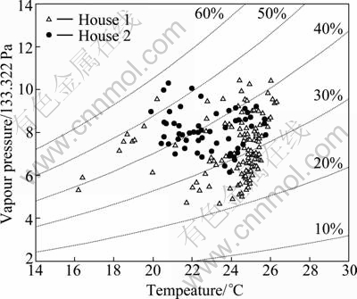
Fig. 5 Daily thermal environment of crawlspace
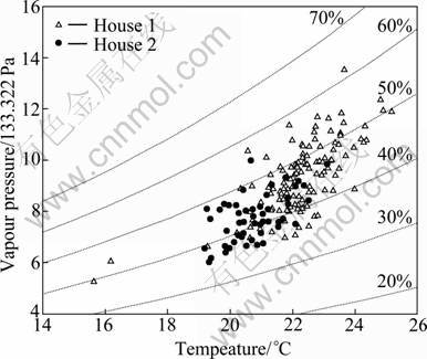
Fig. 6 Daily thermal environment of living room
As Fig. 6 shows, the temperature of living room in House 1 was higher than that in House 2, and it changes about 22 °C. In House 2, the majority of the living room temperature was covered in the temperature range of 20-22 °C. And the stability of the living room temperature was able to be verified in these two houses.
The average temperature of crawlspace in House 1 was 24.0 °C, higher than that (22.8 °C) in House 2. The lowest value of crawlspace and living room were 15.0 and 13.9 °C which occurred on March 15th (the non- operation day). Although the operation time is only 3 h in morning and evening, the lowest temperature of crawlspace was still 19.5 °C in House 2, because of the thermal storage effect and the excellent thermal insulation performance. The average temperature of living room in House 1 was 22.2 °C and it was 20.8 °C in House 2.
3.2 Hourly temperature fluctuation
The temperature fluctuation of House 1 for two days (Feb. 27th and 28th, 2004) is shown in Fig. 7 and the temperature fluctuation of House 2 for two days (Feb. 27th and 28th, 2004) is shown in Fig. 8.
For the 24 h continuation operation of the crawlspace warm air heating system in House 1, the temperature of crawlspace was stable at about 24 °C. And the living room had the excellent thermal environment for the temperature was almost higher than 20 °C in House 1. However, the dressing room temperature was lower, and the lowest temperature was lower than 16 °C in this room. In House 2, the rise of crawlspace temperature was remarkable when the heating system was operated in morning and evening. The boiler operation is controlled by the temperature sensor (set in kitchen) in House 2. When the temperature is higher than a certain value, the hot water boiler is not operated. So, the crawlspace temperature did not rise in the morning of the 28th, for the hot water boiler was not operated. The maximum temperature of crawlspace reached about 27 °C, and the temperature of the living room and dressing room fluctuated similarly within the range of 18-20 °C.
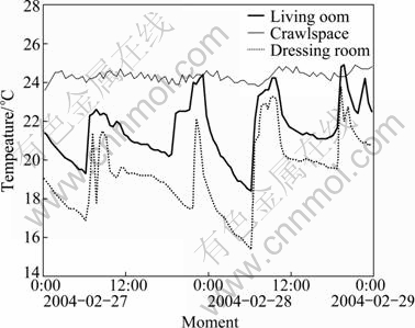
Fig. 7 Temperature fluctuation of House 1 in two days
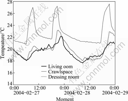
Fig. 8 Temperature fluctuation of House 2 in two days
4 Outline of simulation
According to the measurement, it can be found that the crawlspace heating system is effective in the practical application for the detached house. Based on the results, the air circulation between crawlspace and indoor space, the foundation condition, existence of thermal storage in crawlspace, heat amount supplied into crawlspace are the important factors to influence the indoor thermal environment. In order to clarify these problems, the simulation on the crawlspace warm air heating system was done by using the simulation software, THERB. Figure 9 shows the concept diagram of the crawlspace warm air heating system. In this work, the warm air is diffused to the crawlspace averagely. Also, the warm air in crawlspace is diffused to indoor space through the floor air diffuser. Indoor air returns to crawlspace through the opening on the interior wall. The heat can also diffuse to indoor space through thermal transfer.
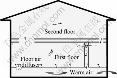
Fig. 9 Crawlspace warm air heating system
4.1 Outline of detached house for simulation
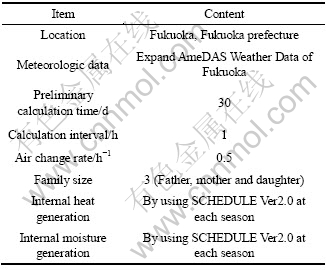
The practical detached house located in the Fukuoka, Japan, was used for the simulation. Figures 10 and 11 display the first floor and second floor plan, respectively. The floor air diffusers for the simulated crawlspace heating system are also displayed in Fig. 10. Table 2 gives the building materials for the exterior structures of this detached house. The interior insulation was adopted in foundation wall. The heat loss coefficient of this detached house is 1.66 W/(m2・K), lower than the standard value of 2.7 W/(m2・K) provided in the Next-generation Energy Saving Standard for the IV regions of Japan. The basic condition for simulation is concluded in Table 3. The meteorologic data for simulation were the standard year data of the Expanded AMeDAS Weather Data for Fukuoka, Japan. The simulation period is January, the coldest month. Hourly thermal environment data were calculated. For the practical residence, the internal heat and moisture generation is estimated by using the SCHEDULE Ver2.0 (Life Schedule Operation Generator proposed by the Society of Heating Air-conditioning and Sanitary Engineers of Japan). The internal heat and moisture generation is considered as the already known condition input into the program. The internal heat generation is taken as the good factor for the thermal environment.
4.2 Details of simulation cases
Eight cases were set for simulation considering the floor air diffuser, foundation insulation condition and heat amount. Table 4 gives the details of the simulation cases. In cases 1-4, the foundation is insulated and concrete above insulation layer is used for thermal storage. However, the floor air diffusers are not set for the warm air circulations in Case 1. In cases 2-4, three floor air diffusers are set. The characteristics of these floor air diffusers are concluded in Table 5. The aperture rate of the floor air diffuser is assumed as 50%. According to the aperture area and wind velocity, the wind amount circulating between crawlspace and indoor space for cases 2-4 is calculated and displayed in Table 6. The circulation wind amount of Case 5 and Case 6 is the same as Case 4. The insulation condition of Case 5 is also the same as Case 4, but the concrete is not set above the insulation layer for thermal storage in Case 5. As for the foundation condition in Case 6, foundation wall and the perimeter part about 1 m in width from foundation wall is insulated and damp proof concrete above ground is used for thermal storage part. The floor air diffusers and foundation condition of Case 7 and Case 8 are the same as Case 6. However, the heat amount supplied into crawlspace is different. In Case 6, the heat amount is 1 000 W, and 800 W in Case 7, and 500 W in Case 8.
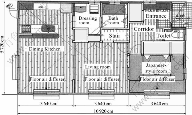
Fig. 10 First floor plan of detached house
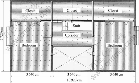
Fig. 11 Second floor plan of detached house
Table 2 Building materials for structure
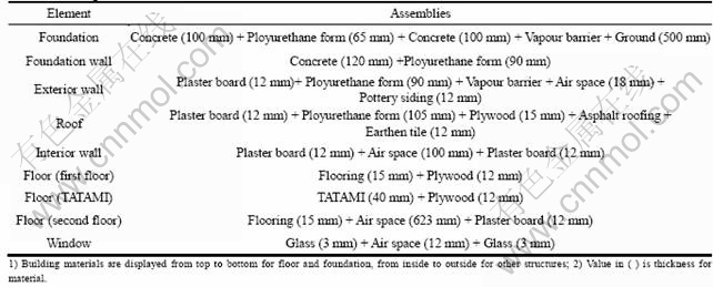
Table 3 Basic conditions of simulation
5 Simulation data analysis for affection factors
5.1 Effect of circulation wind amount
According to the simulation results, living room temperature is higher than 20 °C except on Jan. 19th- 23rd. Hourly temperature fluctuations (Jan. 19th and 20th which are the coldest days) of living room for cases 1-4 with different circulation wind amounts are shown in Fig. 12. However, the hourly temperature in Case 4 is also higher than 20 °C. In Case 4, the lowest temperature can reach 18.7 °C. The highest living room temperature occurs in Case 4 with the largest circulation wind amount. It can be found that the increase of the wind amount can improve the indoor air temperature.
The average temperature of cases 1-4 for January is listed in Table 6. It can be found that the air and ground surface temperatures in crawlspace fall with increasing the circulation wind amount. However, the increase of wind amount can make the temperature of living room and bedroom on the second floor rise. In Case 4, the average temperature of living room is 22.7 °C, and bedroom temperature on the second floor is 17.9 °C. The first floor surface temperature is 23.0 °C. Based on above simulation results, Case 4 with the largest circulation wind amount can gain comfortable thermal environment than cases 1-3.
Table 4 Details of simulation cases
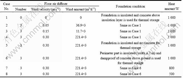
Table 5 Details of floor air diffuser

Table 6 Average temperature of cases 1-4
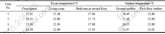
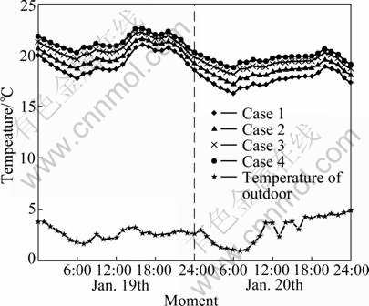
Fig. 12 Hourly temperature fluctuations of cases 1-4
5.2 Effect of foundation insulation condition
Figure 13 displays hourly temperature fluctuations (Jan. 19th and 20th) of cases 4-6. According to the simulation results, in Case 5, the temperature of living room is the lowest among these three cases, especially for the period with the lowest outside temperature. The reason is that thermal storage has not been designed in Case 5. In Case 4, although there is concrete set for thermal storage, the living room temperature in the coldest period is lower than that in Case 6, for the concrete is above the insulation layer which cannot utilize the excellent thermal condition of ground. In Case 6, the insulation material is laid on the foundation wall and the perimeter part of the foundation with 1 m in width, and the concrete is laid directly above the ground for the thermal storage part. So, the stable thermal condition of ground can be utilized. On Jan. 19th-23th, the daily average temperature of living room can almost reach 20 °C. From hourly temperature fluctuations, in Case 6, the living room can make excellent thermal environment with the lowest temperature of 19 °C at 6:00.
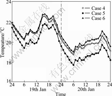
Fig. 13 Hourly temperature fluctuations of cases 4-6 with different foundation conditions
Based on the results about foundation insulation condition, the design considering both the adoption of thermal storage part and the utilization of the stable thermal condition of ground is useful for the crawlspace heating system.
5.3 Effect of heat amount supplied into crawlspace
According to the analysis of Section 5.1 and 5.2, in Case 6, the temperature of living room occurs overheat for the temperature is higher than 26 °C in some periods. In order to get the most comfortable thermal environment with the least energy, Case 7 and Case 8 are set for simulation. In Case 7, the hourly heat amount input to crawlspace is 800 W and it is 500 W in Case 8. Hourly temperature fluctuations (Jan. 19th and 20th) of living room for cases 6-8 are shown in Fig. 14. It can be found that the lowest temperature in Case 7 is also about 18 °C. The accumulation curves of hourly temperature for living room in cases 6-8 are displayed in Fig. 15. From these data, the highest temperature of living room in Case 6 is about 30 °C. 88.7% hourly temperature is higher than 20 °C in Case 6, and 72.3% in Case 7, and 35.3% in Case 8. In Case 7, 93.2% hourly temperature is larger than 18 °C. Furthermore, the temperature is lower than 20 °C almost in night (12:00-7:00). From the temperature condition of living room, it can be said that the thermal environment is almost comfortable for living room.
Figure 16 shows the accumulation curves of temperature for various points in Case 7. From the data, considering the temperature higher than 18 °C, there are 694 hourly data of living room accounting for 93.2%, and 700 hourly data of first floor surface accounting for 94%. As for the bedroom on the second floor, about 40% data are higher than 18 °C. All data of crawlspace and ground surface are higher than 18 °C. Because the first floor surface temperature is about 20 °C, the lower indoor space temperature can also make an comfortable thermal environment.
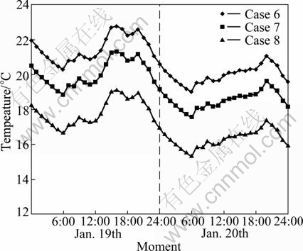
Fig. 14 Hourly temperature changes of cases 6-8
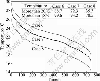
Fig. 15 Accumulation curves of hourly temperature of cases 6-8
Based on above analysis, with the smaller heat (800 W) input into crawlspace, excellent first floor thermal environment can be made by using the crawlspace warm air heating system.
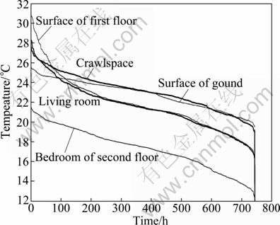
Fig. 16 Hourly temperature accumulation curve (Case 7)
5.4 Heat amount for different month in heating period
Using the same floor air diffusers, wind velocity and foundation insulation condition as Case 7, and under the condition that the heat amount is 600 W input into crawlspace in December, 800 W in February and January and 600 W in March, the average temperature of different point is concluded in Table 7. It can be found that the living room temperature is higher than 21 °C. The first floor surface temperature is about 22 °C. For the bedroom on the second floor, the temperature is also about 18 °C.
6 Conclusions
1) According to the measurement, the crawlspace heating system is effective in the practical application for the detached house in the moderate and humid climate region of Japan. It can make the living room average temperature above 20 °C.
2) The existing of the floor air diffusers and the increase of the wind amount circulating between crawlspace and indoor space can improve the indoor thermal environment for the warm air crawlspace heating system.
3) The design for the crawlspace considering both the adoption of thermal storage part and the utilization of the stable thermal condition of ground is useful for the crawlspace heating system to make comfortable indoor thermal environment.
Table 7 Monthly average temperature of different points
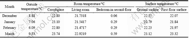
4) For the simulated detached house, in order to gain the comfortable indoor thermal environment, the heat amount input to the crawlspace is 600 W in December, 800 W in February and January and 600 W in March respectively.
References
[1] HONMA Y, SUZUKI H, SAKAMOTO Y, NAGATA A, IWAMAE A. The characteristics of hygrothermal behavior in the crawlspace in winter. Study on vertical edge insulation method for the moderate and humid climate region: Part 1 [J]. Journal of Planning Engineering, AIJ, 1999, 525: 33-38.
[2] HONMA Y, SUZUKI H, SAKAMOTO Y. The hygrothermal environment in the crawlspace insulated on foundation wall in the summer involving rainy season. Study on vertical edge insulation method for the moderate and humid climate region: Part 2 [J]. Journal of Planning Engineering, AIJ, 2000, 530: 25-30.
[3] FUKUSHIMA A, ENAI M, MIYAURA M, HONMA Y. Application of passive ventilation system with crawlspace heating to the practical house, passive ventilation strategy and systems in cold region: Part 2 [J]. Journal of Planning Engineering, AIJ, 2000, 532: 51-56.
[4] KYU N R, MYOUNG S Y, KIM K W. Evaluation of the control performance of hydronic radiant heating systems based on the emulation using hardware-in-the-loop simulation [J]. Building and Environment, 2011, 46(10): 2012-2022.
[5] JIN Xing, ZHANG Xiao-song, LUO Ya-jun, CAO Rong-quan. Numerical simulation of radiant floor cooling system: The effects of thermal resistance of pipe and water velocity on the performance [J]. Building and Environment, 2010, 45(11): 2545-2552.
[6] LAOUADI A. Development of a radiant heating and cooling model for building energy simulation software [J]. Building and Environment, 2004, 39(4): 421-431.
[7] KILKIS ? B, SAGER S S, ULUDAG M. A simplified model for radiant heating and cooling panels [J]. Simulation Practice and Theory, 1994, 2(2): 61-76.
[8] AHN Byung-Cheon, SONG Jae-Yeob. Control characteristics and heating performance analysis of automatic thermostatic valves for radiant slab heating system in residential apartments [J]. Energy, 2010, 35(4): 1615-1624.
[9] CHO S H, ZAHEER-UDDIN M. Predictive control of intermittently operated radiant floor heating systems [J]. Energy Conversion and Management, 2003, 44(8): 1333-1342.
[10] RAHIMI M, SABERNAEEMI A. Experimental study of radiation and free convection in an enclosure with a radiant ceiling heating system [J]. Energy and Buildings, 2010, 12(11): 2077-2082.
[11] MAXIME T G, LOUIS G. Investigation on heat transfer modeling assumptions for radiant panels with serpentine layout [J]. Energy and Buildings, 2011, 43(7): 1598-1608.
[12] CAUSONE F, CORGNATI S P, FILIPPI M, OLESEN B W. Experimental evaluation of heat transfer coefficients between radiant ceiling and room [J]. Energy and Buildings, 2009, 41(6): 622-628.
[13] TIAN Z, LOVE J A. A field study of occupant thermal comfort and thermal environments with radiant slab cooling [J]. Building and Environment, 2008, 43(10): 1658-1670.
[14] CHIANG Wei-Hwa, WANG Chia-Ying, HUANG Jian-Sheng. Evaluation of cooling ceiling and mechanical ventilation systems on thermal comfort using CFD study in an office for subtropical region [J]. Building and Environment, 2012, 49: 113-127.
[15] CATALINA T, VIRGONE J, KUZNIK F. Evaluation of thermal comfort using combined CFD and experimentation study in a test room equipped with a cooling ceiling [J]. Building and Environment, 2009, 44(8): 1740-1750.
[16] HE Jiang. A design supporting simulation system for predicting and evaluating the cool microclimate creating effect of passive evaporative cooling walls [J]. Building and Environment, 2011, 46(3): 584-596.
[17] MAGNIER L, ZMEUREANU R, DEROME D. Experimental assessment of the velocity and temperature distribution in an indoor displacement ventilation jet [J]. Building and Environment, 2012, 47: 150-160.
(Edited by YANG Bing)
Foundation item: Project(10YZ156) supported by Innovation Program of Shanghai Municipal Education Commission, China; Project(sdl09009) supported by Training Program for Outstanding Youth Teacher of Shanghai Municipal Education Commission, China; Project(Z2010-103) supported by Shanghai Education Development Foundation, China
Received date: 2011-07-26; Accepted date: 2011-11-14
Corresponding author: RUAN Ying-jun, Associate Professor; PhD; Tel: +86-21-65980685; E-mail: snail2418@sina.com

