J. Cent. South Univ. (2013) 20: 354�C362
DOI: 10.1007/s11771-013-1495-x

Loaded multi-tooth contact analysis and calculation for contact stress of face-gear drive with spur involute pinion
TANG Jin-yuan(�ƽ�Ԫ), LIU Yan-ping(����ƽ)
State Key Laboratory of High-performance Complex Manufacturing,
School of Mechanical and Electrical Engineering, Central South University, Changsha 410083, China
 Central South University Press and Springer-Verlag Berlin Heidelberg 2013
Abstract: The analytical method based on ��Hertz theory on normal contact of elastic solids�� and the numerical method based on finite element method (FEM) calculating the contact stress of face-gear drive with spur involute pinion were introduced, and their relative errors are below 10%, except edge contact, which turns out that these two methods can compute contact stress of face-gear drive correctly and effectively. An agreement of the localized bearing contact stress is gotten for these two methods, making sure that the calculation results of FEM are reliable. The loaded meshing simulations of multi-tooth FEM model were developed, and the determination of the transmission error and the maximal load distribution factor of face-gear drive under torques were given. A formula for the maximal load distribution factor was proposed. By introducing the maximal load distribution factor in multi-tooth contact zone, a method for calculating the maximal contact stress in multi-tooth contact can be given. Compared to FEM, the results of these formulae are proved to be reliable, and the relative errors are below 10%.
Key words: face gear; contact stress; finite element method; loaded meshing simulation; load distribution factor; multi-tooth contact
1 Introduction
Face-gear drive has been applied in helicopter transmissions as a result of the advantages, such as split of the torque, reduction of weight, decrease of mechanism space and absence of axial force, which is suitable for high-speed and heavy-load transmissions in comparison with others [1�C2], and plays a very important role in aeronautical field for longer working life and higher security. In order to know the maximal load torque and working life of face gear, it is necessary to study the bending strength and contact strength [3�C4]. In terms of the contact stress of face gear drive, it is easy to seek methods to solute it for a single tooth model, while with multi-tooth in contact, this question becomes very difficult.
Litvin and EGELL [5] had defined the theoretical study of face gear analytically, such as theories of engagement, tooth contact analysis and so on. In NASA��s reports, contact and bending stresses were investigated in different versions of geometry of face- gear drive, using a finite element method (FEM) model with five teeth [6]. Barone et al [7] also implemented a finite element meshing simulation with the three teeth FEM model. The program ��FACET�� in Europe had developed a ��GANDALF�� software [8], which provided an analytical method for stress calculation of face gears and carried out an experimental validation, but without a detailed computational process and results of contact stress.
Two methods to compute the contact stress of face-gear drive in single tooth contact are studied in this work comparatively. The first one is an analytical method based on ��Hertz theory on normal contact of elastic solids��[9], which is applicable to face-gear drive with localized bearing contact; the other is a numerical method based on FEM for contact of single tooth [10�C12]. Although, they are developed and known well, the results of these methods upon the face-gear drive are compared, and an agreement between them is obtained. The analytical method makes the results of FEM more reliable, then the mesh amount of the single tooth in finite element model can be determined to get an exact value of contact stress, which is not mentioned in other works. So, we insist a reference on the mesh size of the FEM model according to the contact stress, which can be given with the analytical method, and the results of the finite element analysis for the loaded meshing simulation would become more reliable.
With ABAQUS software, a FEM model with five or seven teeth is built, which is different from the FEM mentioned in Refs. [5�C6]. Contact stresses can be calculated during meshing simulation in the five teeth FEM model, while the transmission error and maximal load distribution factor can be obtained through the seven teeth one. Based on this method, a formula is constructed for the maximal load distribution factor, which concerns about the maximal contact stress for the contact of multi-tooth. Through this formula and method, the maximal contact stress in multi-tooth contact would be affirmed.
2 Research on contact stresses of single tooth model for face-gear drive
Here, two methods to calculate the contact stresses of single tooth are proposed comparatively. The two methods are ��Hertz theory on normal contact of elastic solids�� and FEM in ABAQUS.
2.1 Tooth contact analysis of face gear drive based on an analytical method
The appearances of tooth flank are different between face gears and spur involute pinions, and they are smooth and non-conforming surfaces in contact. When the friction between the tooth flanks is out of consideration, only normal contact force exists; when considering the point contact, the elliptic contact zone is only a fraction of tooth flank (without regarding to edge contact), and their principal relative radii of curvature are rather small. Therefore, the theories of contact mechanics is applicable to studying the contact stresses and deformations of face gear loaded.
2.1.1 Hertz theory on normal contact of elastic solids for general profiles
A normal force P is applied between the profile 1 and profile 2 (see Fig. 1). Before deformation, the separation between the corresponding points S1 and S2 is h. During the compression, distant points M1 and M2 move towards point O, parallel to z axis, by displacements ��1 and ��2. The profiles would overlap with the assumption of non-deformation, just like the dotted lines in Fig. 1. Due to the pressure, the profiles are displaced by amounts u1 and u2 relative to the distant points M1 and M2. The corresponding points S1 and S2 should satisfy the displacement compatibility conditions, which is determined as follows:
Inside the contact zone:
 (1)
(1)
Or, outside the contact zone:
 (2)
(2)
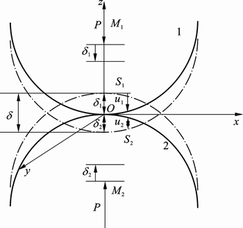
Fig. 1 Point contact of general profiles
The equations of profiles can be outspreaded by Maclaurin Series. When the radii of curvature of the profiles are large enough, higher order terms are neglected:

 (3)
(3)
When a proper coordinate system is adopted, C1 and C2 come to zero, and A1, B1, A2 and B2 are relative to the principal radii of curvature. We can express z1 and z2 in the same coordinate system, and h is written as the equation below:
 (4)
(4)
where A and B are defined by
 (5)
(5)
where ��11 and ��12 are the principal curvatures of surface 1, while ��21, ��22 are the ones of surface 2. �� represents the included angle between the first principal directions of these two surfaces. In terms of their principal curvatures, convex surface and concave surface are ascribed to positive sign and negative sign, respectively. It is generally recognized that B is not less than A.
Through stress analysis in the contact zone, it is known that
 (6)
(6)
where parameters L, M and N are relative to elliptic integrals. Substituting Eqs.(4) and (6) into Eq. (1), we get
 (7)
(7)
then
 (8)
(8)
where e is the eccentricity of ellipse; K(e) and E(e) are the first and the second elliptic integrals, respectively; a is the semi-major axis, and b is the semi-minor axis; p0 is the maximal contact stress. It is assumed that the normal contact force of the surfaces is P; Poisson ratios of materials are ��1 and ��2, respectively; The elastic moduli are E1 and E2, respectively. So, the parameters e, p0, a and b in Eq. (8) can be defined as
 (9)
(9)
In order to obtain the value of e, we can use the numerical method to solve the first formula of Eq. (9). The results of solution are
 (10)
(10)
2.1.2 Contact force of face gear drive under torque
Usually, the torque of transmission upon pinion is known. But the values of normal contact force should be calculated, when computing the contact stress of tooth flank. The face gear meshes with pinion at point M, and the torque on the pinion is T (N��m) (see Fig. 2). It is easily known that, the action line of force P is tangent with base circle Rb1 (m), so force P can be obtained as
P=T/Rb1 (11)
(11)
2.1.3 Calculation of contact path and principal curvatures of meshing points
Considering that tooth number of pinion is less than the ones of shaper, the contact point of face-gear drive is presented, in which the contact path shifts as a result of assembly error [13]. Before carrying out LTCA based on ��Hertz theory on normal contact of elastic solids��, it is necessary to obtain the contact points and their principal curvatures. Discarding assembly error, a numerical example is taken into account, as listed in Table 1.
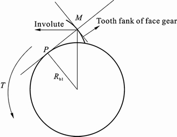
Fig. 2 Contact force at a meshing point
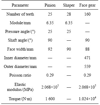
Table 1 Parameters of face gear drive
The meshing equation of face gear drive is:

 (12)
(12)
This equation includes six unknowns and five independent formulae, and it can be solved by a numerical method. Figure 3 shows the contact path, which includes eleven meshing points. In terms of their principal curvatures of face-gear, if the first one is positive, and the second one is negative, then its two principal centers of curvature stand different sides to normal. So, it is regarded as convex surface in the first principal direction and concave surface in the second one. For pinion, the tooth flank is convex surface. Coming to the values of A and B in Eq. (5), ��11 and ��12 are positive and negative, respectively, while ��21 and ��22 are both positive. The results are given in Table 2.
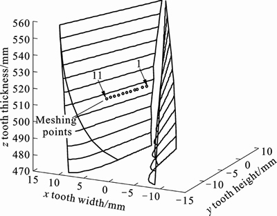
Fig. 3 Contact path without installation errors
2.1.4 Calculation procedures of maximal Hertz contact stresses.
1) Follow the rules on the sign of principal curvatures, and take ��11, ��12, ��21 and ��22 in Table 2 into Eq. (5), then the values of A and B are obtained.
2) Use the numerical method to solve the value of e in the first formula of Eq. (9).
3) When the torque T (1 600 N��m) is determined, through Eq. (11), the values of normal contact force P on every meshing point can be gotten.
4) Bring the values of e and P into Eq. (10) and solve the values of a and b. The maximal contact stress is obtained in the third formula of Eq. (10).
Following the procedures above, the results can be obtained, as listed in Table 3.
Table 3 shows that, the semi-major axis at meshing point 1 reaches 49.14 mm, while the face width is 88 mm, so the contact zone exceeds the gear surface. In this situation, it mismatches the conditions of elastic half-space theory, and the value of contact stress is smaller. The edge contact exists, and there is a stress concentration.
2.2 Contact stress by FEM based on ABAQUS
In order to validate the results of analytical method above, and determine the mesh amounts of FEM model for an exact value of contact stress, a single tooth FEM model was created under the same torque, namely T=1600 N��m. In the meshing coordinate system without assembly errors, the models of face gear and pinion are built. Finite element analyses were introduced in detail in Ref. [6], so we can give the same boundary condition as Ref. [6]. But the values of contact stresses could not be determined exactly, before a proper mesh size is given. With the contrast between the results of these two methods, different mesh amounts are continuously attempted, and the balance achieves. At last, the proper mesh size is found, and the results become more reliable.
As shown in Fig. 4, after installation, the face gear and pinion both take the right meshing position. In Table 2 and Fig. 3, there are eleven positions to calculate. The first meshing point is point 6; as for other points, we need to rotate the right rotation angle at Table 2 around their axes.
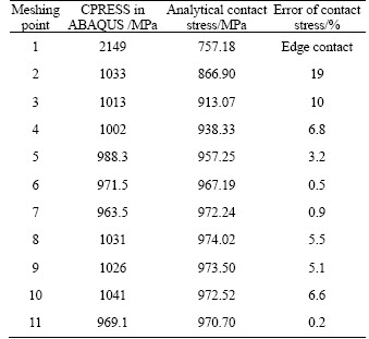
In the step module of ABAQUS, with the contact stress of history output and field output, and we can get the relative results. The output of CPRESS is the contact stress that we need, because there is no friction in the model [14]. Figures 5�C6 are the cloud pictures of meshing point 6 and meshing point 1, respectively, and it states that the edge contact happens at meshing point 1. The results of two methods are described, and compared in detail as listed in table 4.
2.3 Interpretation and comparison of results
For the meshing points close to the addendum, their semi-major axes are longer, while their contact stresses are less. The meshing points 1 and 2 are close to the addendum, so the results are slightly unreliable. As shown in Fig. 6 and Table 4, the edge contact appears at meshing point 1. Due to the existence of edge contact,the analytical method fails, and the error in contrast is vast. The stress concentration happens in ABAQUS at point 1. At every meshing point except points 1 and 2, the errors of contact stresses are all below 10%, and the contact forces of two methods have identical value. It is proved that the two methods of contact stress calculation are verified by each other.
Table 2 Numerical values of contact points by TCA
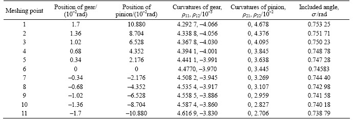
Table 3 Results calculated by LTCA based on Hertz theory
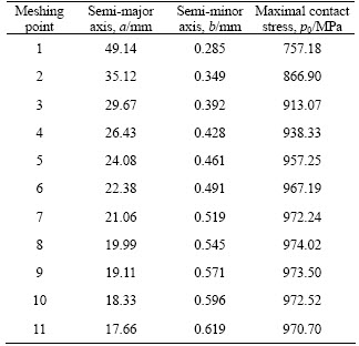
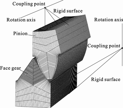
Fig. 4 Model of single tooth contact
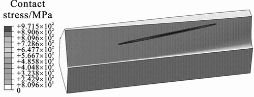
Fig. 5 Contact stress of meshing point 6
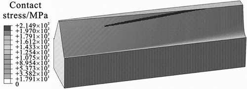
Fig. 6 Contact stress of meshing point 1
Table 4 Comparison between these two methods
3 Loaded meshing simulation of multi-tooth model based on ABAQUS
3.1 multi -tooth FEM models created
Taking the face-gear parameters into account as shown in Table 1, we can build the FEM models with multi-tooth in ABAQUS [15], which is used to the loaded meshing simulation. The contact stresses are calculated in the FEM models with five teeth, and the middle tooth have refined mesh, whose size should come up to one of single tooth FEM model mentioned above. To research the transmission error and maximal load distribution factor, the model with seven teeth is necessary, because the contact ratio of face gear is greater than two. The finite element analysis models are shown in Figs.7�C8. The FEM on face-gear are proposed in Refs. [6�C7], in which all degrees of freedom of the gear are fixed, and the torque on the pinion about its rotation axis is applied. We would like to take this method as the loaded analysis, not a loaded meshing simulation. To achieve this, we give an angular displacement on the coupling point of pinion, which is about the rotation axis, so the gear can rotate with the pinion by the contact ratio; the torque is applied on the coupling point of gear, and the degree of freedom about its rotation axis should be released, as shown in Fig. 7.
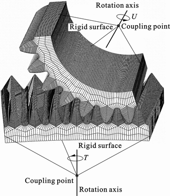
Fig. 7 Model with seven teeth
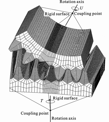
Fig. 8 Model with five teeth
3.2 Loaded meshing simulation of FEM model with seven teeth
When the contact ratio is larger than two, it means that there are three teeth in contact at the same time. In this situation, a seven teeth model is required, because five teeth are not enough to research transmission errors and load distribution factor.
3.2.1 Outputs for transmission errors of face-gear drive
During the loaded meshing simulation, the loaded transmission error is computed at every rotation position. The angular displacements of the pinion and gear are recorded at any moment of simulation. Then, the loaded transmission error is defined by
 (13)
(13)
where ����1 and ����2 are the angular displacements of the pinion and gear, respectively, z1 and z2 represent the tooth number, and ���� is the loaded transmission error.
In the history outputs of ABAQUS, the angular displacements of the coupling points of gear and pinion are recorded at every moment. Through Eq. (13), the loaded transmission error is obtained (see Fig. 9). The conclusion shows that, under different torques, the transmission errors are presented in different levels. The amplitude increases with the loaded torque, while the transmission is steadier.
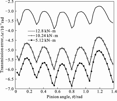
Fig. 9 Transmission errors of face-gear drive
3.2.2 Outputs for load distribution factor of face-gear drive
If the contact ratio is larger than two, there are two or three pairs of teeth in meshing. Under a torque, the total contact force is constant, which is decided by Eq. (11). The ABAQUS can export contact force of every contact pair, recorded in the history of outputs as CNORMF (see Fig. 10). Assuming that the contact force of contact pair 2 is P2, while P1 and P3 represent the contact forces of contact pair 1 and 3, respectively, we can obtain the load distribution factor of the contact pair 2 by
 (14)
(14)
At last, computed with Eq. (14), the load distribution factor of the contact pair 2 is shown in Fig. 11, and its maximum value is gotten in the posted process of ABAQUS. Obviously, the contact force of a contact pair is also decided by
 (15)
(15)
3.3 Loaded meshing simulation of FEM model with five teeth
To reduce the consuming time of ABAQUS, a FEM model was created with five teeth (see Fig.8), to compute the contact stresses of teeth in contact, the amount of mesh should be confirmed to be large enough to calculate the contact stress exactly. In the field outputs of ABAQUS, we can know the contact stresses from the outputs of CPRESS. Figure 12 shows the cloud picture of the contact stress in a moment (the loaded torque on gear is 10.24 kN��m, the same below). When the teeth come into or quit meshing, the edge contact happens, as shown in Fig. 13 and Fig. 14. In Fig. 15, the curve of contact stresses in the whole meshing process is given, and the maximal contact stress is 894.3 MPa (see Fig. 12), excluding edge contact, which happens in the boundary of double-tooth meshing region.
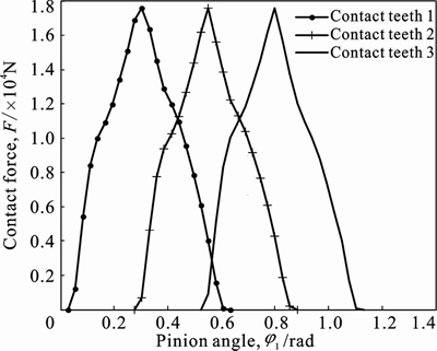
Fig. 10 Contact force of contact teeth
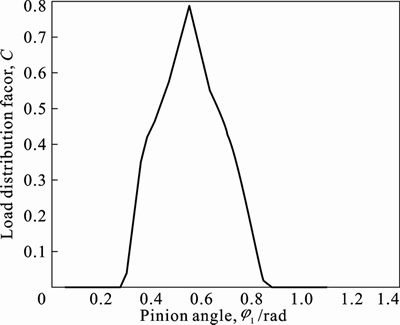
Fig. 11 Load distribution factor
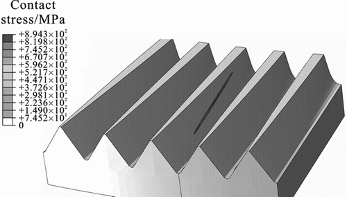
Fig. 12 Cloud picture of maximal contact stress
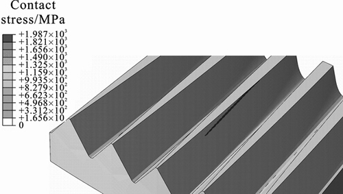
Fig. 13 Edge contact caused by gear
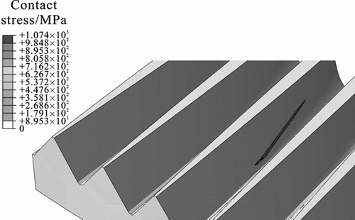
Fig. 14 Edge contact caused by pinion
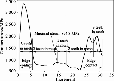
Fig. 15 Curve of contact stresses
4 An analytical computational method for maximal contact stress of multi-tooth contact model
Basing on the results in Table 3, we think the contact stress of every meshing point is approximate, because their induced curvatures are almost identical. As we know, with the tooth deformation caused by contact, the shifts of contact path along the direction of tooth width can be ignored. So, the pitch point of the face-gear can be used to compute the maximal contact stress approximately during meshing. Then, the Eq. (15) is used to get the maximal contact force P of one tooth in meshing. Most of all, the maximal load distribution factor Cp should be known.
4.1 Determination for maximal load distribution factor Cp
In the previous part of this work, we have exhibited calculation of the maximal load distribution factor. With this method, Cp is determined by three variables: the number teeth of face gear z2, the gear ratio i, and the torque upon unit module T/m (the torque T divide module m). It may be expressed by
Cpm=f(i, z2, T/m) (16)
To get the expression of Eq. (16), we created a panel with lots of face-gear drive models, where gear ratio i is varying from 1 to 7, and the number teeth of face gear z2 is from 40 to 200. Under several different torques (T/m), we calculate the maximal load distribution factors of FEM model mentioned above. With these data from the sample, the expression can be made by nonlinear regression as below:

 (17)
(17)
In Eq. (17), the variables x1, x2 and x3 represent the gear ratio i, the number teeth of face gear z2, and the torque upon unit module T/m, respectively.
4.2 Analytical method for maximal contact stress of face-gear drive
According to the research above, the calculation of the maximal contact stress for face-gear drive could be carried out by the following steps:
1) Determine the parameters face gear model (z2, i and m) and loaded torques (T);
2) Calculate the maximal load distribution factor Cpm by Eq. (17), then the maximal contact force Pmax of a meshing tooth would be deduced.
3) Define the pitch point of the face-gear, and operate the Eq. (10) on it.
4) After step 3, take the value of Pmax into Eq. (10), then the maximal contact stress can be computed.
4.3 Case verification
According to Table 1, the parameter i, z2 and T/m are 6.4, 160 and 252 kN, respectively. In Eq. (17), the Cpm is given as 0.73, then embedding the value of Pmax into Eq. (10). At last, the maximal contact stress is computed and the value is 890.6 MPa. This value is identical to the result deduced in FEM model with five teeth (894.3 MPa).
5 Conclusions
1) Based on a single tooth model, two methods for the determination of contact stress of face-gear drive is introduced and compared in this work. The analytical method can give a validation for the FEM, and the values of contact stresses are more accurate by the determination of the amount of mesh in FEM model.
2) The FEM models with multi-tooth contact are established. Through the loaded meshing simulation, the transmission errors and the load distribution factor are computed. Results show that the amplitudes of transmission error increase with loaded torques.
3) With five teeth FEM models, the place of maximal contact stress is determined except edge contact. The reference on the reasonable mesh amount is given, and the values of contact stresses are more accurate.
4) The formula of the maximal load distribution factor is given out, and a new method is introduced to calculate the value of the maximal contact stress approximately. It turns out that this method is as reliable as the FEM.
References
[1] HEATH, G F, BOSSLER, R B. Advanced rotorcraft transmission (ART) program-final report [R]. Washington, DC: McDonnell Douglas Helicopter Company, 1993.
[2] LEWICKI D G, HEATH G F. Face gear surface durability investigations [J]. Journal of the American Helicopter Society, 2008, 53(3): 282�C289.
[3] LITVIN F L, IGNACIO G P, Kenji Y. Design, simulation of meshing, and contact stresses for an improved worm gear drive [J]. Mechanism and Machine Theory, 2007, 42: 940�C959.
[4] ZHAO Ning, GUO Hui, FANG Zong-de. Loaded tooth contact analysis of modified helical face gears [C]// Advanced Design and Manufacture to Gain a Competitive Edge. New York: Springer, 2008: 345�C354.
[5] LITVIN F L, EGELI A. Handbook on face gear drives with a spur involute pinion [R]. Chicago: The Boeing company, 2000.
[6] LITVIN F L, FUENTES A. Face-gear drive with spur involute pinion: Geometry, generation by a worm, stress analysis [J]. Computer Methods in Applied Mechanics and Engineering, 2002, 191: 2785�C2813.
[7] BARONE S, BORGIANNI L, FORTE P. Evaluation of the effect of misalignment and profile modification in face gear drive by a finite element meshing simulation [J]. Journal of Mechanical Design, 2004, 126(5): 916-924.
[8] GUINGAND M, VAUJANY J P, JACQUIN C Y. Quasi-static analysis of a face gear under torque [J]. Computer Methods in Applied Mechanics and Engineering, 2005, 194: 4301�C4318.
[9] JOHNSON K L. Contact mechanics [M]. London: Cambridge University Press, 1985: 179�C236.
[10] LIN T J, OU H. A finite element method for 3D static and dynamic contact/impact analysis of gear drives [J]. Computer Methods in Applied Mechanics and Engineering, 2007, 196: 1716�C1728.
[11] NAPAU M, NAPAU I D. Computerized modeling and simulation of idle and loaded multi-tooth contact analysis in worm-face gear drives [J]. Computers and Information in Engineering, 2007, 4: 1�C10.
[12] WU S H, TSAI S J. Contact stress analysis of skew conical involute gear drives in approximate line contact [J]. Mechanism and Machine Theory, 2009, 44: 1658�C1676
[13] LITVIN F L. Gear geometry and applied theory [M]. Shanghai: Shanghai Science and Technology Press, 2008: 258�C282.
[14] LI S. Finite element analyses for contact strength and bending strength of a pair of spur gears with machining errors, assembly errors and tooth modifications [J]. Mechanism and Machine Theory, 2007, 42: 88�C114.
[15] SHI Yi-ping. FAQ and solution of ABAQUS [M]. Beijing: China Machine Press, 2009: 156�C181. (in Chinese)
(Edited by HE Yun-bin)
Foundation item: Project(50875263) supported by the National Natural Science Foundation of China; Project(2011CB706800) supported by the National Basic Research Program of China;Project(2010ssxt172) supported by the Natural Science Foundation of Hunan Province, China
Received date: 2012-02-28; Accepted date: 2012-05-24
Corresponding author: TANG Jin-yuan, Professor; Tel: +86�C731�C88877746;Email: jytangcsu@yahoo.com.cn

