J. Cent. South Univ. (2012) 19: 2173-2178
DOI: 10.1007/s11771-012-1261-5
Stress distribution and fatigue life of built-up sleeved backup roll
ZHU Zhong-ying(����Ӣ), SUN Deng-yue(�����), XU Shi-ming(��ʯ��)
National Engineering Technology Research Center of Cold Rolling Strip Equipment and Technology,
Yanshan University, Qinhuangdao 066004, China
? Central South University Press and Springer-Verlag Berlin Heidelberg 2012
Abstract: The advantage of built-up sleeved backup roll was described. Based on the stress distribution analysis and simulation for the built-up sleeved backup roll by using finite element method, the effects of roll sleeve thickness and shrink range on the stress-strain field were studied. Finally, based on the methodology and strategy of the fatigue analysis, fatigue life of backup roll was estimated by using the stress-strain data obtained through finite element simulation. The results show that roll sleeve thickness and shrink range have a great influence on sleeve stress distribution of built-up sleeved roll. Under the circumstance of ensuring transferring enough torque, the shrink range should be kept small. However, thicker roll sleeve has longer roll service life when the shrink range is constant.
Key words: built-up sleeved backup roll; stress-strain analysis; finite element method; shrink range; fatigue life
1 Introduction
Large rolling mill is the key technology equipment of modern metallurgic plant, and the backup roll is the core component of mill. With the development of modern hot strip mill to large-scale, high-speed and automated direction, the demand for hot roll backup becomes higher and higher. It requires the resistance to bend, and to have good wear-resisting property. However, meeting these two requirements simultaneously is very difficult or costly. Built-up sleeved backup roll solves the problem of roll wear and fracture resistance [1].
The built-up sleeved backup roll [2] is a branch of the forged steel backup roll family. It consists of roll core and roll sleeve. The roll core is made by high ductile steel material while roll sleeve is made by high hardness and high wear resistant steel material. Then, these two parts are assembled together by shrink fit, composing a new kind of roll. This kind of roll, with good mechanical properties [3], is difficult to break and wear because it has great ductility inside and high hardness and wear resistance outside. In addition, roll core can be used repetitively. Thereby, the application and development of built-up backup roll present several advantages in preventing roll-break, increasing operating rate and reducing roll consumption and the cost of rolling.
Currently, roll sleeved technology has been mostly used in the area of the repairing work of failed backup rolls. QIAO et al [4] described the manufacturing process of the compound bushing rolls in the aspect of melting, pouring, forging, heat treatment and machining. JI [5] introduced the repairing of chilled iron roller with section inlay sleeves, analyzed the abradability of high-chromium iron and production process of wear-resistant sleeve and provided a roller repairing plan which improves the wear-resistance, service life and high maintenance cost. But the application and promotion for newly-made built-up sleeved rolls are unsatisfactory, which are mainly attributed to the insufficient understanding on the research of roll stress and fatigue life. It is widely known that stress state highly affects the fatigue performance of roll [6]. RAD [7] investigated premature failure of back-up roll in experimental procedure. ARIF et al [8] and BENASCIUTTIA et al [9] determined roll deformation and stress distribution in rolling process. For sleeved rolls only are used in roll casting [10] and section rolling [11], the stresses and strains in large sleeved backup roll are known to the authors. In the present work, the stress field and fatigue life of built-up sleeved backup roll will be studied from two aspects: roll sleeve thickness and shrink range.
2 Built-up backup roll finite element analysis
2.1 Shrink range selection
A shrink fit is a semi-permanent assembly system that can resist the relative movement or transmit torque between two components through the creation of high radial pressures at the interface of its constituent parts. In order to ensure the reliability of fitting, the key is to determine the optimum interference between roll sleeve and roll core [12-14]. The link will fail or generate sliding under the load if the shrink fit is improper. So, shrink fit must be properly designed and produced in order to achieve the required functionality in a consistent manner.
Conventional design method is mainly based on analogy pattern, and the shrink range of sleeved roll is generally selected in the range of 0.03%-0.10%, but in different conditions, varies considerably.
2.2 Simplified model of backup roll and work roll
For roll with axial length much larger than contact area, we can simplify two-dimensional plane strain model, which not only greatly reduces the demands on the computer configuration but also the computing time. And the results are also reasonable [15]. The model is created in ABAQUS CAE.
The simplified model of roll is shown in Fig. 1.
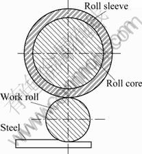
Fig. 1 Simplified model of roll
2.3 Finite element model
For four-roll mill, generally work roll works as driving roll and backup roll works as driven roll. The work roll drives backup roll by the friction force at the interface of them. The stress-strain field of backup roll is mainly studied, so we only need to establish the model of backup roll and work roll.
2.3.1 Setting interaction
In this model, two groups of interaction should be defined between roll sleeve and roll core, and between roll sleeve and work roll, respectively. The coefficient of friction between roll sleeve and roll core is 0.3, and the normal direction is ��hard�� contact. The coefficient of friction between roll sleeve and work roll is 0.1, and the normal direction is also ��hard�� contact.
2.3.2 Boundary conditions
An entity unit in finite element has no rotation degrees of freedom, so we could set a reference point (RP, as shown in Fig. 2) in the center of roll coupling regional nodes to define the rotation [16]. In order to accurately take account of the true roll operating conditions, some measures should be taken. The boundary conditions used in the finite element analysis are as follows: 1) Set restraints on the reference points of the roll sleeve and roll core including the translation (U1, U2) and rotation (VR3) degrees of freedom; 2) Add the roll pressure in the U2 direction to the reference point of the roll core and release this direction freedom at the same time; 3) Add angular velocity for work roll while relaxing the rotation degrees of freedom of backup roll and work roll, so that the work roll can drive backup roll by the contact pressure and friction force between them.
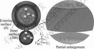
Fig. 2 Meshing results of roll model
2.3.3 Meshing and calculation
In order to accurately simulate the stress state of the roll, mesh must be refined towards roll sleeve, outer periphery of work roll and roll core. Roll sleeve, outer periphery of work roll and roll core are meshed with quad element shape, sweep grid, and the other part with quad-dominated shape, sweep grid. The element type was all set as CPE4I (4-node bilinear plane strain quadrilateral, incompatible mode) [17]. The meshing result of roll model is shown in Fig. 2.
2.4 Results comparison
2.4.1 Results analyzing for rolls with different sleeve thicknesses
The parameters of model with different thicknesses are listed in Table 1.
Figure 3 shows the equivalent stress distribution of points along the radial direction of the roll sleeve. It is shown that the stresses along the roll sleeve radial direction exhibit a linear relationship when the roll only bears assembly stress. It can be found that as the roll sleeve thickness increases, the surface stresses of rolls decrease, the stresses at the inner surface vary little remaining ~500 MPa for rolls with different sleeve thicknesses when the shrink range is 2 mm. The equivalent stress curves of three kinds of rolls maintain a parallel state.
Table 1 Parameters of model with different sleeve thicknesses
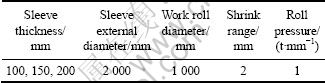
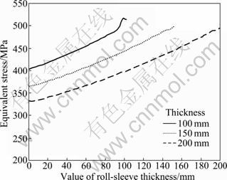
Fig. 3 Equivalent stress distribution of points along radial direction of roll sleeve
Figure 4 shows equivalent stress distribution of one point of the roll sleeve surface with different sleeve thicknesses. It can be known from the curves that the surface stresses remain the value of initial fit stress in the non-rolling area, while once that point rolls into the contact area, the stress value quickly reaches ~750 MPa. The sleeve thicknesses are different, but the maximum stresses vary little.
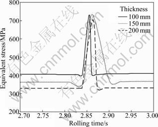
Fig. 4 Equivalent stress distribution of one point of roll sleeve surface
Figure 5 shows equivalent stress distribution of points along the radial direction of the roll sleeve in the contact area. The maximum stress value of 1 050 MPa occurs in the depth of 3-6 mm away from the roll sleeve surface. Then, the stress value reduces rapidly along the radial direction. When the depth is above 60 mm, the curve becomes flatter, slowly rising in radial direction.
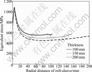
Fig. 5 Equivalent stress distribution of points along radial direction of roll sleeve
Figure 6 shows the logarithmic strain distribution of points along the radial direction of the roll sleeve in the contact area. The strain curves keep the same trend with the stress curves in Fig. 6. This is also consistent with the corresponding relationship between stress and strain.
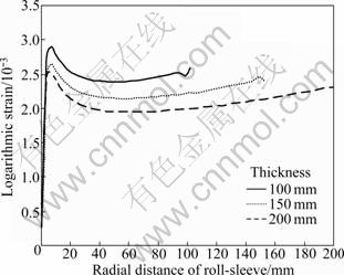
Fig. 6 Logarithmic strain distribution of points along radial direction of roll sleeve
Figure 7 shows the logarithmic strain distribution of points at the interface of the roll sleeve and roll core. With the same shrink range and the same roll pressure, logarithmic strains at the roll sleeve inner surface produce great difference. The greater the sleeve thickness is, the lower the logarithmic strain value is, which will be beneficial to the roll life. Therefore, the thicker the sleeve under the strength, the better the processing.
2.4.2 Results analyzing for rolls with different shrink ranges
The parameters of model with different shrink ranges are listed in Table 2. Figure 8 shows equivalent stress distribution of points along the radial direction of the roll sleeve of 200 mm thickness. Figure 8 shows that the stresses resulting from the internal pressures exhibit a linear relationship when the roll only bears shrink fit force. When the shrink range is 1.0 mm, the surface stress is 160 MPa and the inner surface stress reaches a maximum value of 250 MPa. Thus, the shrink range is 1.5 mm, the surface stress is 250 MPa with the inner surface stress reaching 375 MPa. For the high shrink range of 2.0 mm, the surface stress is 330 MPa and the inner surface stress approaches 500 MPa. It is not difficult for us to find that the equivalent stresses are directly proportional to the shrink ranges under the same sleeve thickness.
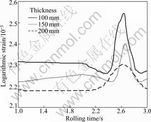
Fig. 7 Logarithmic strain distribution of points at interface between roll sleeve and roll core
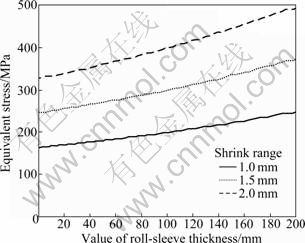
Fig. 8 Equivalent stress distribution of points along radial direction of roll sleeve
Table 2 Parameters of model with different shrink ranges
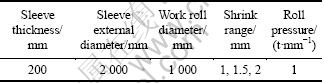
Figure 9 shows the equivalent stress distribution of one point of the roll sleeve surface in different shrink range. It can be informed from the curve that the surface stresses remain the value of initial fit stress in the non-rolling area, while once that point rolls into the contact area, the value of stress quickly reaches peak point. The greater the shrink range is, the greater the stress would be. Like the shrink range of 1.0 mm, the stress rapidly reached ~400 MPa. Nevertheless, for the shrink range of 2.0 mm, the maximum stress value is up to ~800 MPa. Therefore, ensuring transferring enough torque, the shrink range should be chosen as smaller as possible. This can ensure that the roll surface stress values ??remain low in rolling process.
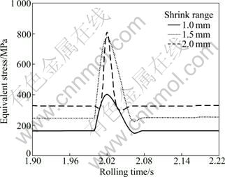
Fig. 9 Equivalent stress distribution of one point of roll sleeve surface
Figure 10 shows equivalent stress distribution of points along the radial direction of the roll sleeve in the contact area. Figure 10 shows that the maximum stress value is located in the depth of 3-6 mm away from the roll sleeve surface. For different shrink ranges of 1.0, 1.5 and 2.0 mm, the peak stresses in turn are 850, 860 and 1 050 MPa, respectively. Then, the stress reduces rapidly along the radial direction. When the depth is above 60 mm, the curve is becomes flatter, slowly rising in radial direction. This again shows that the shrink range cannot be selected too large, otherwise the stress will vary severely in rolling process.
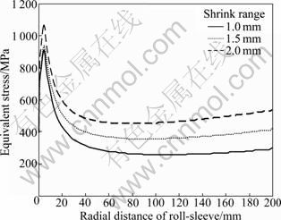
Fig. 10 Equivalent stress distribution of points along radial direction of roll sleeve
3 Life calculation
For built-up sleeved backup roll, it not only bears the shrink fit stress, but also the tremendous rolling stress. In the rolling contact area, the roll surface stresses generate abrupt change, which will greatly reduce the service life of the backup roll. Usually, the roll surface scaling and fatigue cracks are the principal failure forms of roll [18-19]. In addition, after rolling for a period of time, the roll sleeve becomes thinner for wear and the connection power between roll sleeve and roll core would become smaller, so self-evident and sliding failure may occur if the interface pressure is not sufficient to prevent relative circumferential slip between the sleeve and the core. However, this also cannot be ignored.
It can be found that the maximum stress value of backup in rolling process does not exceed the yield limit of the roll material, belonging to high-cycle life. The fatigue equations for estimating the fatigue life of roll were provided by Refs. [20-21] as
Nf=A[����-����c]-2 (1)
where Nf means fatigue life; ���� means strain increment; ����c means theory strain fatigue limit; A means strain fatigue resistance coefficient, a constant related with tensile properties:
����c=2��-1/E-��f/103.5 (2)
where E means elastic modulus; ��-1 means fatigue limit; ����f means fracture ductility coefficient.
 (3)
(3)
��f=-ln(1-��k) (4)
where ��k means contraction of cross sectional area.
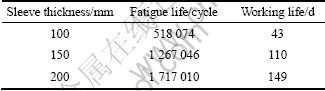
According to the working characteristics and failure form of backup roll, the roll materials [22] were selected as follows: roll sleeve 4Cr5MoV1Si and roll core 35CrMo. Besides, the work roll material was 60CrMnMo. Based on the curve of stress-strain of roll calculated in the previous sections, the fatigue life of backup roll with different sleeve thicknesses can be estimated when the shrink range is 2 mm. The properties of these materials are described in Ref. [23]. For the roll sleeve material, elastic modulus E=2.1��105 MPa, fatigue limit ��-1= 670 MPa, fracture ductility coefficient ��k=0.55, where the working life under the rolling speed of 1 m/s, is 20 h per day.
Table 3 gives the working life of built-up sleeved backup roll with different sleeve thicknesses. From Table 3, it can be found that roll sleeve thickness has a great influence on built-up sleeved roll work life. As the roll sleeve thickness increases, the roll work life is higher. The results computed by the simulations and theory show a good agreement with data obtained in production, which is supplied by Tianjin Steel Rolling Mill.
Table 3 Fatigue life of built-up sleeved backup roll
4 Conclusions
1) In the same shrink range, stresses along the roll sleeve radial direction resulting from the internal pressures exhibit a linear relationship. When the rolls have different sleeve thicknesses, the thicker sleeve keeps lower stress at the surface of roll sleeve, but the inner surface stresses change little. However, with the same sleeve thickness, the equivalent stress is directly proportional to the shrink range. Therefore, the choice of the appropriate shrink range is the key to the successful application of built-up sleeved backup rolls.
2) The sleeve thickness has little influence on the roll surface and inner stress perk value, while the stress has a large growth on the basis of shrink fit stress with the shrink range increasing. The stresses located in the depth of 3-6 mm away from the roll sleeve surface reach the maximum value, which will be bad for fatigue life of roll. Therefore, under the circumstance of ensuring transferring enough torque, the shrink range should be keep smaller.
3) The roll sleeve thickness is larger, and the logarithmic strain of the roll inter surface varies less, which will be beneficial for the roll life. Therefore, with strength and technology permitting, the thicker roll sleeve should be selected, which can also reserve sufficient grinding allowance for the roll.
References
[1] DONG Qi. Improvement of heat treatment of roll sleeve of backup roll [J]. Cfhi Technology, 2008, (1): 26-27. (in Chinese)
[2] SUN Deng-yue. A big internal cooled backup roll with numbers of sleeves assembled together, China Patent 200720138493.0 [P]. 2009.
[3] JONES R M F, KENNEDY R L. Processing and properties of spray formed hss rolling mill roll sleeves [J]. Metal Powder Report, 2000, 6(55): 38.
[4] QIAO Shu-jun, LIU Dong-hai, WANG Pei-xun, WU Chang-hao, ZHANG Yong-sheng. The manufacturing of the compound bushing rolls [J]. Heavy Casting and Forging, 2006, 2(2): 22-23. (in Chinese)
[5] JI Kai. Study on roller repairing technology [J]. Mechanical Management and Development, 2004, (2): 12-13. (in Chinese)
[6] BRENNAN F P, NGIAM S S, LEE C W. An experimental and analytical study of fatigue crack shape control by cold working [J]. Engineering Fracture Mechanics, 2008, 75(3): 355-363.
[7] RAD H R B, MONSHI A, IDRIS M H, ABDUL KADIR M R, JAFARI H. Premature failure analysis of forged cold back-up roll in a continuous tandem mill [J]. Materials and Design, 2011, 32(8/9): 4376-4384.
[8] ARIF A F M, OVAISULLAH K, SHEIKH A K. Roll deformation and stress distribution under thermo-mechanical loading in cold rolling [J]. Journal of Materials Processing Technology, 2004, 147(2): 255-267.
[9] BENASCIUTTIA D, BRUSAB E, BAZZAROC G. Finite elements prediction of thermal stresses in work roll of hot rolling mills [J]. Procedia Engineering, 2010, 2(1): 706-716.
[10] YUN M, LOKYER S, HUNT J D. Twin roll casting of aluminium alloys [J]. Materials Science and Engineering A, 2000, 280(1): 116- 123.
[11] SHU Zhao-hui, TANG Wei-lin, FEI Xiao-ping. Stress analysis and shrink range optimal design for built up composite sleeved roll in H beam mill [J]. Steel Rolling, 1994, (3): 7-12. (in Chinese)
[12] TRUMAN C E, BOOKER J D. Analysis of a shrink-fit failure on a gear hub/shaft assembly [J]. Engineering Failure Analysis, 2007, 14(14): 557-572.
[13] YU Han-qing, LI Xiao-pei, ZHAO Bing-hou. Calculation and selection guide of shrink range [M]. Beijing: China Standards Press, 1990: 21-23. (in Chinese)
[14] ZHANG Yu, MCCLAIN B. Design of interference fits via finite element method [J]. International Journal of Mechanical Sciences, 2000, 42(9): 1835-1850.
[15] IQUCHI, TAKAAKI, YARITA, IGUCHI T, YARITA I. 3-dimensional analysis of flat rolling by rigid-plastic FEM considering sticking and slipping frictional boundary [J]. ISIJ International, 1991, 31(6): 560-565.
[16] SUN Deng-yue, WEI Zhi-he, ZHOU Hui-feng. The research of big internal cooled backup roll with numbers of sleeves assembled together [C]// Applied Mechanics and Mechanical Engineering: Trans Tech Publications, China, 2009: 1203-1207.
[17] SUN Deng-yue, ZHANG Yuan-fang, ZHA Xian-wen, LIU Wen-wu, MA Hui-wen. Study on the roller��s thermal stress of the liquid core heavy reduction rolling mill [C]. Applied Mechanics and Materials, 2010: 1380-1384.
[18] YU Bing, ZHOU Bo. Anti-peeling off research and optimization design on the supporting roller of continuous hot rolling mill [J]. Journal of Machine Design, 2008, 25(3): 10-12. (in Chinese)
[19] HUANG Qing-xue, WANG Jian-rnei, MA L-feng, ZHAO Chun-jiang. Fatigue damage mechanism of oil film bearing sleeve [J]. Journal of Iron and Steel Research, International, 2007, 14(1): 60-63, 68.
[20] ZHENG Xiu-lin. Quantitative theory of metal fatigue [M]. Xi��an: Northwestern Polytechnical University Press, 1994: 8-41. (in Chinese)
[21] JEN Yi-ming, YIP Ming-chuen, WEI Cheng-long, SUO Guo-ching. Prediction of low-cycle contact fatigue life of sleeve�Cpin�Cshaft connections under axial and torsional cyclic loading [J]. International Journal of Fatigue, 2007, 29(5): 796-809.
[22] SUN Deng-yue, ZHANG Yuan-fang, ZHA Xian-wen, LIU Wen-wu, MA Hui-wei, FAN You-qin. Analyzing of the thermal stress and fatigue life of the liquid core heavy reduction rolling mill��s roller [C]. Applied Mechanics and Materials, 2011: 166-170.
[23] LU Hui-ming, CHEN Yun-yuan. Mechanical engineering material properties data manual [M]. Beijing: China Machine Press, 1994: 441-726. (in Chinese)
(Edited by DENG L��-xiang)
Foundation item: Project(E2010001155) supported by the Natural Science Foundation of Hebei Province, China
Received date: 2011-06-27; Accepted date: 2011-12-29
Corresponding author: SUN Deng-yue, Professor, PhD; Tel: +86-13582403079; E-mail: sdy@ysu.edu.cn

