
Microstructure and formation mechanism of
in-situ TiC-TiB2/Fe composite coating
WANG Zhen-ting(王振廷), ZHOU Xiao-hui(周晓辉), ZHAO Guo-gang(赵国刚)
College of Materials Science and Engineering,
Heilongjiang Institute of Science and Technology, Harbin 150027, China
Received 19 November 2007; accepted 4 April 2008
Abstract: Steel matrix composite coatings locally reinforced with in situ TiC-TiB2 particulates were prepared by argon arc cladding(AAC) with different mass fractions of Fe and Ti+B4C powders as the binding materials. The microstructure, micro-hardness and wear resistance were investigated using SEM, XRD, Micro-hardness Tester, and Friction and Wear Tester, respectively. The results show that the main phases of coating are TiC, TiB2 and α-Fe. The excellent metallurgical bonding is formed between the composite coating and substrate. The coating is uniform, continuous and almost defect-free and the particles are dispersively distributed in the cladded coating. Moreover, the formation mechanism was investigated. With the increase of the content of TiC+TiB2, the micro-hardness and wear resistance are also improved at the room temperature under normal atmosphere conditions.
Key words: TiC-TiB2; argon arc cladding; microstructure; formation mechanism
1 Introduction
Titanium alloy matrix composites have received considerable interest due to their high strength/mass ratio, elevated temperature resistance and excellent corrosion resistance[1-3]. Recently, however, iron and steel matrix composites reinforced with in situ synthesized ceramic particulates have been the subject of significant investigation, which have low costs and exhibit good mechanical properties[4-5]. Among these ceramic particulates, TiC and TiB2 are obtaining more attention due to their high melting points, low densities, good thermal and chemical stability, and high hardness[5-6]. These facts make them attractive as aircraft propulsion systems and cutting tools. Moreover, they can be used as cathodes for Hall-Heroult cell due to their good electrical conductivity[7-9].
Several methods have been used for the preparation of TiC-TiB2 compositions, such as mechanical alloying [7], spark plasma synthesis(SPS)[8], high-energy ball milling[9], and self-propagating high temperature synthesis(SHS) [10-11]. Mechanical alloying was used to synthesize TiC-TiB2 composites after milling for 90 min[7], and with further milling, the diameters of the composite powder rarely change but the crystallinic sizes decrease gradually. The SPS was used to synthesize dense TiC-TiB2 composites starting from Ti, C and B4C powders by LOCCI et al[8] who obtained a pure dense product(relative density 98%). It can be seen that the researches of TiC-TiB2 mainly focus on composites, and there are few coatings.
Argon arc cladding (AAC) is a new method for fabricating composition, which uses tungsten inert gas welding(TIG). Compared with those methods mentioned, the equipment of AAC is cheaper, easy to operate and popularize, and has engineering practical value[12-15]. Recently, new attempts have been made using AAC to achieve surface composites or surface alloying[16-17]. WANG et al[17] investigated the multi-pass overlapping gas tungsten arc welding (GTAW) with graphite and ferrotitanium (Fe, Ti) on AISI 1020 steel, and the composite coating exhibited high hardness and excellent wear resistance. Up to now, there has no report about in-situ synthesized TiC-TiB2/Fe composite coating using argon arc cladding(AAC). In this work, in-situ TiC-TiB2/Fe composite coating was synthesized using AAC, which can provide basic experimental and academic reference, at the same time, the microstructure and formation mechanism were investigated as well.
2 Experimental
Q235 steel was used as the substrate material, and the dimension was 40 mm×20 mm×10 mm. The starting materials were Ti 99.5%, B4C 99.5% and Fe powders, and the component ratios of coatings are listed in Table 1. The total mass of every sample was 4 g. The powders were mixed symmetrically to make up a powder mixture as the raw coating alloy. Then the mixed powders were pre-placed on the surface of Q235 steel using as a small amount of soluble glass as possible to keep the powders on the surface of the substrates tight. Powders and substrates were thoroughly cleaned, dried and finally rinsed by acetone with the thickness of about 1 mm, and left about 1 mm of either end as the place to ignite arc. The samples were first put in the ventilated place at the room temperature for 24 h and then dried at 100 ℃ for about 1 h by DZ-2BC Vacuum Dryness Oven. Then coatings were carried out by MW3000 Digital Tungsten Inert Gas welding(TIG) machine with the operating welding current 140 A, welding voltage 20-22 V, argon flow rate 10 L/min, and welding speed 125 mm/min. The TIG welding process is shown in Fig.1[18].
Table1 Component ratios of coating (mass fraction, %)
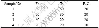
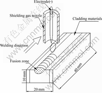
Fig.1 Schematic representation of TIG welding clad process and coating layer
The microstructures of coatings were examined with MX-2 600Fe scanning electron microscope(SEM), energy dispersive spectrometer(EDS) and a type of XD-2 X-ray diffractometer(XRD) with Cu Kα radiation operated at 36 kV and 30 mA was used to analyze the coating phase structure. Micro-hardness along the depth of the cross-section was measured using a MHV2000 type micro Vickers. The load was 1.9614 N and loading time was 10 s. An average value of hardness was taken from five different measurements. Abrasive wear experiments were done without lubrication at the room temperature and normal atmosphere conditions using a friction and wear tester (Model MMS-2A). The ring material of the wear couple was GCr15. The outer radius of the circular test ring was 40 mm. The test specimens were machined with size of 8 mm×5 mm×10 mm. The wear conditions were a normal load of 200 N, a sliding speed of 200 r/min, and the time of abrasion of 120 min.
3 Results and discussion
3.1 Microstructure
Fig.2 shows the XRD pattern of the locally reinforced Q235 steel composite coating using 70(Ti+B4C)-30Fe. The XRD results reveal that the coating mainly consists of TiC, TiB2 and α-Fe, without TiB and Ti3B4 transient compounds.
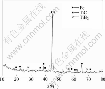
Fig.2 XRD pattern of AAC composite coating
Fig.3 shows the cross-section micrograph of coating. It can be clearly seen that the coating has a good quality, and there are no pores or cracks. The coating has metallurgical bonding with the base material, and the thickness of coating is about 0.8-1 mm. In the interface area, there exists a little reinforcement, conversely there’s more in the middle of coatings, where the particles distribute homogeneously. During AAC process, the dilution ratio of the region near substrate is lager than that of the middle region, so there are more particles in the middle area.
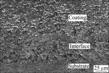
Fig.3 SEM micrograph of coating
Fig.4 reveals a relatively uniform distribution of TiC and TiB2 in the composite coatings. TiB2 particles exhibit clubbed shapes, whereas the cubic particulates are TiC. It can be seen from Fig.4, with the increase of (Ti+B4C) content, the size of TiB2 decreases. The volume fraction of TiC-TiB2 is about 28%-63%, which is calculated by coxpix simple PCI(USA) picture analysis software, and it increases with increasing the mass fraction of (Ti+B4C).
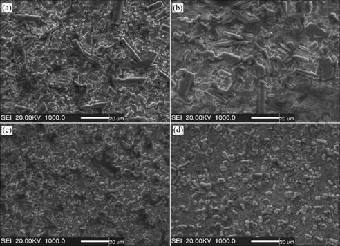
Fig.4 Typical microstructures of reinforced steel matrix coating fabricated using Fe-Ti-B4C systems with different mass fractions of Fe: (a) 70%; (b) 60%; (c) 50%; (d) 30%
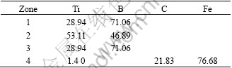
Fig.5 shows the scanning electron micrograph of sample 4, together with EDS(see Table 2). It can be seen that the hexagonal and clubbed particles are TiB2 with the length of 5-10 μm, whereas the cubic and petaloid particles are TiC with the length of 1-3 μm, moreover, most TiB2 particles have a clubbed structure, and the substrate is α-Fe. The calefactive and refrigerant speeds are very high, and there is some unreacted Ti that dissolves into α-Fe. The argon arc has large dilution ratio. Together with effect of arc whisking, arc driving and gravity make Fe of base metal come into fused area, which reduces the hardness of coating.
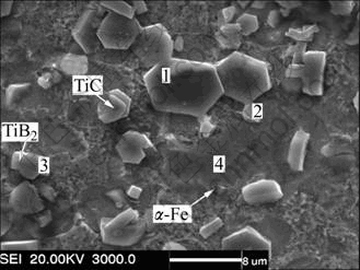
Fig.5 SEM micrograph of coating
Table 2 EDS result (mass fraction, %)
3.2 Formation of TiC and TiB2 particles
A kinetic investigation performed allows us to conclude that solid-state diffusion is the mechanism governing the synthesis process[5,8,19-20]. ZHAO and CHENG[20] suggested two reaction paths:
Path I:
Ti+B4C=TiC+TiB (1)
TiB+B4C=TiC+TiB2 (2)
Path II:
Ti+B4C=TiC+TiB (3)
16TiB+B4C=5Ti3B4+TiC (4)
3Ti3B4+B4C=8TiB2+TiC (5)
At the beginning, B4C was surrounded by Ti powders. When the arc reacted with the layer, the layer absorbed much energy and melted quickly. Because Fe has good fusibility and low melting temperature (1 538 ℃), it would melt firstly, which made [Ti+B4C] immerse into Fe fusant. At the interface between Ti and B4C particles, initial atomic diffusion facilitated Ti-containing compounds to form, following reaction(1). The diffusivity of carbon was significantly greater than
that of boron[21]. Thus, carbon readily combined with titanium to yield TiC at first. But a concentration gradient of boron existed along the diffusion path between Ti and B4C particles, resulting in the formation of TiB. Ti3B4 and TiB2 phases depended on the mass ratio of Ti to B. At higher temperatures, reaction path I was most likely to become dominant without the transit phase Ti3B4 due to rapid diffusion, leading to a large amount of intermediate phase TiB. Moreover, Ti3B4 was the unstable phase in thermodynamics, which could exist at lower temperature, whereas AAC exhibited high reaction temperature, so we could believe it followed path I in this work. According to XRD, the transit phase TiB converted into TiB2 absolutely. Fig.6 shows the schematic drawing of the reaction[19].
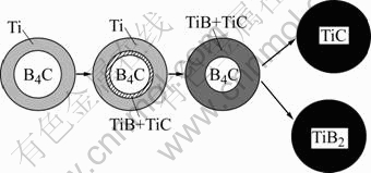
Fig.6 Schematic drawing of reaction
At the beginning of AAC, there was more TiC, and the growth rate of TiB2 was limited, so TiB2 grew between the gap of TiC. The TiB2 that had nucleated early had more time to grow to its crystal structure, which determined the growth pattern as hexagonal prism morphology. With increasing the temperature and holding time, there was more TiB2. Most TiB2 particulates had a clubbed structure because TiB2 particulates had enough space to grow amply between TiC particulates. From the XRD pattern, it can be seen that the diffraction peak of TiB2 is higher than that of TiC. This is consistent with theoretical arithmetic of the following chemical reaction:
3Ti+B4C=TiC+2TiB2 (6)
3.3 Hardness and wear resistance
Fig.7 shows the curves of micro-hardness profiles of AAC samples along the depth of cross-section. It can be seen that with the increase of (Ti+B4C) content, the micro-hardness also increases, which is attributed to the increase of hard TiC-TiB2 ceramic particulates. Sample 4 has the highest hardness, which can reach HV0.2 900 four times higher than that of substrate. The surface of coating contacted arc directly, the elements volatilized and overburned seriously, which resulted in the micro- hardness rising from exterior surface to interior, up to the culmination, then decreasing mildly. Between the place of coating and substrate, micro-hardness declines quickly, and reaches the rock bottom at substrate.
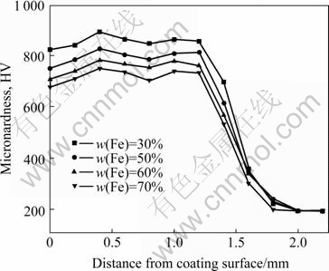
Fig.7 Microhardness curves of AAC
Fig.8 shows the wear loss of composite coatings and Q235 steel. It is clear that wear loss of coatings is smaller than that of Q235 steel, and the wear loss of sample 4 is the smallest, which has the same reason with micro-hardness. It can be seen that: 1) There are many TiC and TiB2 particulates, which are dispersively distributed in the coating, resulting in dispersion strengthening; 2) AAC has rapid cooling rate, arousing cryptomere strengthening; 3) In-situ TiC and TiB2 particulates metallurgically bond to the base material; 4) There are many clubbed TiB2 particulates, which is very useful for improving the mechanical properties of TiC/TiB2 ceramics[22]. This is because the 1?2 molar ratio of TiC to TiB2 can weaken the high thermal expansion effect of excessive TiC content and reduce the thermal stresses; however, compared with the formation of pure TiB2, this can decrease the high reaction heat, which can reduce the porosity caused by the gas volatilization[5].
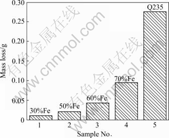
Fig.8 Wear loss of AAC coating and Q235 steel
4 Conclusions
1) Fe based metallic ceramic coating reinforced by in-situ synthesized TiC and TiB2 particles was prepared on the surface of Q235 steel by argon arc cladding(AAC) using different mass fractions of Fe and Ti+B4C powders as the binding materials. The thickness of coating is about 0.8-1 mm. The volume fraction of TiC-TiB2 is about 28%-63% and increases with increasing the mass fraction of Ti+B4C. With the increase of Ti+B4C, the volume fraction of TiC-TiB2 increases as well.
2) Solid-state diffusion is the mechanism governing the synthesis process. TiC is the first phase formed, and exhibits cubic and petaloid shapes. While TiB2 formation occurs afterward, which presents hexagonal and clubbed forms. And there are not TiB and Ti3B4 transient composites.
3) Sample 4 has the highest micro-hardness and best wear resistance due to more TiC-TiB2 ceramic particulates, and the highest hardness is up to HV0.2900, four times higher than that of the substrate.
References
[1] WANG Xiang, GAI Peng-tao. Effect of carbon content on microstructure and property of TiC/Ti-6Al-4V composites [J]. Trans Nonferrous Met Soc China, 2007, 17: s546-s550.
[2] WU Wang-liang, SUN Jian-feng, DONG Sheng-min, LIU Rong-xiang. Influence of processing parameters on microstructure and wear resistance of Ti+TiC laser clad layer on titanium alloy [J]. Trans Nonferrous Met Soc China, 2006, 16: s2096-s2099.
[3] ZHANG Er-lin, JIN Yun-xue, ZENG Song-yan, ZHU Zhao-jun. Microstructure of in-situ TiC particle reinforced titanium alloy matrix composites [J]. Trans Nonferrous Met Soc China, 2000, 6(10): 764-768.
[4] WANG H Y, HUANG L, JIANG Q C. In situ synthesis of TiB2-TiC particulates locally reinforced medium carbon steel-matrix composites via the SHS reaction of Ni-Ti-B4C system during casting [J]. Mater Sci Eng A, 2005, 407: 98-104.
[5] YANG Ya-feng, WANG Hui-yuan. Fabrication of steel matrix composites locally reinforced with different ratios of TiC-TiB2 particulates using SHS reactions of Ni-Ti-B4C and Ni-Ti-B4C-C systems during casting [J]. Mater Sci Eng A, 2007, 445/446: 398-404.
[6] LOCCI A M, ORR`U R, CAO G. Effect of ball milling on simultaneous spark plasma synthesis and densification of TiC-TiB2 composites [J]. Mater Sci Eng A, 2006, 434: 23-29.
[7] ZHAO Kun-yu, ZHU Xin- kun, CHENG Bao-chang, LIN Qiu-shi, ZHANG Xiu-qing CHEN Tie-li, SHU Yun-shen, YONG Qi-long. Synthesis of TiB2+TiC by mechanical alloying [J]. Trans Nonferrous Met Soc China, 2001, 11(1): 135-137.
[8] LOCCI A M, ORR`U R, CAO G, MUNIR Z A. Simultaneous spark plasma synthesis and densification of TiC-TiB2 composites [J]. J Am Ceram Soc, 2006, 89: 848-855.
[9] LEE J W, MUNIR Z A, OHYANAGI M. Dense nanocrystalline TiB2-TiC composites formed by field activation from high-energy ball milled reactants [J]. Mater Sci Eng A, 2002, 325: 221-227.
[10] ZHANG Xing-hong, ZHU Chun-cheng, QU Wei-a. Self-propagating high temperature combustion synthesis of TiC/TiB2 ceramic-matrix composites [J]. Composites Science and Technology, 2002, 62: 2037-2041.
[11] HUANG L, WANG H Y, QIU F. Synthesis of dense ceramic particulate reinforced composites from Ni-Ti-C, Ni-Ti-B, Ni-Ti-B4C and Ni-Ti-C-B systems via the SHS reaction, arc melting and suction casting [J]. Mater Sci Eng A, 2006, 422: 309-315.
[12] KORKUT M H, YILMAZ O, BUYTOZ S. Effect of aging on the microstructure and toughness of the interface zone of a gas tungsten arc(GTA) synthesized Fe-Cr-Si-Mo-C coated low carbon steel [J]. Surf Coat Technol, 2002, 157: 5-13.
[13] ERO?LU M, ?ZDEMIR N. Tungsten-inert gas surface alloying of a low carbon steel [J]. Surf Coat Technol, 2002, 154: 209-217.
[14] BUYTOZ S, ULUTAN M. In situ synthesis of SiC reinforced MMC surface on AISI 304 stainless steel by TIG surface alloying [J]. Surf Coat Technol, 2006, 200: 3698-3734.
[15] MRIDHA S, ONG H S, POH L S. Intermetallic coatings produced by TIG surface melting [J]. Mater Process Technol, 2001, 113: 516-520.
[16] WANG X H, SONG S L, ZOU Z D. Fabricating TiC particles reinforced Fe-based composite coatings produced by GTAW multi-layers melting process [J]. Mater Sci Eng A, 2006, 441: 60-67.
[17] WANG X H, SONG S L, QU S Y. Characterization of in situ synthesized TiC particle reinforced Fe-based composite coatings produced by multi-pass overlapping GTAW melting process [J]. Surface & Coatings Technology, 2007, 201: 5899-5905.
[18] BUYTOZ S, ULUTAN M, MUSTAFA Y M. Dry sliding wear behavior of TIG welding clad WC composite coatings [J]. Applied Surface Science, 2005, 252: 1313-1323.
[19] KLINGER L, GOTMAN I, HORVITZ D. In situ processing of TiB2/TiC ceramic composites by thermal explosion under pressure: Experimental study and modeling [J]. Mater Sci Eng A, 2001, 302: 92-99.
[20] ZHAO Hong, CHENG Yi-Bing. Formation of TiB2-TiC composites by reactive sintering [J]. Ceramics International, 1999, 25: 353-358.
[21] LASKAR A L, BOCQUET J L, BREBEC G. Diffusion in materials [M]. Netherlands: Kluwer, Dordrecht, 1990.
[22] ZHANG X H, ZHU C C, QU W. Self-propagating high temperature combustion synthesis of TiC/TiB2 ceramic-matrix composites [J]. Comp Sci Tech, 2002, 62: 2037-2041.
Foundation item: Project(50075085) supported by the National Natural Science Foundation of China; Project supported by Heilongjiang Postdoctoral Grant of China
Corresponding author: WANG Zhen-ting, Tel: +86-451-88036216: E-mail: wangzt2002@163.com
(Edited by LI Xiang-qun)

