
Continuous and directional solidification technology of titanium alloys with cold crucible
CHEN Rui-run(陈瑞润), DING Hong-sheng(丁宏升), GUO Jing-jie(郭景杰),
BI Wei-sheng(毕维生), FU Heng-zhi(傅恒志)
School of Materials Science and Engineering, Harbin Institute of Technology, Harbin 150001, China
Received 20 April 2006; accepted 30 June 2006
Abstract: The experiments of continuous and directional solidification of titanium alloys with cold crucible were carried out in a multifunctional electromagnetic cold crucible apparatus. Parameters and factors influencing the surface crack and macrostructure of titanium alloy ingots were studied. The mechanism of the parameters and factors influencing the surface crack and macrostructure of the ingots were interpreted. The results show that the surface cracks of the prepared ingots decrease with the increase of the input power from 50 to 60 kW or with the increase of the coil turns from 3 to 5 circles. The surface cracks increase with the increase of withdrawal velocity from 3 to 5 mm/min or the height of the primer from 2 to 3 cm, then decrease with the increase of withdrawal velocity from 5 to 8.7 mm/min or the height of the primer from 3 to 4 cm. Coil turns is the most important one in all parameters effect on the surface crack, the input power is more important, then the withdrawal velocity is important and the height of the primer is the least important. Withdrawal velocity is the most important factor affecting the macrostructure, and effects of other factors on macrostructure is slight. With the decrease of velocity from 8.7 to 0.5 mm/min, the quantity of grains reduces, the grain orientation degree becomes small, and the solidification fronts change from concave to plane to convex. The ingot can be directional solidified at velocity of 1 mm/min. The ingot with free surface crack and directional macrostructure is prepared under definite conditions.
Key words: Ti6Al4V alloys; cold crucible; continuous casting; directional solidification
1 Introduction
Titanium-based alloys are promising materials, which are applied to aerospace and shipbuilding industries owning to their high specific strength, hot resistance and corrosion resistance[1]. However, there are some difficulties in controlling the chemical elements and temperature in melting titanium-based alloys because of their high melting point, chemical activity and the differences of physical properties in high temperature. Water-cooled cold crucible provides an effective method for melting titanium-based alloys[2]. Cold crucible continuous casting and directional solidification is a technology that combines the advantages of cold crucible technology, continuous casting and directional solidification. The process is that the charge in the segmented crucible is melten in high frequency magnetic field, and the alloy melt are kept at soft contact state with crucible wall because of electromagnetic force, then continuous casting and directional solidification is realized.
Cold crucible continuous casting and directional solidification can realize high pure melting in rapid speed, control the structure and the shape, shorten times and save energy for the second times heating[3].
Continuous casting of titanium alloy billets with cold crucible was reported[4-7]. Steel ingots and aluminium ingots with crack free and preferable structure were continuous cast by cold crucible technology in China[8-14], but there is few report about directional solidification with cold crucible in available information.
FU Heng-zhi put forward continuous casting and directional solidification of titanium alloys with cold crucible. This technology not only breakthroughs the disadvantage of only directional solidifying low melting point metal or alloys in the past, but also integrates alloy melting, continuous casting and directional solidification, so develops the directional solidification technology.
Cold crucible continuous casting and directional solidification is different from hot mold continuous casting and other directional solidification technology, because it is influenced by electromagnetic field, temperature field, fluid field and so on, and the crucible wall is cold, therefore, the requirements for optimizing technological parameters are more strict. This paper analyzed the process of parameters affecting on hot crack and directional solidified structure based on experiments and theory analyse, and concluded some rules about cold continuous casting and directional solidification.
2 Experimental
2.1 Experimental apparatus and materials
A multi-function continuous casting and directional solidification apparatus is used in this study, which is devised by HIT, as shown in Fig.1.
This apparatus is composed of melting system, controlling system, cooling system and vacuum system.
Melting system includes a copper crucible and a induction coil. The crucible has eight water cooled segments, and special insulation materials is filled between segments. Induction coil is made of copper pipe with diameter of 10 or 8 mm, which is connected with the power and can induce high frequency magnetic field.
Controlling system includes materials supplying system, withdrawal system which can control supplying and withdrawal velocity separately, and the power controlling system which can regulate power voltage, electric current and power frequency.
Vacuum system is composed of mechanical pump, diffusion pump and argon charging equipment, which can establish a vacuum degree and provide argon protection in the chamber.
Cooling system includes water cooled part for melting and power system, and Ga-In liquid cooled part for directional solidification of titanium alloys.
The materials used in this experiment is Ti6Al4V alloys.
2.2 Experimental design
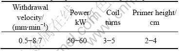
The aim of cold crucible continuous casting and directional solidification is casting titanium billet with defect-free surface and directional-solidified macrostruc- ture. There are many parameters affecting on surface quality and macrostructure. Four main kinds of technological parameters are decided after a lot of preparing experiments, and they are withdrawal velocity, electrical power, coil turns and primer height. In order to obtain the rules of technological parameter affecting on the surface quality and the macrostructure, Table 1 is designed according to experiment rules, and different billets are directional solidified.
Table 1 Technological parameters of orthogonal experiment
3 Results
The rules of the parameters effect on the hot crack and the macrostructure are concluded by the way of orthogonal experiment.
3.1 Effect of technological parameters on surface quality
Fig.2 shows the macrostructure of the typical billets cast by continuous casting and directional solidification under different parameters of the orthogonal experiment. It can be seen that the billets are different under different parameters. In horizontal direction hot cracks appear on the surface shown in Figs.2(a), (b) and (c), and crack free on the surface shown in Figs.2(d) and (e), but much cracks on the surface shown in Fig.2(b) and seldom cracks on the surface shown in Figs.2(a) and (c). There

Fig.1 Scheme of multi-function continuous casting and directional solidification apparatus: (a) process; (b) cross section of cold crucible
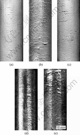
Fig.2 Different billets cast under different parameters (withdrawel velocity(mm/min)/power(kW)/coil turns/primer height(cm)): (a) 8.7/55/3/4; (b) 5/55/5/2; (c) 3/55/4/3; (d) 1/49/4/3; (e) 0.5/49/4 /3
are some marks arising from the crucible slits in perpendicular direction.
The length of hot crack is taken as index for evaluating surface quality, because hot crack is the main defect on the billet surface, and the width of hot cracks are almost equal. The length of hot crack is measured on the surface of all billets in 50 mm length. Effect of technological parameters on the surface quality is inferred according to the length of hot crack, as shown in Fig.3. It can be seen that the effect of different parameters on the hot crack is different, coil turn is the most important factor, power is more important, withdrawal velocity is important, and the primer height is the least important. The length of hot crack increases in the beginning, and then decreases with the increase of withdrawal velocity or primer height, but it increases with the increase of power or coil turn.
3.2 Effect of technological parameters on macro- structure
Billets cast under different conditions are sectioned longitudinally, and those sections are polished and etched by HF+HNO3+H2O solution. Microstructures are shown in Fig.4. It can be seen from Fig.4 that macrostructure are different under different parameters. Grain size and grain growth direction are distinguished very much.
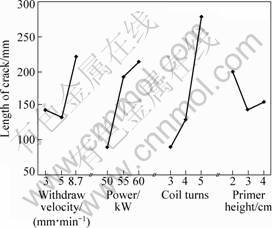
Fig.3 Effect of technological parameters on hot crack

Fig.4 Microstructures of billets cast under different parameters (withdrawel velocity(mm/min)/power(kW)/coil (turns)/primer height(cm)): (a) 8.7/55/3/4; (b) 5/55/5/2; (c) 3/55/4/3; (d) 1/49/4/3; (e) 0.5/49/4 /3
Grain size changes from little crystal to almost a single crystal, and grain growth direction changes from about 45? to 0? deviating axial direction. Planar interface appears and the macrostructure is directional solidified in Fig.4(d), and the interface protrudes to the liquid and the billet is almost a single crystal in Fig.5(e). Grain size is taken as index for evaluating microstructure, and effect of technological parameters on microstructure can be concluded, as shown in Fig.5. From this figure, withdrawal velocity is the most important factor in those four factors on the macrostructure, and grain size increases with the increase of withdrawal velocity.

Fig.5 Effect of parameters on the macrostructure
3.3 Optimizing technological parameters
According to the mechanism of hot crack forming, hot crack will be formed when the friction between the skull and the cold crucible inner wall is bigger than the strength that the skull can bear. In order to decrease hot crack, the friction should be decreased. Based on the effect of parameters on the hot crack and the macrostructure, some measurements are taken in the experiment: the cold crucible inner wall is coated in order to decrease the friction, and the withdrawal velocity is lowered such as 1.0 and 0.5 mm/min in order
to obtaine directional solidified macrostructure. The billets and the macrostructure are shown in Figs.2(e), 2(f) and Fig.4 respectively. The billets are crack free and the macrostructure are directional solidified.
4 Discussion
4.1 Effect of technological parameters on hot crack
Fig.6 shows the scheme of hot crack forming. Hot crack forming is decided by the height of the meniscus (hm), the height of three phase line (ht, the line of the liquid, the solid and the gas intersection) and the height of the skull (hs). Hot crack will increase when any of three kinds of height increases.
4.1.1 Effect of coil
The change of the coil will change the distribution of the electromagnetic field in the crucible, and influence the interaction of the skull and the crucible inner wall. Fig.7 shows the computed magnetic field by mutual inductance coupling model under the condition of power of 50 kW, and the coil turns of 3, 4 and 5. It can be seen that magnetic intensity increases with the increase of coil turn, and this will increase induction heating, so hot crack increases.
4.1.2 Effect of power
The change of the power will influence the magnetic field strength. Fig.8 shows the magnetic field when the model is the same as Fig.7 under the condition of three turns coil and the power of 50, 55 and 60 kW. It can be seen that the maximum of the magnetic field strength increases, but the position of the maximum is not moved with the increase of the power. In the experiments, the height of three phase lines (ht) decreases a little, the height of the skull(hs) increases a lot and the width of the skull (ws) decreases with the increase of the power, so hot crack increases.
4.1.3 Effect of withdrawal velocity
The increase of the withdrawal velocity can
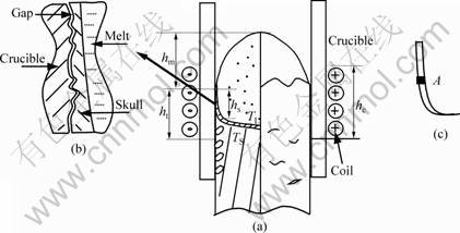
Fig.6 Scheme of hot crack formation: (a) influencing factors; (b) gap between crucible and skull; (c) a dot on skull

Fig.7 Variations of magnetic intensity under different conditions: (a) different coil turns; (b) different powers
influence the hot crack in two aspects: on one hand, the solidification interface descends (that is hs becomes bigger), and hot cracks increase; on the other hand, the reheating of the skull by the coil reduces, and hot cracks decrease. The reheating is dominant in those two respects when the withdrawal velocity is less than 5 mm/min, so the surface changes better; but the descent is dominant when the withdrawal velocity is more than 5 mm/min, so the surface changes better.
4.1.4 Effect of primer height
The primer height will change the volume of the melt meniscus, and this will influence ht and hs. TANAKA[15] computed the melt volume effect on the melt temperature and the solidification front. The results show that with the increase of the volume, ht changes little, but the reduction of the melt temperature will cause the solidification front to ascend, which means that hs decreases. When the primer height changes from 20 mm to 30 mm, the change of the melt temperature is very big, and this causes hs to decrease a lot, so hot cracks become less. When the primer height changes from 30 mm to 40 mm, the change of the melt temperature is very small, and hs decreases a little, but the change of ht is dominant in effecting on the hot crack, so hot cracks change more.
4.1.5 Different effects of technological parameters on hot crack
Hot crack is influenced by magnetic field strength and magnetic field distribution. Hot crack increases when magnetic field strength or magnetic field distribution change a lot. The computing results show that magnetic field strength reduces by about 20% and the position of the maximal magnetic field strength ascends about 10 mm when the coil turns change from 3 to 5 under 50 kW power. Magnetic field strength increases by about 10% when the power changes from 50 to 60 kW in 3 coil turns; the solidification front descends about 3 mm when withdrawal velocity changes from 3 to 8.7 mm/min; the solidification front ascends only a little when the primer height changes from 20 to 40 mm. So the effects of different technological parameters on hot crack are different: coil turn is the most important, power is more important, withdrawal velocity is important and the primer height is less important.
4.2 Effect of technological parameters on mic- rostructure
Macrostructure is decided by the solidification front which is influenced by technological parameters. The billet under the solidification front aparts from the cold crucible inner wall because of freezing shrinkage, and the heat of the melt is conducted by the skull which softly contacts with the inner wall by lateral heat transfer. Lateral heat transfer decreases about 90% under soft contact condition, so lateral heat transfer is very little in cold crucible continuous solidification.
Thermal coefficient of Ti6Al4V alloy is small (0-800 ℃,about 20 W/(m・K)), so the axial heat transfer is very little. The shape of the solidification front is influenced by two aspects when lateral heat transfer is steady: the solidification front will ascend because of axial heat transfer, and the solidification front will descend because of withdraw. The solidification front protrudes to the liquid at low velocity, because the ascending arising from axial heat transfer is bigger than the descending arising from withdraw. With the increase of withdrawal velocity, the solidification front descends more, and the solidification front is plane when the protruding is equal to the concave. With more increase of withdrawal velocity, the solidification is more concave. As shown in Fig.4, the solidification front protrudes to the liquid at velocity of 0.5 mm/min, and is plane at velocity of 1 mm/min, is concave at velocity of more than 1 mm/min. Grains are more when the solidification front is more concave. The solidification front is influenced by the power, the coil and the primer height through changing the melt temperature.
5 Conclusions
1) The effects of different technological parameters on hot crack are different: the coil is the most important, the power is more important, the withdrawal velocity is important and the primer height is less important. Hot cracks increase with the increase of the coil or the power, and it decreases at the beginning, then increases with the increase of the withdrawal velocity or the primer height.
2) The withdrawal velocity is the most important factor in all parameters affecting on the macrostructure, grain number reduces and the solidification front changes from concave to protruding with the decrease of withdrawal velocity.
3) The billet is directional solidified at velocity of 1 mm/min, and the billet is almost a single crystal at velocity of 0.5 mm/min.
4) The billet with crack free and directional solidified macrostructure can be cast with inner wall coated cold crucible at low withdrawal velocity.
Acknowledgements
This work was supported by the National Key Fundamental Research Development Program of China (G200067202-2) and by Natural Science Foundation of China (50395102).
References
[1] LUO Guo-zhen, ZHOU Lian, DENG Ju. Research and development of titanium in China[J]. Rear Metal Materials and Engineering, 1997, 26(5): 1-6. (in Chinese)
[2] GUO Jing-jie, SU Yan-qing. Analyzing of thermodynamics and dynamics in titanium alloys ISM melting[M]. Harbin Institute of Technology Press, 1998: 14. (in Chiinese)
[3] JIANG Bing-yu. Vacuum induction melting in a cold crucible[J]. Rear Metal Materials And Engineering, 1999, 28(2): 105-109.(in Chiinese)
[4] EHRE E. Characterization of multicrystalline silicon: comparison between conventional casting and electromagnetic casting processes[J]. Solar Energy Materials and Solar Cells, 1998, 53: 313-327.
[5] DOUR G, EHRET E, LAUGIER A, SARTI D, GARNIER M, DURAND F. Continuous solidification of photovoltaic multicrystalline silicon from an inductive cold crucible[J]. Journal of Crystal Growth, 1998, 193: 230-240.
[6] SZEKELYJEDS T E. Magnetohydrodynamics in process metallurgy[M]. SanDiego: TMS, 1992: 189-202.
[7] TANAKA T, KURODA A, KURITA K. Continuous melting of titanium alloy by inducton cold crucible[J]. ISIJ International, 1992, 32(5): 575-562.
[8] GUO Jing-jie, WANG Tong-min, SU Yan-qing, DING Hong-sheng, JIA Jun. Numerical simulation of temperature field of titanium melted in induction furnace with a water-cooled copper crucible[J]. Foundry, 1997(9): 1. (in Chiinese)
[9] SU Yan-qing, GUO Jing-jie, DING Hong-sheng. The evaporation of alloying element during vacuum melting of TiAl intermetallics[J]. Foundry, 1999, 3: 1. (in Chiinese)
[10] DING Hong-sheng, GUO Jing-jie, JIA Jun, SU Yan-qing. Microstructure and properties of Ti-6Al-4V alloy with cold-wall induction melting preparation[J]. Materials Science and Technology, 1999, (S1): 12.(in Chiinese)
[11] JIN Jun-ze, ZHANG Xing-guo, CAO Zhi-qiang, ZHU Xiao-ying. Study on technological parameters of EMC processing in all alloys [J]. Chinese Journal of Materials Research, 1996, 10(4): 397. (in Chiinese)
[12] HOU Xiao-guang, ZHANG Xing-guo, CAO Zhi-qiang, JIN Jun-ze. Study on compound inductor systems of steel EMC[J]. Journal of Dalian University of Technology, 2000(7): 447. (in Chiinese)
[13] DENG An-yuan, YU Guang-wei, JIA Guang-lin, HE Ji-cheng. Numerical simulation of three-dimensional meniscus shape in electromagnetic soft-contact mold[J]. Journal of Iron and Steel Research, 2001, 13(3): 10-14. (in Chiinese)
[14] DENG Kang, REN Zhong-ming, JIANG Guo-chang. numerical simulation and experiment analysis of electromagnetic continuous casting with soft-contact mould[J]. Acta Metallurgica Sinica, 1999, 35(10): 1112-1115. (in Chiinese)
[15] TANAKA T, KURITA K, KURODA A. Liquid metal flow with heat transfer in a cold crucible confined by a free surface and a solidification front[J]. ISIJ International, 1991, 31(12): 1416.
(Edited by CHEN Can-hua)
Corresponding author: CHEN Rui-run, PhD; Tel: 86-451-86412394; E-mail: chenruirun@163.com

