��ѧ����Ni-P/Ni-Mo-P�Ʋ�IJ���Ӧ����ʴ��Ϊ����
��Դ�ڿ����й���ɫ����ѧ��(Ӣ�İ�)2018���12��
�������ߣ����� Ǯ����
����ҳ�룺2499 - 2510
�ؼ��ʣ���ѧ������Ni-P/Ni-Mo-P˫�Ʋ㣻����Ӧ��������ѹ�۷�����ʴ��
Key words��electroless plating; Ni-P/Ni-Mo-P duplex coatings; residual stress; nano indentation; corrosion resistance
ժ Ҫ��ͨ����ѧ�������Ʊ�Ni-P��Ni-Mo-P ���Ʋ��Լ�����ɷ���ͬ��Ni-P/Ni-Mo-P˫�Ʋ㡣��������ѹ�۷���AFM���������Ʋ����ͽ���IJ���Ӧ�������õ绯ѧ�������Ʋ���10% HCl��Һ�еĸ�ʴ��Ϊ���Ի�öƲ����Ӧ���븯ʴ��Ϊ֮��Ĺ�ϵ����������� Ni-P���Ʋ��Ni-P/Ni-Mo-P˫�Ʋ����Ϊ����ѹӦ�����ֱ�Ϊ241�� 206 MPa��Ni-Mo-P���Ʋ���ֳ�257 MPa�IJ�����Ӧ��������ѹӦ����ֹ�Ʋ��п��������������Ʋ�������ԡ�Ni-P/Ni-Mo-P˫�Ʋ�����ǵĵ��Ʋ���и��õ���ʴ�ԡ����⣬�Ʋ��Ӧ��״̬Ӱ���丯ʴ��ʽ��
Abstract: Single Ni-P and Ni-Mo-P coatings as well as duplex Ni-P/Ni-Mo-P coatings with the same compositions were prepared by electroless plating. The residual stresses of the coatings on the surface and cross sections were measured by nanoindentation and AFM analysis, and the corrosion behaviour of the coatings in 10% HCl solution was evaluated by electrochemical methods, to establish the correlation between the residual stresses and corrosion behaviour of the coatings. The results showed that the single Ni-P and duplex Ni-P/Ni-Mo-P coatings presented residual compressive stresses of 241 and 206 MPa respectively, while the single Ni-Mo-P coating exhibited a residual tensile stress of 257 MPa. The residual compressive stress impeded the growth of the pre-existing porosity in the coatings, protecting the integrity of the coating. The duplex Ni-P/Ni-Mo-P coatings had better corrosion resistance than their respective single coating. In addition, the stress states affect the corrosive form of coatings.
Trans. Nonferrous Met. Soc. China 28(2018) 2499-2510
Hong LIU1, Dai-shu QIAN2
1. School of Mechanical and Automotive Engineering, Qilu University of Technology (Shandong Academy of Sciences), Ji��nan 250353, China;
2. Corrosion and Protection Centre, School of Materials, The University of Manchester, Manchester, M13 9PL, UK
Received 19 February 2018; accepted 30 June 2018
Abstract: Single Ni-P and Ni-Mo-P coatings as well as duplex Ni-P/Ni-Mo-P coatings with the same compositions were prepared by electroless plating. The residual stresses of the coatings on the surface and cross sections were measured by nanoindentation and AFM analysis, and the corrosion behaviour of the coatings in 10% HCl solution was evaluated by electrochemical methods, to establish the correlation between the residual stresses and corrosion behaviour of the coatings. The results showed that the single Ni-P and duplex Ni-P/Ni-Mo-P coatings presented residual compressive stresses of 241 and 206 MPa respectively, while the single Ni-Mo-P coating exhibited a residual tensile stress of 257 MPa. The residual compressive stress impeded the growth of the pre-existing porosity in the coatings, protecting the integrity of the coating. The duplex Ni-P/Ni-Mo-P coatings had better corrosion resistance than their respective single coating. In addition, the stress states affect the corrosive form of coatings.
Key words: electroless plating; Ni-P/Ni-Mo-P duplex coatings; residual stress; nano indentation; corrosion resistance
1 Introduction
At present, the development of Ni-P based coatings, including single, duplex and multi-layer coatings, as well as multi-component coatings, has drawn significant attentions in both academic institutions and industrial sectors. Choice of the codeposition of metallic elements depends on the application. Co or Fe is considered to be the most effective additional element to improve magnetic properties of Ni-P coatings [1,2]. Incorporation of W or Mo in Ni-P matrix can improve the hardness and thermal stability [3]. Ni-P/Ni-W-P and Ni-P/Ni-B, etc, duplex coatings have been reported to have excellent wear and corrosion resistance [4-6]. Therefore, electroless plating as a surface modification technique has been widely used in industry to prolong the serve life of components [7]. However, during coating processing, residual stresses are often generated due to thermal mismatch, or mechanical and thermal processing [8-10], which may, sometimes, affect their mechanical and corrosion performance [11,12].
The formation mechanisms of residual stresses in electroless plating of nickel has been proposed and described by WEIL and PARKER [13]. They believed that formation of residual stresses changed interatomic distances. If the interatomic spacing decreased, the stresses were tensile. Once the tensile stress was excessive, cracking in the coating often occurred. On the other hand, during plating process, hydrogen was often generated. The hydrogen could diffuse into voids and expand the voids resulting in volume expansion of the coating. ALANAZI et al [14] reported the influence of residual stresses on corrosion and wear behaviour of electrodeposited nanocrystalline Co-P coatings. It was found that wear and corrosion resistance of the coatings increased with increased compressive residual stress of coating until it reached 450-500 MPa. The compressive residual stress helped block the pathway of corrosive agents and limited corrosion damage to the coating-substrate interface and the substrate. However, up to date, no work has been reported on the effects of residual stresses on corrosion behaviour in electroless plated coatings. For duplex coatings, the residual stress might become more complicated.
Q235 steel is a widely used engineering structural material, and the surface modification is of great value to improve its quality. Molybdenum is an anti-pitting element. The corrosion resistance of 316L stainless steel was increased by applying protective Ni-Mo-P electroplated coatings [15]. In this work, two single coatings of Ni-P and Ni-Mo-P, and one duplex Ni-P/Ni-Mo-P coatings with the same compositions of the single coatings were prepared on Q235 steel substrates by electroless plating. Residual stresses on the coating surfaces and cross sections were measured by the nanoindentation technique and AFM analysis. Comparison of the coatings was made, in terms of residual stress, porosity, phase and corrosion behaviour. It aimed to understand the role of residual stresses in corrosion process of the coatings, in the consideration of other coating characteristics.
2 Experimental
In this study, the Q235 steel plate with a thickness of 1.1 mm was cut into the sizes of 15 mm �� 10 mm as substrates. The detailed procedure of the plating process can be found in Ref. [16]. Two single coatings of Ni-P and Ni-Mo-P and one duplex coatings of Ni-P/Ni- Mo-P were prepared on substrates. Two plating baths and plating conditions are listed in Table 1. The single Ni-P and Ni-Mo-P coatings of (30��2) ��m in thickness were deposited by immersing the substrates into the respective plating bath for 2 h. The Ni-P/Ni-Mo-P duplex coatings of (30��2) ��m in thickness (~15 ��m for each layer) were deposited by immersing the substrates into each plating bath for 1 h, respectively. In order to simplify the description, Ni-P/Ni-Mo-P coatings are used to designate single Ni-P, Ni-Mo-P coatings and duplex Ni-P/Ni-Mo-P coatings in this work.
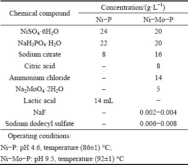
Table 1 Composition of Ni-P/Ni-Mo-P coatings�� plating baths and operating conditions
The residual stresses in the coatings were measured by a nanoindentation technique. The residual stresses were determined based on the calculation of the difference between the indentation contact areas of the stressed and stress-free samples proposed by WANG et al [17,18]. In order to produce stress-free samples, heat treatment at 800 ��C was conducted for each type of the coatings, based on the work reported by GUO et al [19] that the Ni-P coatings with different P contents after 800 ��C heat treatment were considered as microstrain- free samples. The nanoindentation tests were performed on the cross-sections and/or surfaces on the stressed and stress-free samples, respectively, using a nanoindentation equipped with a diamond Berkovich indenter. The cross sections of the samples were prepared by an EDM wire cutting machine (Agie Charmilles FI 440 ccS), using a brass wire with a diameter of 250 ��m. The samples were submerged in temperature-controlled deionized water throughout the cutting process. In this study, 48 different positions consisting of 6 (columns) �� 8 (rows) matrix were indented on the cross-section with 5 ��m interval, as shown in Fig. 1(a), to investigate the through-thickness stress distribution. In addition, 25 different positions consisting of 5 �� 5 matrix were indented with 10 ��m interval on the surface layer, as shown in Fig. 1(b), to calculate the residual stresses near the coating surfaces. The stressed and stress-free samples were indented to the same penetration depth of 200 nm to evaluate the residual stresses. The indentation profiles of the Berkovich indenter on the coating surface were measured using a DimensionTM 3100 atomic force microscope (AFM) and data fitting was performed by a Nanoscope analysis software.
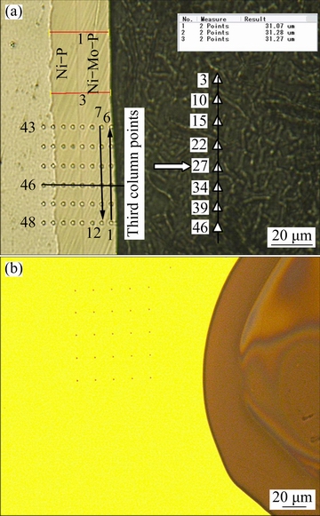
Fig. 1 Representative optical images of indentations on cross-section (a) and surface (b)
The morphologies, elemental composition and the crystal structures of the Ni-P/Ni-Mo-P coatings were examined using a Zeiss Ultra 55 scanning electron microscope (SEM) equipped with energy dispersive X-ray spectroscopy, a CAMECA SX100 electron probe microanalyser (EPMA) and a Philips XRD diffractometer with monochromatic Cu K�� radiation. EPMA measurements of 40 spots were carried out at 1 ��m interval to quantitatively obtain the elemental distribution on the cross-sections of the duplex coatings.
A Solartron Analytical ModuLab electrochemical test system was used to obtain the open-circuit potential (��OCP), linear sweep voltammograms (LSV) and polarisation curves (i.e. lg J�C�� curves) in a three- electrode mode at a sweeping rate of 1 mV/s. The coating was covered with Macdermid stop-off lacquer 45 to leave an exposed area of 0.5 cm2 as working electrode. Platinum rod and Ag/AgCl electrode were used as counter and reference electrodes, respectively. Prior to the measurement, the samples were immersed in 10% HCl solution for 30 min to establish steady open-circuit potential. Firstly, after reaching the steady ��OCP, the upper and lower potential limits of linear sweep voltammetry were set at ��10 mV with respect to the ��OCP. Secondly, the polarisation curves (lg J-��) were obtained after the above electrochemical measurements. The samples were kept in the solution for 5 min, and then the polarisation behaviour was recorded in a range of -600 to 800 mV (vs ��OCP). The corrosion potential (��corr) and corrosion current density (Jcorr) were deduced from the lg J-�� curves.
3 Results and discussion
3.1 Structural characteristics
The variations of chemical compositions along the depth on the cross section obtained by the EPMA measurement for the duplex Ni-P/Ni-Mo-P coatings, are shown in Fig. 2(a). The chemical compositions of the single Ni-P and Ni-Mo-P coatings were measured by EDS showing the single coatings as Ni-9.2P (mass fraction, %) and Ni-4.1Mo-6.5P (mass fraction, %), which were consistent with the average contents of each element measured by EPMA analysis. Figures 2(b) and (c) show the variations of P and Mo contents along the depth on the cross-section of the duplex coatings, respectively. It was found that there was a range of approximate 2 ��m between 15-17 ��m spots at the interface of the inner and outer layers which showed decreased contents of P and Mo down to 3.42% or 4.04%, respectively, in comparison with the average P or Mo content in the Ni-Mo-P coating. Therefore, this 2 ��m-thick layer was regarded as a transition layer between the inner and outer layers of the duplex coatings.
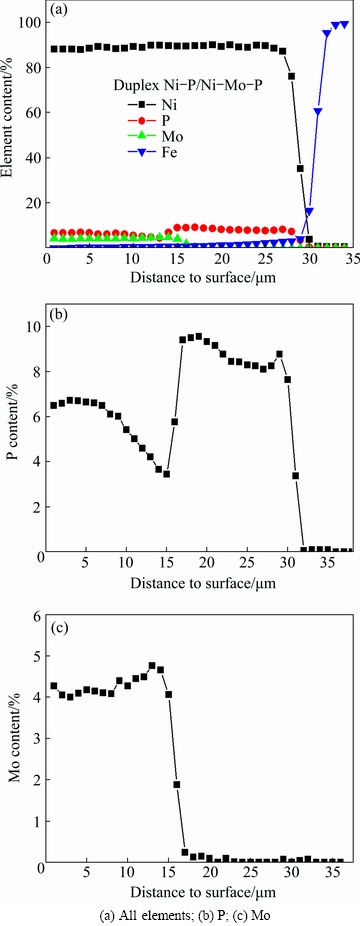
Fig. 2 Variations of chemical compositions measured by EPMA along cross-section of Ni-P/Ni-Mo-P duplex coatings
The XRD patterns of the as-plated Ni-P and Ni-Mo-P coatings are shown in Fig. 3. Only a single peak can be seen for both coatings, and the Ni (111) reflection of the Ni-P coating presents a broader peak than that of the Ni-Mo-P coating, suggesting that the Ni-P coating was amorphous, in a good agreement of the formation of amorphous phase for Ni-P alloy with a P content above 8% [20]. On the other hand, the Ni-Mo-P coating was likely to be a mixture of crystalline and amorphous, due to the incorporation of Mo in the Ni-P matrix enhancing the degree of crystallinity [3]. Similar result was also reported in Ref. [21], in which the incorporation of Mo from 1.1% to 14.9% in the Ni-P matrix caused the phase transformation from amorphous to crystalline structure.
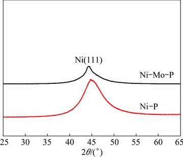
Fig. 3 XRD patterns of single Ni�CP and Ni-Mo-P coatings
The surface morphologies of the Ni-P/Ni-Mo-P coatings are shown in Fig. 4. It can be seen that both single Ni-P and Ni-Mo-P coatings presented a typical cauliflower structure. Some pores appeared at the nodule boundaries for the single Ni-P coating (Fig. 4(a)), but hardly appeared for the single Ni-Mo-P coating (Fig. 4(b)). The surface of the duplex coatings, by contrast, exhibited higher porosity but with less nodular structural morphology as shown in Fig. 4(c).
3.2 Residual stresses of Ni-P/Ni-Mo-P coatings
3.2.1 Residual stress characteristics of surface and cross-section
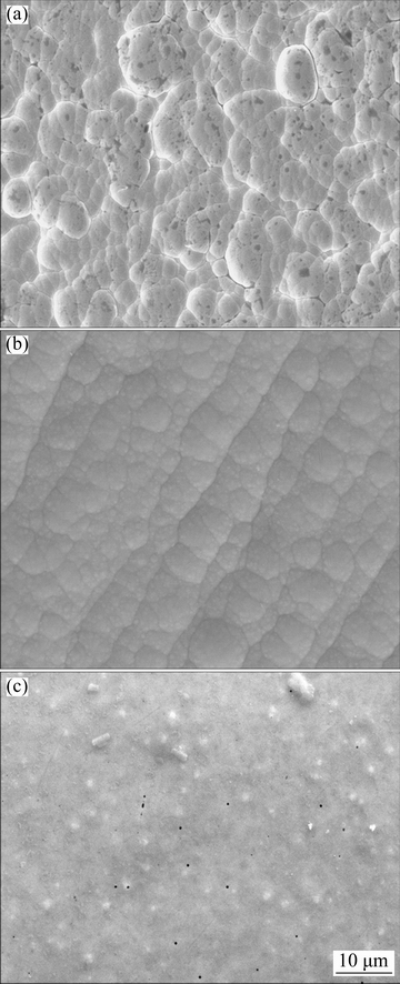
Fig. 4 Surface morphologies of as-plated single Ni-P (a), single Ni-Mo-P (b) and duplex Ni-P/Ni-Mo-P (c) coatings
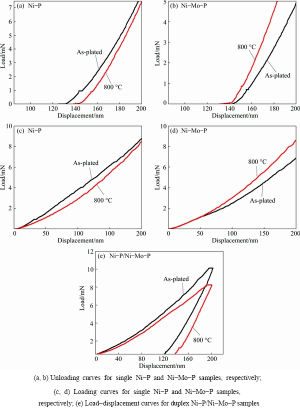
Fig. 5 Comparison of load-displacement curves for stress-free and stressed coatings at penetration depth of 200 nm
The nanoindentation measurements were carried out at a fixed penetration depth of 200 nm for the as-plated Ni-P/Ni-Mo-P coatings as well as the corresponding stress-free coatings after heat treatment at 800 ��C. Figure 5 shows the comparison of the load�Cdisplacement curves of the stressed and stress-free coatings. It is evident that the elastic recovery of indentation for the stressed and stress-free coatings after unloading was different. In order to explain such differences, the effects of residual stresses on elastic recovery of indentation was referred. It is claimed that a residual compressive stress could lead to the increase of the elastic recovery depth and the decrease of a residual depth [22]. On the contrary, a residual tensile stress could decrease the elastic recovery depth and increase a residual depth. As shown in Fig. 5(a), the residual depth in the as-plated Ni-P coating was less than that in the stress-free Ni-P coating. Based on the work in Ref. [22], it could be inferred that the as-plated Ni-P coating had a residual compressive stress. However, in Fig. 5(b), the residual depth in the as-plated Ni-Mo-P coating increased during unloading elastic recovery compared with its stress-free coating, therefore the residual stress in the as-plated Ni-Mo-P coating was tensile. Figures 5(c) and (d) show the loading curves of the Ni�CP and Ni-Mo-P coatings, respectively. It can be seen that the as-plated Ni-P coating required an increased force than its stress-free coating when indented to the same depth of 200 nm, confirming the existence of a residual compressive stress in the as-plated Ni-P coating. This is because a material with a compressive residual stress requires a larger force to be indented to the same depth as the one without residual stress [23]. However, the increase of the maximum shear stress under tensile stress might enhance indentation plasticity to produce a lower indentation load [24], the comparison of both curves from Fig. 5(d) also supported the finding of the presence of residual tensile stress in the as-plated Ni-Mo-P coating. Figure 5(e) shows the load-displacement curves of duplex Ni-P/Ni-Mo-P coatings. It was noted that in the case of the fixed same indentation depth of 200 nm, the indentation load needed for the as-plated Ni-P/Ni-Mo-P duplex coatings was higher than that of the stress-free duplex coatings, and resulted in larger elastic recovery depth during unloading. According to the above discussion, it could be deduced that the surface of the as-plated duplex coatings was in a state of compressive stress. It seemed that the stress state of the Ni-P inner layer somehow affected the stress state of the outer layer, i.e., the coating deposited on the surface with the compressive stresses remained the state of compressive stress. This needs to be further investigated.
In order to evaluate residual stresses on the cross sections of the duplex coatings, determination of a stress-free reference layer is crucial. ZHU et al [25] studied the residual stresses on the cross-section of the plasma-sprayed FeCrBSi coating, with the Ni/Al alloy as a transition layer, on the steel substrate. It was found that the residual stresses at the interface between the Ni/Al transition layer and the FeCrBSi coating were close to zero. Therefore, the interface was regarded as a stress- free layer. Based on the investigation by ZHU et al [25], it was assumed here that the stress-free layer on the cross-section of the duplex coatings should be the transition layer between the inner layer Ni-P and outer layer Ni-Mo-P. It is well known that phosphorus has a low solid solubility in nickel. When phosphorus content exceeds the solid solubility limit in nickel, a high degree of lattice disorder in a Ni-P alloy coating can be produced and consequently lattice strain can be formed. In general, the lower the P content, the smaller the lattice strain will be [26]. According to the EPMA results described earlier for the duplex coatings, the contents of both P and Mo in the transition layer were lower than those in the inner and outer layers, implying that the resultant lattice strains were small. Therefore, the assumption of the transition layer as stress-free reference should be reasonable. Figure 6(a) shows the load-displacement curves of the six indentations which were on the third column in Fig. 1(a) through-thickness distribution for the duplex Ni-P/Ni-Mo-P coatings. It was noted in Fig. 6(a) that under the fixed penetration depth, the load applied to the 22nd indentation of the third column, which is just located at the interface between the inner and outer layers (Fig. 1(a)), was higher than the other 5 indentations, which confirmed that the residual stress states on the cross-section of the inner and outer layers were all in tensile. This result was consistent with the work from Ref. [25] that the maximum load on the cross-section appeared in the stress-free position under the penetration depth of 170 nm. Figure 6(b) shows the unloading curves. It can be seen that the other 5 positions on the cross-section of inner and outer layers shifted to the right side with respect to the stress-free position, i.e., the generated elastic recoveries are smaller, indicating that residual stresses on the cross-section of the duplex coatings played an inhibition role for the elastic recoveries during unloading, which further confirmed that the residual stress on the cross-section was tensile.
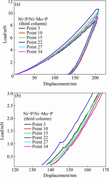
Fig. 6 Load-displacement curves along cross-section at penetration depth of 200 nm for Ni-P/Ni-Mo-P duplex coatings (a) and details showing movement of unloading curves (b)
3.2.2 Quantification of residual stresses in Ni-P/Ni-Mo- P coatings
Calculation of residual stresses by nanoindentation requires the knowledge of real contact area after unloading. The indentation response of a coating on substrate is determined by the elastic and plastic properties of both coating and substrate. The basic assumption of Oliver�CPharr method was that the contact periphery sunk in, without considering the influence of pile-up on contact area. However, BOLSHAKOV et al [27,28] used a finite element method and found that when the pile-up was small, the contact areas given by the Oliver�CPharr method matched very well with the true contact areas obtained from the finite element analyses; when the pile-up was significant, the Oliver�CPhar method underestimated the contact area by as much as 50%, resulting in errors in evaluation of residual stress properties. Therefore, the Oliver�CPharr method is only accurate for indentations with no significant pile-up or sink-in. ZHU et al [18] proposed another method to calculate real contact areas of pile-up materials. The residual stresses in the case of a fixed depth can be calculated based on the difference between the real contact areas of stressed and unstressed samples by analyzing the indentation load-depth data according to the following equations [29]:
For residual tensile stress,
 (1)
(1)
For residual compressive stress,
 (2)
(2)
where A and A0 are the projected contact areas with and without residual stress (����), respectively; H is the hardness of the Ni-P/Ni-Mo-P coatings, determined by the measurements of nanoindentation tests. The value of sin �� is a geometric factor, where �� is related to the indentation angle of the indenter. For a Berkovich indenter, ��=24.7�� and sin ��=0.418. In the present study, the residual stresses in the Ni-P/Ni-Mo-P coatings were determined using the calculation method by ZHU et al [18].
Figure 7 shows the AFM images of 2D and 3D indentations for the Ni-P/Ni-Mo-P coatings at the fixed depth of 200 nm. A significant pile-up was observed on the side of the indentation in Figs. 7(a)-(d). The light area around the edges of triangles was the piled-up material. OLIVER and PHARR [30] assumed that there was always some sink-in when a material was indented for several materials. Hence, the contact depth, hc, is always less than the total indenter displacement, hmax. However, when a material piles up, hc can be greater than hmax. The projected contact area for the piled-up material should contain the ��extra�� area formed around the edges of the indentation. It can be seen from the AFM images of the indentations in Fig. 7 that the piled-up material formed an arc only along the sides of the triangle but not at the corners. This is consistent with the assumption of the ��true�� contact area equation, proposed by ZHU et al [18].
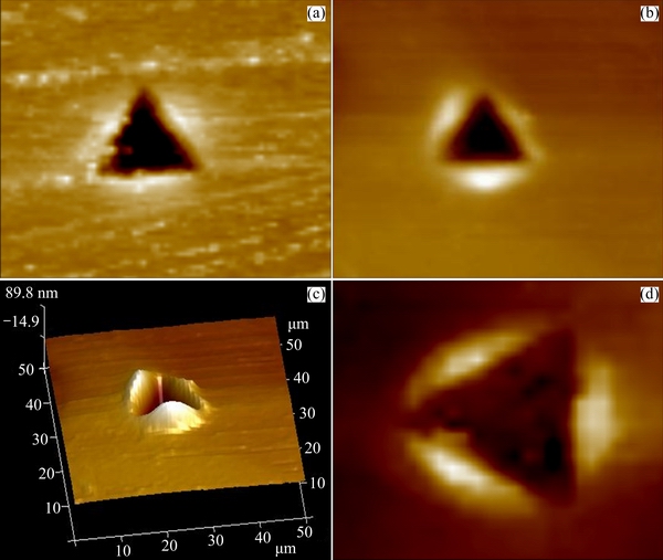
Fig. 7 Typical AFM images of 2D and 3D indentation morphologies for as-plated Ni-P coating (surface) (a), as-plated Ni-Mo-P coating (surface) (b), duplex Ni-P/Ni-Mo-P coatings annealed at 800 ��C (surface) (c) and as-plated Ni-P/Ni-Mo-P duplex coatings (cross-section) (d)
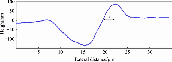
Fig. 8 Cross-sectional profile of indentation at fixed depth of 200 nm for duplex coatings annealed at 800 ��C
 (3)
(3)
where �� can be determined using the following derived formula in Ref. [18]:
 (4)
(4)
where the projected pile-up height (x), the average pile-up height ( ) around the three sides of an indentation and the maximum depth (hmax) can be obtained from cross-section profile and load- displacement curves of an indentation. In the present study, the cross-section profile of an indentation was acquired using AFM with Nanoscope Analysis software. Figure 8 shows the cross-section profile of the duplex coating annealed at 800 ��C. Based on the calculation method by ZHU et al [18] for the real contact area of the pile-up material and the hardness value measured by the nanoindentation as well as Eqs. (1) and (2), the residual stresses for the coatings were determined. For the single as-plated Ni-P and Ni-Mo-P coatings as well as duplex Ni-P/Ni-Mo-P coatings, the values were 241, 257 and 206 MPa, respectively. Compared with other work [31] the residual stress of the electroless plated Ni-8.7P coating deposited over Al films on Si substrate was calculated using the Stoney��s equation, the value was 220 MPa in tensile state, the values calculated in our work were reasonable.
3.3 Corrosion resistance of Ni-P/Ni-Mo-P coatings
The corrosion processes of Ni-P/Ni-Mo-P coatings in HCl solution involve two forms of corrosion, uniform corrosion and pitting corrosion. The uniform corrosion is caused by dissolving Ni in the presence of H+ in HCl solution [32]. The pitting corrosion is the result of preferential adsorption of Cl- on the weak sites of the coating surface. The weak sites refer to nodular boundaries and porosity [33].
In this work, the corrosion resistance of the Ni-P/Ni-Mo-P coatings in 10% HCl solution was investigated by linear sweep voltammetry (Fig. 9) and potentiodynamic polarisation (Fig. 10) as well as morphological observation by SEM after the polarisation tests (Fig. 11).
Figure 9 shows typical LSV curves for the Ni-P/Ni-Mo-P coatings measured at the vicinity of the ��OCP. Linear polarisation resistance (Rp) can be calculated using the following equation:
 (5)
(5)
where ���� is the polarisation potential and ��J is the polarisation current density. The values of Rp calculated from the curves in Fig. 9 are listed in Table 2.
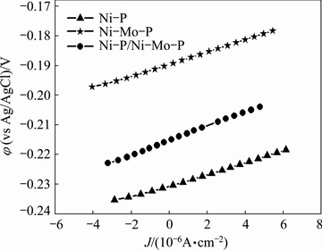
Fig. 9 LSV curves measured in 10% HCl solution at vicinity of open-circuit potential for Ni-P/Ni-Mo-P coatings
Table 2 Potentiodynamic polarisation data of Ni-P/Ni-Mo-P coatings in 10% HCl solution
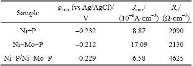
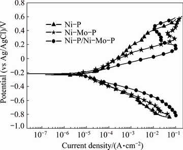
Fig. 10 Polarisation curves measured in 10% HCl solution from -600 to 800 mV (vs ��OCP) for Ni-P/Ni-Mo-P coatings
3.3.1 Comparison of single Ni-P coating and single Ni-Mo-P coating
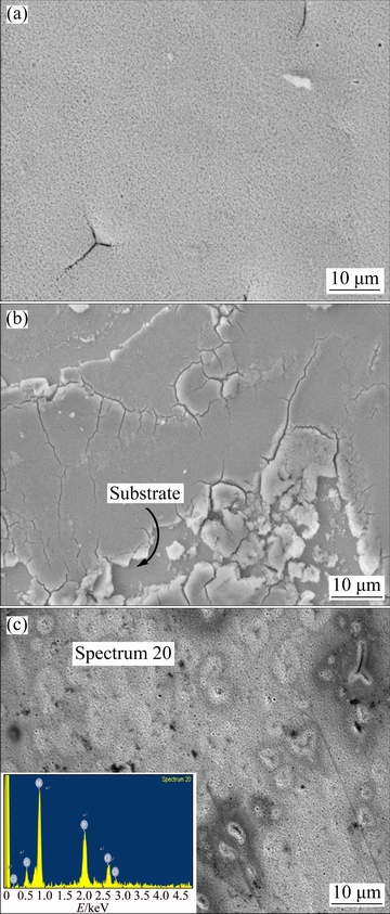
Fig. 11 SEM images of single Ni-P coating (a), single Ni-Mo-P coating (b) and duplex Ni-P/Ni-Mo-P coatings with EDS spectrum (c) after polarisation tests in 10% HCl solution
Generally, increasing P content in Ni-P based alloy increases in corrosion resistance with higher polarisation resistance [34]. In this work, the single Ni-Mo-P coating with a lower P content of 6.5% presented a slightly higher Rp of 2130 ��/cm2 compared with the Rp of 2090 ��/cm2 for the single Ni-P coating with a higher P content of 9.1%. The result may suggest that the contribution of codeposition of Mo into Ni-P coating to the increase in Rp was more significant than that of increasing the P content. This may be related to the addition of Mo increases the pitting potential of Ni-P coatings. Figure 10 shows the polarisation curves for the Ni-P/Ni-Mo-P coatings recorded from -600 to 800 mV (vs ��OCP). The electrochemical parameters including corrosion potential and corrosion current density for the coatings are summarised in Table 2. In principle, the increase in the polarisation resistance implied the decrease in the corrosion current density. However, the single Ni�CP coating had a lower corrosion current density of 8.87��10�C6 A/cm2 than the single Ni-Mo-P coating of 17.09��10�C6 A/cm2. The corrosion morphological observation of the coating surfaces by SEM, as shown in Figs. 11(a) and (b), revealed a significant difference, in which the single Ni-P coating remained the integrity of the coating after the polarisation, but the single Ni-Mo-P coating was partially spalled off exposing the steel substrate. To explain the difference, the residual stresses must be considered. As described earlier, the residual stress for the single Ni-P coating was compressive, while it was tensile for the single Ni-Mo-P coating. The presence of tensile stress may have a detrimental effect on localised corrosion by promoting the growth of the pits that were initiated by adsorption of the Cl- at the nodular boundaries and developing corrosion-initiated cracking. As a result, it led to partial spallation of the coating as observed for the single Ni-Mo-P coating. On the contrary, the presence of compressive stress might be capable of suppressing the growth of the pre-existing pores and impeding the development of cracks from the pre-existing pores in the coating and blocking the pathway of corrosive agents. Therefore, it was believed that the corrosion process of the single Ni-P coating with residual compressive stress was dominated by uniform corrosion with retaining the integrity of the coating; the corrosion process of the single Ni-Mo-P coating with tensile stress was mainly controlled by pitting corrosion, and corrosion-initiated cracking. In addition, it was worth considering a possible influence from the phases. As described earlier, the single Ni-P coating consisted of amorphous phase, but the single Ni-Mo-P coating consisted of amorphous Ni-Mo-P and nano-crystalline Ni-Mo zones [21]. Therefore, it might be deduced that the amorphous nature, with the absence of grain boundaries, dislocations, kink sites and other surface defects, in the Ni-P coating was beneficial to corrosion resistance.
3.3.2 Comparison of single Ni-Mo-P coating with duplex Ni-P/Ni-Mo-P coatings
Compared with the single Ni-Mo-P coating, the duplex Ni-P/Ni-Mo-P coatings exhibited a higher polarisation resistance (4625 ��/cm2) and a lower corrosion current density (6.58��10�C6 A/cm2), suggesting better resistance to corrosion. However, detailed corrosion processes observed from the polarisation curves in Fig. 10 appeared rather complicated involving both uniform and pitting corrosion processes as well as the effect of the hypophosphite layer. Although the duplex Ni-P/Ni-Mo-P coatings had less nodular structure than the single Ni-Mo-P coating with a nodular structure, the duplex coatings had much higher porosity as shown in Figs. 4(b) and (c). Such pre-existing porosity in the coating provided preferential sites for Cl�C adsorption which led to more severe pitting corrosion. Therefore, the current densities on the anodic branch for the duplex coatings were higher than those for the single Ni-Mo-P coating which had much less or no porosity observed. However, as observed in Figs. 11(b) and (c), after polarisation, the duplex coatings remained integrity, but the single Ni-Mo-P coating was partially spalled off. This can be explained by the residual stresses. As described earlier, the duplex Ni-P/Ni-Mo-P coatings had a compressive stress and the single Ni-Mo-P had a tensile stress. Although the pre-existing porosity in the duplex coatings resulted in higher degree of pitting corrosion, the presence of the compressive stress impeded the corrosion propagation and prevented the formation of corrosion-cracking around the pits. Therefore, the coating remained integrity. For the single Ni-Mo-P coating, the adsorption of Cl�C on the nodular boundaries resulted in the formation of pitting corrosion and, due to the presence of tensile stress, the corrosion cracking around the pits could be rapidly expanded, leading to spallation of the coating.
In addition, from the polarisation curves in Fig. 10, it was noticed that in the anodic polarisation region of the duplex Ni-P/Ni-Mo-P coatings, i.e., between potentials of 0.23 and 0.43 V, a passivation phenomenon with a passive current density of about 0.015 A/cm2 was observed and the passivation potential range reaches 200 mV. The passivation behaviour was believed to be related to the formation of hypophosphite layer on the coating surface. The EDS analysis (Fig. 11(c)) on the duplex coatings surface after polarisation showed an increased content of P to 12.7% and no detection of Mo, indicating that the corrosion had completely removed the Ni-Mo-P outer layer by comparing with the original Ni-4.1Mo-6.5P coating. Therefore, under this condition, it was possible to form a hypophosphite layer which was protective. This was also reported in Ref. [31]. On the other hand, the presence of the residual compressive stress may also contribute to the compactness and completeness of the layer, preventing the hydration of nickel leading to the passivation.
For the single Ni-Mo-P coating, although it was also possible for the formation of hypophosphite layer, the presence of tensile stress on the coating may have detrimental effect on its completeness, which had much less passivation as observed in Fig.10.
4 Conclusions
1) The single Ni-P coating and the duplex Ni-P/Ni-Mo-P coatings exhibited the residual compressive stresses of 241 and 206 MPa respectively, while the single Ni-Mo-P coating exhibited the residual tensile stress of 257 MPa.
2) The stress states affect the corrosion form of coatings. The corrosion process of the single Ni-P coating was dominated by uniform corrosion due to the presence of compressive stress, while the corrosion process of the single Ni-Mo-P coating was mainly in the form of pitting, which was adversely affected by the tensile stress.
3) The duplex Ni-P/Ni-Mo-P coatings showed better corrosion resistance than their respective single coating. The presence of the compressive stress on the duplex Ni-P/Ni-Mo-P coatings prevented the expansion of corrosion-cracking around the pits, and promoted the compactness and completeness of the hypophosphite layer which acted as passive protection at high potential range during anodic polarisation.
Acknowledgments
The authors are grateful for the use of analytical facilities in The University of Manchester.
References
[1] LIU W L, HSIEH S H, CHEN W J. Growth behaviour of electroless Ni-Co-P deposits on Fe [J]. Applied Surface Science, 2009, 255: 3880-3883.
[2] LI Song-mei, HAN Yu, LIU Jian-hua, YU Mei. Process research on electroless Ni-Fe-P deposition with high depositing speed [J]. Materials Engineering, 2010, 8: 44-50. (in Chinese)
[3] BALARAJU J N, RAMAN N, MANIKANDANATH N T. Nanocrystalline electroless nickel poly-alloy deposition: Incorporation of W and Mo [J]. Transactions of the IMF, 2014, 92: 169-176.
[4] SELVI V E, CHATTERJI P, SUBRAMANIAN S. Autocatalytic duplex Ni-P/Ni-W-P coatings on AZ31B magnesium alloy [J]. Surface and Coatings Technology, 2014, 240: 103-109.
[5] LIU Hong, GUO Rong-xin, BIAN Jian-sheng. Effect of laser- induced nanocrystallisation on the properties of electroless Ni-P/Ni-W-P duplex coatings [J]. Crystal Research and Technology, 2013, 48: 100-109.
[6] ZHANG W X, JIANG Z H, LI G Y. Electroless Ni-P/Ni-B duplex coatings for improving the hardness and the corrosion resistance of AZ91D magnesium alloy [J]. Applied Surface Science, 2008, 254: 4949-4955.
[7] SHA Wei, WU X, KEONG K G. Electroless copper and nickel�C phosphorus plating: Processing, characterisation and modelling [M]. Cambridge: Woodhead Publishing, 2011.
[8] KATTAMIS T Z, CHEN M, SKOLIANOS S. Effect of residual stresses on the strength, adhesion and wear resistance of SiC coatings obtained by plasma-enhanced chemical vapour deposition on low alloy steel [J]. Surface and Coatings Technology, 1994, 70: 43-48.
[9] TAYLOR C A, WAYNE M F, CHIU W K S. Residual stress measurement in thin carbon films by Raman spectroscopy and nanoindentation [J]. Thin Solid Films, 2003, 429: 190-200.
[10] LEE Y H, TAKASHIMA K, KWON D. Micromechanical analysis on residual stress-induced nanoindentation depth shifts in DLC films [J]. Scripta Materialia, 2004, 50: 1193-1198.
[11] MOON M W, JENSEN H M, HUTCHINSON J W. The characterization of telephone cord buckling of compressed thin films on substrates [J]. Journal of the Mechanics and Physics of Solids, 2002, 50: 2355-2377.
[12] WANG Y, LI K Y, SCENINI F, JIAO J, QU S J, LUO Q, SHEN J. The effect of residual stress on the electrochemical corrosion behaviour of Fe-based amorphous coatings in chloride-containing solutions [J]. Surface Coatings Technology, 2016, 302: 27-38.
[13] WEIL R, PARKER K. The properties of electroless nickel [M]. New York, 1990.
[14] ALANAZI N M, EL-SHERIK A M, ALAMAR S H, SHEN S. Influence of residual stresses on corrosion and wear behaviour of electrodeposited nanocrystalline cobalt-phosphorus coatings [J]. International Journal of Electrochemical Science, 2013, 8: 10350-10358.
[15] RASHTCHI H, RAEISSI K, SHAMANIAN M, ACEVEDO GOMEZ Y, LAGERGREN C, WRELAND LINDSTROM R, RAJAEI V. Evaluation of Ni-Mo and Ni-Mo-P electroplated coatings on stainless steel for PEM fuel cells bipolar plates [J]. Fuel Cells, 2016, 16: 784-800.
[16] LIU Hong, GUO Rong-xin, ZONG Yun, HE Bing-qing, LIU Zhu. Comparative study of microstructure and corrosion resistance of electroless Ni-W-P coatings treated by laser and furnace-annealing [J]. Transactions of Nonferrous Metals Society of China, 2010, 20: 1024-1031.
[17] WANG Hai-dou, ZHU Li-na, XU Bin-shi. Measurement of residual stress of plasma sprayed Fe-based coating by nanoindentation [J]. Journal of Mechanical Engineering, 2013, 49: 1-4. (in Chinese)
[18] ZHU Li-na, XU Bin-shi, WANG Hai-dou. Determination of hardness of plasma-sprayed FeCrBSi coating on steel substrate by nanoindentation [J]. Materials Science and Engineering A, 2010, 528: 425-428.
[19] GUO Z, KEONG K G, SHA W. Crystallisation and phase transformation behaviour of electroless nickel phosphorus platings during continuous heating [J]. Journal of Alloys and Compounds, 2003, 358: 112-119.
[20] KEONG K G, SHA W. Crystallisation and phase transformation behaviour of electroless nickel�Cphosphorus deposits and their engineering properties [J]. Surface Engineering, 2002, 18: 329-343.
[21] KOIWA I, USUDA M, YAMADA K. Effect of heat-treatment on properties of electroless-deposited nickel-molybdenum-phosphorus alloy films [J]. Journal of Electrochemical Society: Solid�CState Science and Technology, 1988, 135: 718-726.
[22] XU Z H, LI X. Estimation of residual stresses from elastic recovery of nanoindentation [J]. Philosophical Magazine, 2006, 86: 2835-2846.
[23] WANG Q, OZAKI K, ISHIKAWA H. Indentation method to measure the residual stress induced by ion implantation [J]. Nuclear Instruments and Methods In physics Research Section B, 2006, 242: 88-92.
[24] LEE Y H, KWON D. Estimation of biaxial surface stress by instrumented indentation with sharp indenters [J]. Acta Materialia, 2004, 52: 1555-1563.
[25] ZHU Li-na, XU Bin-shi, WANG Hai-dou. On the evaluation of residual stress and mechanical properties of FeCrBSi coatings by nanoindentation [J]. Materials Science and Engineering A, 2012, 536: 98-102.
[26] LIU Hong, GUO Rong-xin, ZONG Yun, HE Bing-qing. Evolution of grain size and microstrain of electroless deposited Ni-W-P coatings with high phosphorus content during heat treatment [J]. Transactions of Materials and Heat Treatment, 2010, 31: 123-128. (in Chinese)
[27] BOLSHAKOV A, OLIVER W C, PHARR G M. Influences of stress on the measurement of mechanical properties using nanoindentation: Part II. Finite element simulations [J]. Journal of Materials Research, 1996, 11: 760-768.
[28] BOLSHAKOV A, PHARR G M. Influences of pile up on the measurement of mechanical properties by load and depth sensing indentation techniques [J]. Journal of Materials Research, 1998, 13: 1049-1058.
[29] SURESH S, GIANNAKOPOULOS A E. A new method for estimating residual stresses by instrumented sharp indentation [J]. Acta Materialia, 1998, 46: 5755-5767.
[30] OLIVER W C, PHARR G M. An improved technique for determining hardness and elastic modulus using load and displacement sensing indentation experiments [J]. Journal of Materials Research, 1992, 7: 1564-1583.
[31] SONG J Y, YU J. Residual stress measurements in electroless plated Ni-P films [J]. Thin Solid Films, 2002, 415: 167-172.
[32] ZENG Z O, ZHOU T. Mechanisms of anodic dissolution and passivation of nickel [J]. Journal of Central South Mining Institute, 1987, 18: 338-354. (in Chinese)
[33] SONG Y W, SHAN D Y, HAN E H. High corrosion resistance of electroless composite plating coatings on AZ91D magnesium alloys [J]. Electrochimica Acta, 2008, 53: 2135-2143.
[34] BAI A, CHUANG P Y, HU C C. The corrosion behaviour of Ni-P deposits with high phosphorous contents in brine media [J]. Materials Chemistry and Physics, 2003, 82: 93-100.
�� ��1��Ǯ����2
1. ��³��ҵ��ѧ(ɽ��ʡ��ѧԺ) ��е����������ѧԺ������ 250353��
2. Corrosion and Protection Centre, School of Materials, The University of Manchester, Manchester, M13 9PL, UK
ժ Ҫ��ͨ����ѧ�������Ʊ�Ni-P��Ni-Mo-P ���Ʋ��Լ�����ɷ���ͬ��Ni-P/Ni-Mo-P˫�Ʋ㡣��������ѹ�۷���AFM���������Ʋ����ͽ���IJ���Ӧ�������õ绯ѧ�������Ʋ���10% HCl��Һ�еĸ�ʴ��Ϊ���Ի�öƲ����Ӧ���븯ʴ��Ϊ֮��Ĺ�ϵ����������� Ni-P���Ʋ��Ni-P/Ni-Mo-P˫�Ʋ����Ϊ����ѹӦ�����ֱ�Ϊ241�� 206 MPa��Ni-Mo-P���Ʋ���ֳ�257 MPa�IJ�����Ӧ��������ѹӦ����ֹ�Ʋ��п��������������Ʋ�������ԡ�Ni-P/Ni-Mo-P˫�Ʋ�����ǵĵ��Ʋ���и��õ���ʴ�ԡ����⣬�Ʋ��Ӧ��״̬Ӱ���丯ʴ��ʽ��
�ؼ��ʣ���ѧ������Ni-P/Ni-Mo-P˫�Ʋ㣻����Ӧ��������ѹ�۷�����ʴ��
(Edited by Xiang-qun LI)
Foundation item: Project (ZR2011EMM014) supported by Shandong Provincial Natural Science Foundation of China
Corresponding author: Hong LIU; Tel: +86-13953159215; E-mail: newhsx@163.com
DOI: 10.1016/S1003-6326(18)64896-4

