
Effect of Y2O3 on microstructure and oxidation of chromizing coating
ZHOU Yue-bo(���²�), ZHANG Hai-jun(�ź���), WANG Yong-dong(������)
College of Materials Science and Engineering, Heilongjiang Institute of Science and Technology,
Harbin 150027, China
Received 28 November 2007; accepted 3 March 2008
Abstract: A Y2O3-modified chromizing coating was produced by chromizing an as-electrodeposited Ni-Y2O3 composite film using pack cementation method at 1 100 �� for 3 h. For comparison, chromizing was also performed under the same condition on an as- deposited Ni film without Y2O3 particles. Oxidation at 900 �� for 120 h indicates that although on both two chromizing coatings chromia scales grow during oxidation, the Y2O3-modified chromizing coating exhibits an increased oxidation resistance due to the formation of thinner, denser and finer-grain scale. The effect of Y2O3 on the coating formation and the coating oxidation behavior was discussed in detail.
Key words: Y2O3; electrodeposition; chromizing; oxidation; reactive element effect
1 Introduction
The addition of small amount of certain reactive elements or their oxides which have a high affinity for oxygen, such as Y, Ce, La, can improve the oxidation resistance of certain high-temperature alloys or coatings. The phenomenon was first reported in 1937[1] and is referred to as reactive element effect(REE). Oxidation of alloys or coatings with addition of RE or RE oxides has been widely reported[2-4]. As for the chromia-formers, the decrease of the oxidation rate has been ascribed to an inversion of chromia growth mechanisms from predominant outward cation diffusion in the absence of RE into dominant inward oxygen diffusion. This inversion caused a change of the oxide scale structure from large columnar chromia grains to a small grain structure on reactive element-doped samples[4-5]. RE or RE oxides are commonly added into alloys or coatings by different techniques, such as alloying[3], implantation [4] and sol-gel deposition[6].
Chromizing coating, traditionally manufactured by pack cementation, has been normally used as protective coating to increase high temperature oxidation, corrosion and wear resistance of metals[7-8]. Recently, PENG et al[9-10] added CeO2 particles into chromium coatings by chromizing the codeposited Ni-CeO2 nanocomposite coatings using pack cementation method at 1 120 ��. The oxidation results in air[9] and simulated coal- combustion gases[10] showed that the chromizing coatings with CeO2 particles exhibited better oxidation resistance compared with CeO2-free chromizing coatings. ZHANG et al[11] and ZHOU et al[12] also found that CeO2 and Y2O3 significantly improved the oxidation resistance of the chromizing coating at temperatures below 800 ��. In this work, by considering the beneficial effect of Y2O3 on the coating formation and oxidation, a Y2O3-modified chromizing coating was produced at 1 100 �� using similar pack cementation method, and its oxidation performance was reported. For comparison, preparation and oxidation of chromium coatings on the Ni film were also carried out under the same condition.
2 Experimental
Samples with dimensions of 15 mm��10 mm��2 mm were cut from an electrolytic nickel plate. They were ground to a final 800# SiC paper. After being ultrasonically cleaned in acetone, they were electrodeposited with a 60 mm-thick film of Ni-Y2O3 composite from a nickel sulfate bath containing certain content of Y2O3 microparticles with an average particle size of 2.5 mm. The current density used was 3 A/dm2, the bath temperature was 35 ��, and the pH was 5.6-6.2. For comparison, a 60 mm-thick Ni film was also electroplated on Ni using the same bath and the same deposition parameters but without adding Y2O3 particles. Before the electrodeposition, the samples were degreased in alkaline solution, dipped in acid (10%HCl) and finally washed with distilled water. During the electrodeposition, the electrolyte was magnetically stirred in order to keep the particles dispersed and suspended. EDAX results showed that the as-deposited composite film contained around 7%-10% Y2O3(mass fraction). Chromizing on the samples coated with Ni-Y2O3 composite and nickel film was carried out using pack cementation at 1 100 �� for 3 h in a powder mixture of 50Cr (particle size: 75 mm)+47Al2O3 (particle size: 75 mm)+3NH4Cl (mass fraction, %) in a pure Ar atmosphere. Then the chromized samples were brushed, cleaned in bubbling distilled water for 30 min and finally ultrasonically cleaned in acetone to remove any loosely embedded pack particles. Oxidation was conducted in a muffle furnace at 900 �� for 120 h and the mass measurement was conducted after fixed time intervals using a balance with 0.01 mg sensitivity. The microstructure of the various chromized coatings before and after oxidation was investigated using transmission electron microscopy(TEM), scanning electron microscopy(SEM) with energy dispersive X-ray analysis (EDAX) and X-ray diffractometry(XRD).
3 Results
3.1 Microstructure
A regular pyramidal structure is observed on the surface of the as-deposited nickel film[13]. However, with the additions of Y2O3 particles, the grain size is reduced and the morphology is changed to spherical crystal, as shown in Fig.1. EDAX analysis result shows that the white particles have higher Y2O3 content, suggesting they are the fresh deposited Y2O3 particles. Although the distribution of micrometer-size Y2O3 particles can be observed in some locations, the particles do not present in most areas.
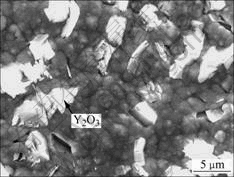
Fig.1 Surface morphology of as-deposited Ni-Y2O3 composite
TEM investigation[12] reveals that Ni-Y2O3 composite generally comprises Ni grains with size of 10-150 nm, which is larger than the Ni grains of Y2O3-free Ni film with size of 15-60 nm. Numerous twins formed in both films. No defects such as pores and cracks are seen.
Fig.2 shows the surface and cross-sectional micrographs of chromizing coatings on Ni film and Ni- Y2O3 composite. The chromized layers are both about 45 mm in thickness and exhibit a double-layer structure. It can be seen that the outer layer (area 1 in Fig.2(d)) for Y2O3-dispersed coating is thicker than that formed in Y2O3-free samples (area 1 in Fig.2(b)). From Fig.2, it is clear that the Y2O3-dispersed chromium coating exhibits a finer-grain structure, suggesting that Y2O3 particles dispersed in the electrodeposited Ni film retard the grain growth. The grain refinement enhances the diffusion of chromium during pack cementation, leading to higher Cr content of the Y2O3-dispersed chromizing coating than that of the Y2O3-free samples at a given distance from the coating surface, as shown in Fig.3.
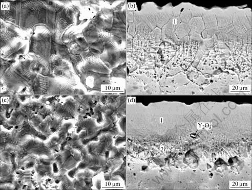
Fig.2 Surface (a, c) and cross-sectional (b, d) micrographs of chromizing coatings on Ni film (a, b) and Ni-Y2O3 composite (c, d)
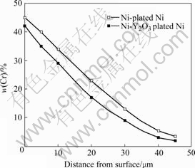
Fig.3 Chromium concentration profiles for chromizing coatings on various substrates
3.2 Oxidation performance
The oxidation kinetics for the two chromizing coatings at 900 �� for 120 h in air is shown in Fig.4. At 900 ��, the kinetics for the Y2O3-dispersed and Y2O3-free chromizing coatings obeys the parabolic rate law to a good approximation. The corresponding oxidation parabolic constant calculated for each curve is shown in Fig.4. It is obvious that the Y2O3-dispersed chromizing coating exhibits better oxidation resistance than the Y2O3-free chromizing coatings.
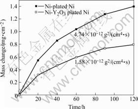
Fig.4 Oxidation kinetics of various chromizing coatings at 900 �� for 120 h
3.3 Microstructures of oxide scales
Fig.5 shows the SEM top-views of the scales formed on two chromizing coatings after 20 h exposure at 900 ��. On the basis of the EDAX analysis, chromia scales exclusively form on the two chromizing coatings. Compared with the chromizing coating on Ni-plated sample, the chromia scales formed on the Y2O3-dispersed chromizing coatings have finer grains.
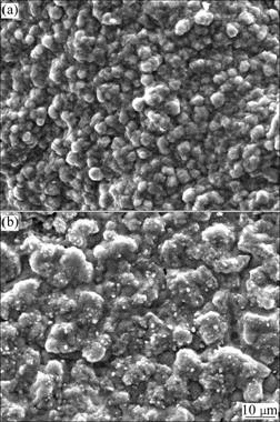
Fig.5 Surface morphologies of chromia scales formed on chromizing coatings of Ni film (a) and Ni-Y2O3 composite (b) at 900 �� for 20 h
The XRD analysis indicates that the oxide scales formed on the both coatings after exposure at 900 �� for 120 h are single phase Cr2O3, as shown in Fig.6. For oxidation of the Y2O3-dispersed coating, a higher intensity peak from the coating substrate appears (see Fig.6(b)), suggesting that the chromia scale formed is thinner in this case. In contrast, the chromia formed in the Ni-plated sample exhibits a preferential growth on the (202) plane (see Fig.6(a)).
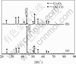
Fig.6 XRD patterns of oxide scale on various chromium coatings after 120 h oxidation in air at 900 ��: (a) Ni-Y2O3 composite film; (b) Ni film
By comparing the corresponding cross-sectional SEM images of the chromia scale on both chromizing coatings after exposure in air at 900 �� for different time in Fig.7, it can be seen that the oxide scale thickness formed on the chromizing coating is significantly reduced due to the addition of Y2O3 particles. The results suggest that the Y2O3-dispersed chromizing coating exhibits better oxidation resistance than the Y2O3-free chromizing coating, which is consistent with the oxidation kinetics in Fig.4.
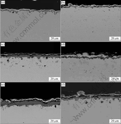
Fig.7 Cross-sectional SEM images of chromia scales formed on chromizing coatings of Ni film (a, c, e) and Ni-Y2O3 composite (b, d, f) at 900 ��: (a, b) 20 h; (c, d) 60 h; (e, f)120 h
The fracture cross-sectional micrographs of the two chromizing coatings after exposure at 9 00 �� for 120 h are shown in Fig.8. For Y2O3-free chromizing coating, the chromia scale is composed of larger columnar grains with the width increasing from the interface to surface. However, for the Y2O3-dispersed chromizing coating, the chromia scale is composed of a small equiaxed grain.
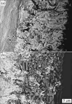
Fig.8 Fracture cross-sectional images of various chromizing coatings on Ni film (a) and Ni-Y2O3 composite (b) at 900 �� for 120 h
4 Discussion
Fig.2 shows that two chromizing coatings are double-layered. The outer layers are formed from the contribution of the outward growth, and the inner layers are formed from the contribution of the inward growth. The chromizing coating on the Ni film exhibits a very thin outer layer, implying that the chromizing processing is dominated by inward chromium diffusion. The forma- tion of the thicker outer layer for Y2O3-dispersed chromi- chromizing coating compared with Y2O3-free chromizing coating may be attributed to the Y2O3 particles in the electrodeposited composite acting as a diffusion barrier to block the inward chromium diffusion[9-11]. At the same time, the Y2O3 particles dispersed in the electrodeposited Ni coating serve as source for producing Y ions. Driven by the difference of oxygen potential, the Y ions transport outward and incorporate into the growing chromizing coating[14]. Afterwards, they will segregate to the grain boundary. The segregation retards the grain growth of the chromizing coating, which leads to a finer-grain structure[9-12].
Compared with oxidation of the chromium coating on the Ni-plated sample, the one on the Ni-Y2O3 coated sample exhibits an apparently low scaling rate (Fig.3). Many investigations show that for Y2O3, the following effects are generally accepted[15-16]: 1) promoting the selective oxidation of chromium by providing nucleation sites for Cr2O3 during initial exposure; 2) reducing scaling rate by changing the scaling mechanism from dominant outward chromium diffusion in the absence of RE into dominant inward oxygen diffusion.
Fig.2 suggests that Y2O3 particles dispersed in the electrodeposited Ni film leads to the formation of a fine-grain chromium-coating structure, which enhances the diffusion of chromium to the oxidation front and consequently accelerates the healing of the chromia layer in a shorter time compared with the oxidation of the coating in the absence of Y2O3[9-12]. This is the reason why the oxidation rate of the Y2O3-dispered chromium coating is lower than that of the coating on the Ni-plating during the early stage of oxidation. After the formation of continuous chromia scale, the finer-grain scale formed on the Y2O3-dispered chromium coating (Fig.4 and Fig.5) should grow even faster than that formed on the Y2O3-free chromium coating due to an increase in the number of grain boundaries per unit volume. However, the fact that a significant scalling rate reduction occurs, suggesting that grain-boundary diffusion of Cr cations is hindered to a great extent. The reason may be that the chromia scale is incorporated by Y ions released from the dispersed Y2O3 particles when they are incorporated into the growing scale[14]. Once being incorporated into the growing scale, they would potentially improve the oxidation resistance through blocking the dominant grain boundary outward diffusion of chromium. At the same time, a modification of the oxide scale structure from large columnar chromia grains to a small grain structure occurs, as seen in Fig.8.
From above analysis, the lower oxidation rate of Y2O3-dispersed chromizing coating is associated with the effect of Y2O3, which can be summarized as follows. First, Y2O3 co-deposited in the electrodeposited Ni matrix leads to the formation of a fine-grain chromium- coating structure, which enhances the diffusion of chromium to the oxidation front and consequently accelerates the formation of chromia layer in a shorter time[9-12]. Second, the Y2O3 dispersion may release Y ion that enters the growing chromia scale[14] and segregates to the scale grain boundaries. In this case, the dominant diffusion of chromium cations during the growth of chromia scale is blocked, leading to a decrease of oxidation[9-12, 17]. At the same time, pinning[18] and ��solute�Cdrag�� effect[19] of the dispersion particles at oxide grain boundaries will also contribute to a finer- grain oxide in the Y2O3-modified chromizing coatings.
5 Conclusions
1) By chromizing an as-electrodeposited Ni-Y2O3 composite coating, Y2O3-dispersed chromizing coatings were manufactured. The chromizing coatings formed on the Ni-Y2O3 composite film are finer than those on the Ni film due to the fact that Y2O3 particle retards the grain growth during the chromizing.
2) The Y2O3-modified chromizing coating exhibits a superior oxidation resistance due to the formation of thinner and finer-grained chromia scale. The effects of Y2O3 on the oxidation of the chromized coatings include the following aspects. Y2O3 can retard the grain growth of the chromizing coating, which enhances Cr diffusion to the oxidation front and consequently accelerates the formation of a continuous chromia scale. Y ions from the Y2O3-dispersed coating incorporating into the growing scale and segregating to the chromia grain boundaries change the oxidation mechanism from outward chromium diffusion in the absence of RE into dominant inward oxygen diffusion.
References
[1] PFEIL L B. Improvement in heat-resisting alloys. UK 459848 [P]. 1937.
[2] MOON D P. Role of reactive elements in alloy protection [J]. Mater Sci Tech, 1989, 5: 754-763.
[3] CUEFF R, BUSCAIL H, CAUDRON E, ISSARTEL C, RIFFARD F. Oxidation behaviour of Kanthal A1 and Kanthal AF at 1 173 K: Effect of yttrium alloying addition [J]. Applied Surface Science, 2003, 207: 246-254.
[4] LI M S, HOU P Y. Improved Cr2O3 adhesion by Ce ion implantation in the presence of interfacial sulfur segregation [J]. Acta Materialia, 2007, 55: 443-453.
[5] MITRA S K, ROY S K, BOSE S K. Improvement of nonisothermal oxidation behavior of Fe and Fe-Cr alloys by superficially applied reactive oxide coatings [J]. Oxid Met, 1990, 34: 101-121.
[6] RIFFARD F, BUSCAIL H, CAUDRON E, CUEFF R, ISSARTEL C, PERRIER S. Effect of yttrium addition by sol-gel coating and ion implantation on the high temperature oxidation behaviour of the 304 steel [J]. Applied Surface Science, 2002, 199: 107-122.
[7] LEE J W, DUH J G, TSAI S Y. Corrosion resistance and microstructural evaluation of the chromized coating process in a dual phase Fe-Mn-Al-Cr alloy [J]. Surf Coat Tech, 2002, 153: 59-66.
[8] WANG Z B, LU J, LU K. Wear and corrosion properties of a low carbon steel processed by means of SMAT followed by lower temperature chromizing treatment [J]. Surf Coat Tech, 2006, 201: 2796-2801.
[9] ZHU L, PENG X, YAN J, WANG F. Oxidation of a novel chromium coating with CeO2 dispersions [J]. Oxid Met, 2004, 62: 411-426.
[10] YAN J, PENG X, WANG F. Oxidation of a novel CeO2-dispersion-strengthened chromium coating in simulated coal-combustion gases [J]. Mater Sci Eng A, 2006, 426: 266-273.
[11] ZHANG H, PENG X, ZHAO J, WANG F. Prior electrodeposition of nanocrystalline Ni-CeO2 film fabricating an oxidation resistant chromized coating on carbon steels [J]. Electrochemical and Solid-State Letters, 2007, 10(3): C12-C15.
[12] ZHOU Y B, CHEN H, ZHANG H, WANG Y. Preparation and oxidation of an Y2O3-dispersed chromizing coating by pack- cementation at 800 ��[J]. Vacuum, 2008, 82(8): 748-753.
[13] ZHOU Y, ZHANG H, QIAN B. Friction and wear properties of the co-deposited Ni-SiC nanocomposite coating [J]. Applied Surface Science, 2007, 253: 8335-8339.
[14] PINT B A. Experimental observations in support of the dynamic segregation theory to explain the reactive-element effect [J]. Oxid Met, 1996, 45: 1-37.
[15] STRINGER J, WILCOX B A, JAFFEE R I. The high-temperature oxidation of nickel-20%chromium alloys containing dispersed oxide phases [J]. Oxid Met, 1972, 5: 11-47.
[16] RAMANARAYANAN T A, AYER R, PETKOVIC-LUTON R, LETA D P. The influence of yttrium on oxide scale growth and adherence [J]. Oxid Met, 1988, 29: 445-472.
[17] CHEVALIER S, LARPIN J P. Influence of reactive element oxide coatings on the high temperature cyclic oxidation of chromia- forming steels [J]. Mater Sci Eng A, 2003, 363: 116-125.
[18] HINDAM H M, WHITTLE D P. Peg formation by short-circuit diffusion in Al2O3 scales containing oxide dispersions [J]. J Electrochem Soc, 1982, 129: 1147-1149.
[19] COTELL C M, YUERK G J, HUSSEY R J, MITCHELL D F, GRAHAM M J. The influence of grain-boundary segregation of Y in Cr2O3 on the oxidation of Cr metal [J]. Oxid Met, 1990, 34: 173-200.
Foundation item: Project(06-13) supported by the Scientific Research Startup Foundation of Heilongjiang Institute of Science and Technology, China
Corresponding author: ZHOU Yue-bo; Tel: +86-451-88036526: E-mail: zhouyuebo760309@163.com; ybzhou@imr.ac.cn
��Edited by LI Xiang-qun��

