J. Cent. South Univ. (2017) 24: 1801-1807
DOI: https://doi.org/10.1007/s11771-017-3588-4

Experimental and simulated studies on hydraulic buffering valve for ZF-4WG308 power-shift transmission
WANG Fei(王飞)1, 2, WANG Yu(王宇)2, HAN Jia-hua(韩嘉骅)2, YAO Jin(姚进)2
1. Engineering Research Center of Extreme Precision Optics, State Key Laboratory of Applied Optics (Changchun
Institute of Optics, Fine Mechanics and Physics, Chinese Academy of Science), Changchun 130033, China;
2. School of Manufacturing Science and Engineering, Sichuan University, Chengdu 610065, China
 Central South University Press and Springer-Verlag GmbH Germany 2017
Abstract: The structure and working principle of a hydraulic buffering valve for a power-shift transmission ZF-4WG308 were studied comprehensively, and a model of the hydraulic buffering valve was developed with AMESim. A bench test was conducted on a buffering valve for transmissions (ZF-4WG308) and the test results agree well with the simulated results. Further more, the influences of the key parameters of the valve on the buffering performance were also studied in details.
Key words: shifting quality; hydraulic buffering valve; AMESim
1 Introduction
There has been a clear trend in recent years towards increasing ride comfort and fuel efficiency [1]. Shifting quality has great influence on drivers’ ride comfort, drive safety and components’ service life of a vehicular transmission [2], especially for the engineering vehicles working in harsh conditions and shift frequently. In order to apply the same type of hydraulic buffering valve with modified key parameters on different types of equipments, it is necessary to study the way how different valve parameters affect its buffering performance, i.e., the shifting quality. Transmission for vehicle should ensure drive safety, good maneuverability and drivers’ comfort. In recent years, studies on improving shifting quality have been done from many aspects. Some of these studies are trying to optimize the parameters of driving system and clutches [3-7], while others have been carried out on new strategies to guide the shift of transmission [8-12]. It is concluded that the friction torque variation in shift clutches plays a decisive role in determining the shifting quality. Besides some structural parameters, the friction torque mainly depends on the friction coefficient among the clutch friction plates and the oil pressure built up in the related shift clutch cylinder [13]. However, the friction coefficients and oil pressure both vary and only oil pressure can be controlled conveniently. On this account, shift valves are widely applied in power-shift transmissions to control the hydraulic pressure for the transmission clutches. There are mainly two kinds of shift valves: electro- hydraulic proportional valves and hydraulic buffering valves. Studies on optimizing the electro-hydraulic proportional valves have already been carried out to make it more fitable for heavy-duty transmission system [14-16]. However, the hydraulic buffering valves are still given priority to engineering vehicles because of the high cost, and poor ability in resisting oil pollution of an electro-hydraulic proportional valve. On the other hand, once the structural parameters of a hydraulic buffering valve are determined, the output pressure curve is also determined [17]. Because of this, it is not able to meet different requirements of various types of engineering vehicles with the same valve. In order to apply the same type of hydraulic buffering valve with modified key parameters on different types of equipments, it is necessary to study the way how different valve parameters affect its buffering performance, i.e., the shifting quality. ZF-4WG308 transmissions have been widely applied on wheel loaders, grader and many other types of engineering vehicles. Study on hydraulic buffering valves used on this type of transmission will shed light on how the complex structure of the buffering valve could guarantee the control on the pressure output of the buffering valve, i.e., the shift quality. In this work, AMESim model of a hydraulic buffering valve has been developed and the influences of the key parameters of the hydraulic buffering valve on the output pressure curve have been studied. A bench test has been conducted and the test results agree well with the simulated results.
2 Working principle of hydraulic buffering valve
The schematic of a hydraulic buffering valve is shown in Fig. 1. The hydraulic buffering valve is a throttle type valve and it regulates oil pressure by modulating the opening size.
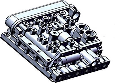
Fig. 1 A hydraulic buffering valve
The pressure regulating part of the buffering valve is the crucial part for guaranteeing its performance, and its structure diagram and hydraulic circuit are is shown in Figs. 2(a) and (b). As shown in Fig. 2(a), the accumulator spring is set between the spool of pressure control valve and the accumulator plunger. With the accumulator plunger moving, the pre-tightening force of the accumulator spring is changing, which will apply force on the spool of pressure control valve and control the pressure at Pg. From an empty clutch when it is not working to a working clutch with full torque, the pressure building up process in a clutch cylinder can beseparated into three stages: 1) the stage of fast filling; 2) the stage of pressure gradient rising; 3) the stage of pressure rapid rising.
2.1 Stage of fast filling
When a shifting signal is sent out, oil quickly flows into an empty clutch, as a result, pressure of Pg as shown in Fig. 2(b) (to the clutch) drops rapidly, and the spool of the pressure control valve and accumulator plunger do not move.
2.2 Stage of pressure gradient rising
Once the clutch is full of oil, pressure at Pg rises rapidly and increases to a certain value which will push the spool of the pressure control valve toward the right side. At the same time, the oil opens the bleeder valve and flows to the right side of the accumulator plunger, namely the side B. At the beginning, the bleeding hole on the spool of the pressure control valve has not been closed, and the oil at the side B will flow back to the tank through the hole and the reset valve. With the spool of the pressure control valve moving toward the right side, the bleeding hole will be closed and the pressure at the side B begins to increase. Since the buffer hole is very small, the pressure at the side B increases more slowly than that of the side A, and the spool of the pressure control valve keeps moving toward the right side, nearly closing the valve port between Pg and P finally. As a result, pressure at Pg stops increasing, and the pressure at the side B increases until it is equal to the pressure at the side A. Since the area of side B is bigger than that of side A, oil will push the accumulator plunger and the spool of the pressure control valve toward the left side, which will opens the valve port between Pg and P again. Then the pressure at Pg increases and the pressure at the side B increases more slowly than that of the side A because of the buffer hole. As a result, the spool of the pressure control valve is pushed to the right side again and nearly closes the valve port between Pg and P. Again and again, the hydraulic buffering valve works in this way, and the pressure at Pg increases gradually, until it is high enough to open the reset valve. Once the reset valve is opened, pressure oil flows into the space between the spool of the pressure control valve and the accumulator plunger, and under the pressure of the oil and the back force of the accumulator spring, the spool of the pressure control valve is pushed to the left most position and the accumulator plunger is pushed to the right most position.
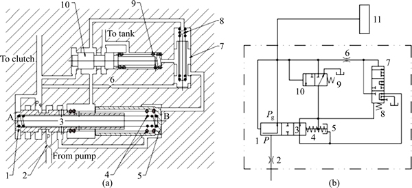
Fig. 2 Structure (a) and hydraulic circuit (b) of hydraulic buffering valve (1―Spool of pressure control valve; 2―Inlet orifice; 3―Bleeding hole; 4―Accumulator spring; 5―Accumulator plunger; 6―Buffer orifice; 7―Spool of bleeder valve; 8―Bleeder valve spring; 9―Reset valve spring; 10―Spool of reset valve; 11―Clutch)
2.3 Stage of pressure rapid rising
As the spool of the pressure control valve moves to the left most position and the accumulator plunger moves to the right most position, the valve port between P and Pg opens totally and pressure at Pg rises to the maximum value immediately.
3 Modeling and analysis
The starting pressure of buffering, the ending pressure of buffering and the gradient rising time affect the performance of the buffering valve directly. And they are calculated based on the structure diagram, as shown in Fig. 2(a). In the calculation, the friction force, inertia force and fluid power are neglected.
The buffering process begins when the spool of the pressure control valve is pushed towards the right side and nearly closed the valve port between Pg and P. And the equilibrium equation for the spool of the pressure control valve is shown as Eqs. (1) and (2).
 (1)
(1)
 (2)
(2)
where P0 is the starting pressure of buffering, MPa; d0 is the diameter of the spool of the pressure control valve, mm; K0 is the spring coefficient of the accumulator spring, N/mm; h0 is the precompression magnitude of the accumulator spring, mm; l0 is the relative displacement between the spool of the pressure control valve and the accumulator plunger at the beginning of the stage when pressure gradient rising starts, m.
The buffering process ends when the spool of the pressure reset valve opens. And the equilibrium equation for the spool of the pressure reset valve is shown as
 (3)
(3)
 (4)
(4)
where P1 is the ending pressure of buffering, MPa; d1 is the diameter of the spool of the pressure reset valve, mm; K1 is the spring coefficient of the reset valve spring, N/mm; h1 is the precompression magnitude of the reset valve spring, mm; l1 is the original opening of the pressure reset valve port.
The bleeding valve is used to accelerate the accumulator’s resetting and it has minor influence on the buffering process. Because of this, the bleeding valve is neglected in the calculation, the pressure gradient rising time can be calculated as Eq. (5) [18]:

 (5)
(5)
where f0 is the sectional area of the spool of the pressure control valve,  m2; f1 is the sectional area of the accumulator plunger,
  m2; f2 is the sectional area of the buffering orifice,
  m2; d2 is the diameter of the buffering orifice, m; L is the maximum relative displacement between the spool of the pressure control valve and the accumulator plunger, m; P2 is the pressure in the space between the spool of the pressure control valve and the accumulator plunger, MPa; Cq is the flow coefficient, 0.82 [19]; ρ is the oil density, kg/m3.
4 Simulation studies with AMESim
Imagine company of French launched AMESim (Advance Modeling Environment for Simulation of engineering systems) in 1995, which is used for multidisciplinary complex system simulation, and widely used in aerospace, aviation, ship building, weapons, vehicles, engineering vehicles, petroleum and petrochemical industries. In AMESim, users can focus on the physical system itself instead of tedious mathematical models, and develop models easily [20].
4.1 Modeling with AMESim
A model for the hydraulic buffering valve is developed in AMESim, as shown in Fig. 3, where the pump flow rate is 110 L/min, the system maximum pressure is 1.6 MPa, and the temperature is 80 °C. Besides, parameters of the model are shown in Table 2.
4.2 Simulated results
It is assumed that the following factors are negligible:1) the compressibility and the leakage of the oil; 2)The friction between the spool and the valve body and the hose and tube losses. The simulated pressure curve in the clutch cylinder is shown in Fig. 4.
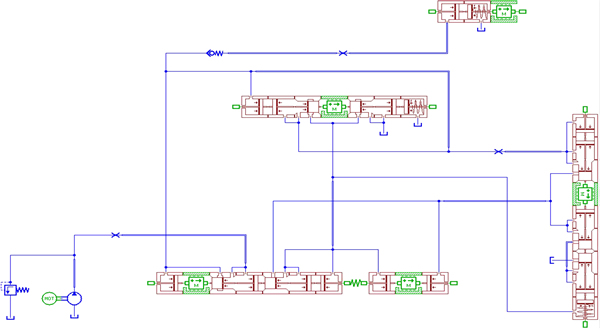
Fig. 3 Model for hydraulic buffering valve
Table 2 Parameters of hydraulic buffering valve model
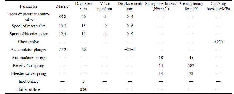
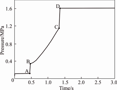
Fig. 4 Simulated pressure curve
4.3 Bench test
An engineering vehicle transmission and torque convertor test-station is designed and manufactured by Sichuan Chengbang Measurement and Control Technology Co.,Ltd, China. Experimental items that can be conducted on this test-station include transmission efficiency, shifting quality test, torque convertor property, etc. And parameters that can be measured on this test- station include rotate speed, torque, power, efficiency, oil pressure, oil flow rate, oil temperature, etc.
A bench test has been conducted based on a transmission which is controlled by the shift valve studied, as shown in Fig. 5.
In this test, the input rotate speed is 1800 r/min, the input torque is 135 N・m, and no load torque is appplied. By shifting from neutral gear to reverse gear and measuring the oil pressure of Pg in the hydraulic circuit when connected to the reverse clutch, tested pressure curve is obtained, as shown in Fig. 6. Besides, the simulated pressure curve and the tested pressure curve are compared in Table 3.
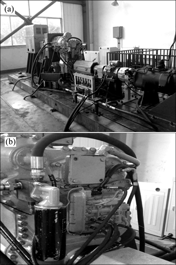
Fig. 5 Bench test
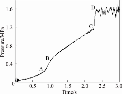
Fig. 6 Tested pressure curve
Table 3 shows that the simulated fast filling time and the gradient rising time are a little shorter than the tested results. Besides, the values at point A, point B, point C and point D of the simulated pressure curve are very close to those of the tested pressure curve. It shows that the simulated results agree well with the tested results, which indicates that the modeling process is correct and the model can be used to study the way how different valve parameters affectits buffering performance, i.e., the shifting quality.
5 Studies on key parameters of valve
In order to apply the similar types of hydraulic buffering valves on different types of equipments with varied working conditions, it is essential to study the way how different valve parameters affect its buffering performance, i.e., the shifting quality.
5.1 Studies on pre-tightening forces of accumulator spring
Figure 7 shows the pressure curves with 5 different pre-tightening forces of the accumulator spring.
It shows that the pre-tightening force of the accumulator spring affects the pressure at point B, the length of the fast filling time and the gradient rising time. When the pre-tightening force of the accumulator spring increases, the pressure at point B increases accordingly, the fast filling time and the gradient rising time will be shortened.
It can be concluded that the pressure at point B, the fast filling time and the gradient rising time can be modified by adjusting the pre-tightening force of the accumulator spring. And related studies have concluded that rise in the pressure at point B and shortening in the gradient rising time lead to a decrease in the heat produced during the shift process and an increase in shift shock at the same time [21, 22].
5.2 Studies on pre-tightening forces of reset valve spring
Figure 8 shows pressure curves with 5 different pre-tightening forces of the reset valve spring.
It shows that the pre-tightening force of the reset valve spring affects the pressure at point C and the length of the gradient rising time. When the pre-tightening force of the reset valve spring increases, the pressure at point C increases accordingly and the gradient rising time will be lengthened.
It can be concluded that the pressure at point C and the gradient rising time can be modified by adjusting the pre-tightening force of the reset valve spring. And related studies have concluded that rise in the pressure at point C and the enlongation of the gradient rising time lead to an alleviation in shift shock and an increase in heat produced during the shift process at the same time [21, 22].
Table 3 Comparison between of simulated pressure curve and tested pressure curve
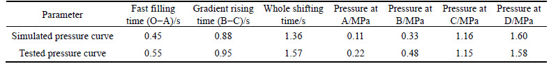
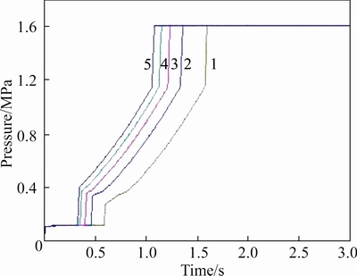
Fig. 7 Pressure curves with 5 different pre-tightening forces of accumulator spring (F1=36 N, F2=45 N, F3=54 N, F4=63 N, F5=72 N)
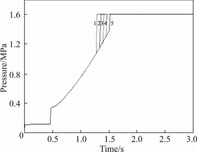
Fig. 8 Pressure curves with 5 different pre-tightening forces of reset valve spring (F1=168 N, F2=182 N, F3=196 N, F4=210 N, F5=224 N)
5.3 Studies on different sizes of buffer orifice
Figure 9 shows pressure curves with 5 different sizes of the buffer orifice.
It shows that the size of the buffer orifice affects the length of the gradient rising time and the pressure at point B obviously, besides, it has a little influnce on the length of the fast filling time. When the size of the buffer orifice increases, the gradient rising time will be shortened, the pressure at point B will rise, and the length of the fast filling time will be shortened slightly.
It can be concluded that the length of the gradient rising time and the pressure at point B can be modified by adjusting the size of the buffer orifice. And as mentioned before, rise in the pressure at point B leads to a decrease in the heat produced during the shift process and an increase in shift shock at the same time, while an enlongation of the gradient rising time leads to analleviation in shift shock and an increase in heat produced during the shift process.
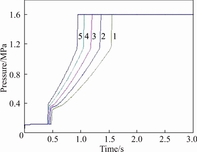
Fig. 9 Pressure curves with 5 different sizes of buffer orifice (D1=0.75 mm, D2=0.80 mm, D3=0.85 mm, D4=0.90 mm, D5=0.95 mm)
The pressure at point D is the same as the maximum pressure value in the system, which can be modified by adjusting the pressure modulating valve in the system.
In conclusions, by adjusting these key parameters of the hydraulic buffering valve, its output pressure curve during the shift process can be adjusted to meet different requirements for various engineering vehicles.
6 Conclusions
AMESim model of a hydraulic buffering valve has been developed and the influences of the key parameters of the hydraulic buffering valve on the output pressure curve have been studied. A bench test has been conducted and the test results agree well with the simulated results. The following conclusions can be drawn from the simulated studies.
1) The pressure at point B, the fast filling time and the gradient rising time can be modified by adjusting the pre-tightening force of the accumulator spring, and when the pre-tightening force of the accumulator spring increases, the pressure at point B increases, the fast filling time and the gradient rising time will be shortened.
2) The pressure at point C and gradient rising time can be modified by adjusting the pre-tightening force of the reset valve spring, and when the pre-tightening force of the reset valve spring increases, the pressure at point C will increase and the gradient rising time will be lengthened.
3) The pressure at point B and the gradient rising time can be modified by adjusting the size of the buffer orifice, and when the size of the buffer orifice increases, the pressure at point B will rise, and the gradient rising time will be shortened.
References
[1] KULKARNI M, SHIM T, ZHANG Y. Shift dynamics and control of dual-clutch transmissions [J]. Mechanism and Machine Theory, 2007, 42(2): 168-182.
[2] ZHAO Ding-xuan, CUI Gong-jie, LI Dong-bing. Shift quality of transmission system for construction vehicle [J]. Journal of Jiangsu University: Natural Science Edition, 2008, 29(5): 386-389. (in Chinese)
[3] ZHOU Xing-xing, WALKER P, ZHANG Nong, ZHU Bo, RUAN Jia-geng. Numerical and experimental investigation of drag torque in a two-speed dual clutch transmission [J]. Mechanism and Machine Theory, 2014, 79: 46-63.
[4] IQBAL S, AL-BENDER F, OMPUSUNGGU A P, PLUYMERS B , DESMET W. Modeling and analysis of wet friction clutch engagement dynamics [J]. Mechanical Systems and Signal Processing, 2015, 60-61: 420-436.
[5] OMPUSUNGGU A P, SAS P, van BRUSSEL H. Modeling and simulation of the engagement dynamics of a wet friction clutch system subjected to degradation: An application to condition monitoring and prognostics [J]. Mechatronics, 2013, 23(6): 700-712.
[6] OH J J, CHOI S B, KIM J. Driveline modeling and estimation of individual clutch torque during gear shifts for dual clutch transmission [J]. Mechatronics, 2014, 24(5): 449-463.
[7] SUN Xiao-long, LI Xiao-yan, ZHU You-li, XU Bin-shi. Failure analysis of wear of main clutch separating ring of heavy vehicles [J]. Central South University of Technology: Science and Technology, 2005, 52: 124-128.
[8] MENG Fei, TAO Gang, ZHANG Tao, HU Yi-huai, GENG Peng. Optimal shifting control strategy in inertia phase of an automatic transmission for automotive applications [J]. Mechanical Systems and Signal Processing, 2015, 60-61: 742-752.
[9] ZHAO Zhi-guo, HE Lu, ZHENG Zheng-xing, YANG Yun-yun, WU Chao-chun. Self-adaptive optimal control of dry dual clutch transmission (DCT) during starting process [J]. Mechanical Systems and Signal Processing, 2016, 68-69: 504-522.
[10] MENG Fei, TAO Gang, CHEN Hui-yan. Smooth shift control of an automatic transmission for heavy-duty vehicles [J]. Neurocomputing, 2015, 159: 197-206.
[11] van BERKEL K, HOFMAN T, SERRARENS A, STEINBUCH M. Fast and smooth clutch engagement control for dual-clutch transmissions [J]. Control Engineering Practice, 2014, 22: 57-68.
[12] LU Xi, WANG Shu-han, LIU Yan-fang, XU Xiang-yang. Application of clutch to clutch gear shift technology for a new automatic transmission [J]. Journal of Central South University, 2012, 19(10): 2788-2796.
[13] MA Biao, YE Ming. A study on dynamic response performance of vehicular power-shift hydraulic buffering valve [J]. Machine Design, 2004(4): 17-19. (in Chinese)
[14] MENG Fei, CHEN Hui-yan, ZHANG Tao, ZHU Xiao-yuan. Clutch fill control of an automatic transmission for heavy-duty vehicle applications [J]. Mechanical Systems and Signal Processing, 2015, 64-65: 16-28.
[15] BALAU A, CARUNTU C, LAZAR C. Simulation and control of an electro-hydraulic actuated clutch [J]. Mechanical Systems and Signal Processing, 2011, 25(6): 1911-1922.
[16] MENG Fei, SHI Peng, KARIMI H R, ZHANG Hui. Optimal design of an electro-hydraulic valve for heavy-duty vehicle clutch actuator with certain constraints [J]. Mechanical Systems and Signal Processing, 2016, 68-69: 491-503.
[17] WU Qiang, YAO Jun, FU Liang, GONG Xian-yuan. Hydraulic transmission and development of manipulation control technology for loader [J]. Mechanical Transmission, 2011, 35(4): 69-73. (in Chinese)
[18] HE Lei, HAN Jia-hua, HUANG Li. Study on pressure modulation valve for power shift transmission [J]. Coal Mine Machinery, 2012, 33(6): 86-88. (in Chinese)
[19] CHENG Da-xian. Handbook of mechanical design [M]. Beijing: Chemical Industry Press, 2008. (in Chinese)
[20] FU Yong-ling, QI Xiao-ye. System modeling and simulation reference manual of LMS Imagine. Lab AMESim [M]. Beijing: Beihang University Press, 2011. (in Chinese)
[21] LIN Feng, LIU Ying, MA Biao. A study of the influence of pressure characteristicson the shift clutch engagement performance [J]. Journal of Xiangtan University: Natural Science, 2004, 26(3): 95-98. (in Chinese)
[22] MA Biao, LIU Ying, CHEN Jian-wen. Study on dynamic performance in engagement process of power shift-steering transmission shift clutch [J]. China Mechanical Engineering, 2000, 11(6): 691-694. (in Chinese)
(Edited by FANG Jing-hua)
Cite this article as: WANG Fei, WANG Yu, HAN Jia-hua, YAO Jin. Experimental and simulated studies on hydraulic buffering valve for ZF-4WG308 power-shift transmission [J]. Journal of Central South University, 2017, 24(8): 1801-1807. DOI: https://doi.org/10.1007/s11771-017-3588-4.
Foundation item: Project(51077096) supported by the National Natural Science Foundation of China; Project(2012940-15-3) supported by the Scientific Research Foundation for the Returned Overseas Chinese Scholars, State Education Ministry
Received date: 2016-01-13; Accepted date: 2016-05-13
Corresponding author: HAN Jia-hua, Associate Professor, PhD; Tel: +86-13980040082; E-mail: 13980040082@139.com

