
Forming process of cross-connected finned micro-grooves in copper strips
CHI Yong(池 勇), TANG Yong(汤 勇), CHEN Jin-chang(陈锦昌),
DENG Xue-xiong(邓学雄), LIU Lin(刘 林), WAN Zhen-ping(万珍平), LIU Xiao-qing(刘晓晴)
College of Mechanical Engineering, South China University of Technology, Guangzhou 510640, China
Received 25 July 2006; accepted 19 January 2007
Abstract: Using ploughing-extrusion method, a cross-connected finned micro-grooves structure was formed on the surface of copper strips with thickness of 0.4 mm. The structure was fabricated by making ‘V’-grooves in copper strips and perpendicular ‘V’-grooves on the opposite side that intersect the first set of grooves. Micro pores appear at the intersection of these cross-connected grooves, and micro fins appear on the groove fringes. So it can be defined as ‘pore-groove-fin’ structure. The preferable ‘pore-groove-fin’ structure can be obtained under the condition that the tool edge inclination angle (χγ) is 45?, both the major extrusion angle (γo) and the minor extrusion angle  are 30?, both the major formation angle (β) and the minor formation angle (β′) are 10?, the ploughing-extrusion depth (fd) is 0.32 mm and the groove pitch is 0.4 mm on surfaces A and B. The formed included angle of groove A is 70?, and the groove depth is 0.3 mm, while the included angle of opposite perpendicular groove B is 20? with the groove depth of 0.35 mm. The obtained fin height is 0.15 mm, the elliptical pore length is 0.2 mm and the width is 0.05 mm. Experiments show that fd has the greatest influence on the formation of micro pores. Bulges appear on the opposite surface B when the ploughing-extrusion depth on surface A (fdA) reaches a critical value. The ploughing-extrusion depth on surface B (fdB) has great influence on the re-growth of fin structure.
Key words: copper stripe; micro groove; fin; ‘pore-groove-fin’ structure; boiling enhancement; ploughing-extrusion
1 Introduction
The cross-connected grooves have excellent boiling enhancement performance. The structure is fabricated by making grooves in a thin plate of material and perpendicular grooves on the opposite side that intersect the first set of grooves. This forms a structure with greater surface area than the original surface and allows for nucleation, reentrant cavities, and room for the bubbles to escape. This structure has been widely used in thermosyphon, capillary pump loops, loop heat pipes and other two-phase cooling devices to improve the evaporating efficiency. So it has wide prospect in the high heat flux dispersion of microelectronics cooling.
As early as 1931, it was known that the ‘roughness’ could improve nucleate boiling performance[1]. In 1980, NAKAYAMA et al[2-3] brought forward the ‘pore-groove’ geometry structure. The experiment showed that this structure could reduce the wall superheat as much as 80%-90% than the smooth one. The experiment results from RAMASWAMY et al[4] showed that the enhanced structure demonstrated almost 2.5 times increase in the heat transfer compared with a solid block of the same size. MURTHY et al[5] verified the boiling enhancement structure resulted in a significant decrease in the wall temperature. GHIU et al[6] and RAMASWAMY et al[7] visualized the boiling enhancement process of the structure by NAKAYAMA. Aiming at the structure presented by NAKAYAMA, GHIU et al[8] made the comparison between the performances of single-layer boiling enhancement structures with different groove widths and groove intervals. Welding 6 pieces of boiling enhancement structure together and putting it into a thermosyphon, PAL et al[9] found that this enhancement structure could increase the critical heat flux and reduce the incipience overshoot at the surface temperature above the saturation value. CHIEN et al[10-11] discovered the small diameter of pores that was suitable for the strengthened boiling of liquid with low heat flow density.
However the ‘pore-groove’ geometry is usually fabricated with expensive or complex methods such as photolithography, chemically etching, wafer dicing saws, or micro milling. GHIU[8] used different ways to machine boiling enhancement structure with different groove widths and groove intervals. The ‘pore-groove’ structures that are 0.6 mm in groove depth, 0.7 mm in groove intervals, and 0.065, 0.085 and 0.105 mm in groove width, respectively, were made by nickel-diamond blade. By wire electro-discharge machining, the structures with groove width of 0.36 mm and 0.47 mm were made, respectively. Thinner and denser ‘pore-groove’ structure could be formed by photolithography and chemical etching. NGAI et al[12] employed glancing angle deposition to machine the ‘pore-groove’ in nanometer scale. RAMASWAMY et al[7] used photolithography to form the structure on silicon sheet and wet etching with 40% KOH solution, then got the ‘pore-groove’ structure with 0.2 mm in width and 0.1 mm in intervals. But all the methods mentioned above are just suitable for machining the ‘pore-groove’ structure with regular rectangle groove or ‘U’-shape groove. XIA et al[13] used chopping- extruding to obtain the integral fin tube. TANG et al[14-15] got the 3-D fin structure on the surface of stainless steel by pre-rolling and ploughing. But the aforementioned experiments are all about the machining on the outer wall or on the single surface of stainless steel.
In this study, the cross-connected finned micro grooves in copper strip were formed by ploughing- extrusion. This structure has more geometry characteristics than the conventional ‘pore-groove’ structure. On the fringe of grooves, there are micro fins that are advantageous for the core forming. So the cross-connected finned micro groove structure can be defined as ‘pore-groove-fin’ structure. The ‘pore-groove-fin’ structure on the two surfaces of copper strips was fabricated by ploughing-extrusion process.
2 Experimental
The cross-connected finned micro-grooves structure was fabricated by making ‘V’-grooves in copper strips and perpendicular ‘V’-grooves on the opposite side that intersect the first set of grooves. Micro pores appeared in the intersection of the cross-connected grooves, and micro fins appeared on the groove fringes. ‘V’-shape grooves were manufactured by ploughing-extrusion with special tool on the two surfaces. The schematic diagram of the tool is shown in Fig.1. The ploughing edge, the major extrusion face Aγ, the minor extrusion face  , the major forming face Aβ, the minor forming face
  and the tool flank Aα were ground by high speed steel with dimensions of 2 mm×10 mm×200 mm. The O―O section of the tool is a wedge. The front end is the ploughing edge which ploughs the metal and makes the metal flow along the major extrusion face and the minor one. The major extrusion face Aγ generally extrudes and ploughs the split metal and makes it flow along the major forming face Aβ, and then the metal forms the grooves under the extrusion of the major forming face Aβ. The minor extrusion face trims the fins and makes them higher. Owing to the trimming and extruding effect from the adjacent grooves on the minor forming face, when the next micro-groove is formed, the ratio of depth to width is further increased. So the major forming angle β should be larger than minor forming angle β′ to ensure the symmetry of ‘V’-shape groove.
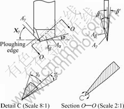
Fig.1 Schematic diagram of ploughing-extrusion tool
The experiment was carried out on the planer B6050B. The workpiece is red copper strip with depth of 0.4 mm, which is made of material T2, and the tool is made of W18Cr4V alloy. It is defined that surface A is the one processed firstly and B is the opposite surface of A. As shown in Fig.2, the workpiece was fixed on the work table, and then the tool ploughed the copper strip along the minus Y and formed ‘V’-shape micro grooves. The tool ploughed the strip in one feed, the workpiece then moved along minus X once to get ready for the next ploughing-extrusion process. Meanwhile the formed ‘V’-shape micro grooves were modified and the fin got heightened. After all the grooves were formed on the surface A, the strip was turned over and rotated with 90? to make the formed grooves on the surface A vertical to the ploughing direction. With the same method, another group of grooves were formed on the opposite surface B. To avoid bulging, one end of the strip was fixed, while the other end could extend and shrink freely along the axis X.
Since the tool is thin, the component force of tool along axis X during the ploughing-extrusion process should be reduced to prevent the tool from deforming and creating zigzag interfering on micro-groove. The component force of axis X is mainly composed of the extrusion and friction between the workpiece and the major/minor extruding face. The extruding force and the friction from the two extrusion faces are equal in quantity and are reverse in direction, so the relation of the major/minor extrusion angle is
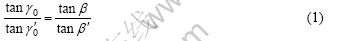
where γ0 is the major extrusion angle,  is the minor extrusion angle, β is the major forming angle, and β′ is the minor forming angle.
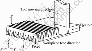
Fig.2 Forming process of cross-connected finned micro- grooves
3 Results and discussion
3.1 Forming process and mechanism
The ploughing-extrusion process of single ‘V’-shape micro groove comprises three stages: chopping, extruding and forming. Firstly, the metal is chopped by the ploughing edge and flows towards the extrusion faces. Secondly, due to the extrusion from the major/minor extrusion faces, the metal at the bottom and the flank of ‘V’-shape grooves flows upwards and forms bulges, then the split metal forms ‘V’-shape grooves under the extrusion from the major and minor forming faces. Fig.3 shows the continuous metal streamline around the grooves. The metal contacted with the extrusion face of the tool is extruded and deformed plastically, and the metal at the bottom of ‘V’-shape grooves flows upwards along the extrusion face and forms the continuous streamline. Under the extrusion from the extrusion faces and the un-deformed metal, i.e. the metal at the bottom and middle of the groove, flows toward the fringe of grooves. As the upper surface of copper strip is free one, the flowing metal accumulates around the fringe and forms bulges where the streamlines are sparse.
Owing to the friction between the extrusion face and the forming face on the groove wall, when the tool moves, the deformed metal is detained on the forming face and follows with the tool. So when the micro- grooves on surface B is formed and the tool departs from surface A, the metal detained on the tool surface will go on plastic deformation and protrude from groove surface on surface A, and then form the sectional bulge, as shown in Fig.4. Under the restriction from metal streamline, the metal around the ploughing edge will yield and deform plastically when the tool cuts into the grooves on surface A, and forms depression in the grooves. The friction from the extrusion face and forming face on groove wall drives the detained metal to go forward, and the ‘V’-shape grooves on surface A distort when the tool goes though surface A. Finally the wave-like surface forms from the two grooves wall on surface A, as shown in Fig.4
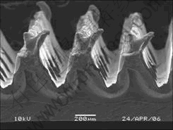
Fig.3 SEM image of end face after ploughing-extrusion
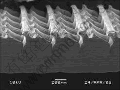
Fig.4 SEM image of grooves on surface A after ‘V’-shape grooves formed on surface B
During the formation of ‘V’-shape grooves on surface B, when the ploughing-extrusion depth connects with the ‘V’-shape groove on surface A, the formation of ‘V’-shape grooves on surface B will affect and distort the appearance of ‘V’-shape grooves on surface A. the larger the ploughing-extrusion depth on surface B is, the larger the influence is, and the more serious deformation is. Less metal will have plastic deformation when it goes nearer the top of ‘V’-shape groove on surface A, the ductile fracture will appear when the metal cannot sustain the plastic deformation any longer, and then the micro pores appear, as shown in Fig.5.
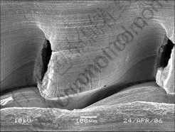
Fig.5 SEM image of micro pores of cross-connected finned micro grooves on surface A
3.2 Influence of ploughing-extrusion depth
The ploughing-extrusion depth has the greatest influence on the ‘pore-groove-fin’ structure. When the sum of ploughing-extrusion depths of surface A and surface B equals the thickness of copper strip (0.4 mm), the micro grooves on the two surfaces should penetrate each other. But owing to good plasticity of copper strip, the bottom of micro groove deforms plastically and protrudes during the ploughing-extrusion process, metals are not chopped apart thoroughly, and micro pores can not be formed. Only when the sum of ploughing- extrusion depth surpasses the thickness of copper strip even reaches a critical value, the plastic deformation at the bottom of the grooves reaches the limit and the crack appears, then the micro pores come into being. The increased sum of ploughing-extrusion depth on surfaces of A and B makes the crack more distinct, and the formed micro pore has larger dimension.
Fig.6 shows the experiment result carried out at different ploughing-extrusion depths, under the condition that the edge inclination angle (χγ) is 45?, the major extrusion angle (γ0) is 30?, the minor extrusion angle is 11?, the major forming angle (β) is 15?, and the minor forming angle (β′) is 5?.
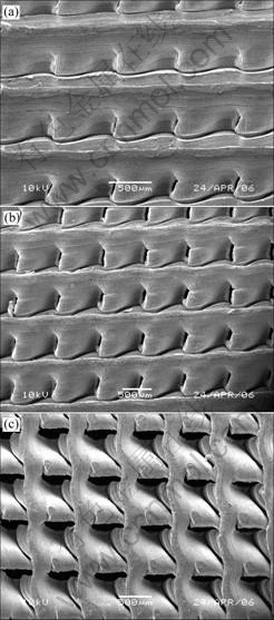
Fig.6 SEM images of ‘pore-groove-fin’ structure at different ploughing-extrusion depths (surface A): (a) fdA=0.20 mm, fdB= 0.26 mm; (b) fdA=0.26 mm, fdB =0.32 mm; (c) fdA=0.32 mm, fdB =0.40 mm
Fig.6(a) shows the result when the ploughing- extrusion depth on surface A (fdA) is 0.20 mm, and the ploughing-extrusion depth on surface B (fdB) is 0.26 mm, the sum of ploughing-extrusion depth is 0.06 mm larger than the thickness of copper strip. From Fig.6(a), it can be seen that the micro grooves on surface A undergo the distortion due to the function from micro grooves on surface B and form the wave-like surface, while the cracks appear on the minor extrusion face and the minor forming face. As a result of machining error and the inhomogeneity of the material, the cracks are not stable, some just come out, and some change into the micro pores.
Fig.6(b) shows the result when fdA is 0.26 mm, and fdB is 0.32 mm, the sum of ploughing-extrusion depth is 0.18 mm larger than the thickness of copper strip. The picture shows clearly that the dimension of micro pores is larger and more stable, their shapes are pretty homogeneous.
Fig.6(c) shows the result when fdA is 0.32 mm, and fdB is 0.40 mm, the sum of ploughing-extrusion depth is 0.32 mm larger than the thickness of copper strip. Since the ploughing-extrusion depth is larger and the metal at the bottom is thin. During the processing on surface B, due to the week strength, the metal at the top of groove on surface A slips forward and forms the ridge except the extruding deformation occurring in the micro grooves. And the wrinkle micro grooves appear on the fringe of pore. Meanwhile, with the increase in extruding depth on the two surfaces, the dimension of pore is enlarged further.
3.3 Influence of forming angle
Forming angle decides the final geometry of micro grooves, thus determines the final plastic deformation during the extruding process, too. Bigger forming angle makes tool edge blunter, and has fewer ploughing effect but more extruding effect on the metal. Most of the metal in grooves flows towards the bottom and the side under the extruding. On the other hand, smaller forming angle makes the tool edge sharper, and has more ploughing effect on metal and fewer extruding effect on metal. Few split metal undergoes plastic deformation. So the metal can be split easily and micro grooves form.
Fig.7(a) shows the obtained structure on surface A under the condition that χγ is 45?, γ0 is 30?, is 21?, β is 15?, and β′ is 10?, fdA is 0.20 mm, and fdB is 0.26 mm. Compared with Fig.6(a), only the minor forming angle is increased by 5?. The crack appears on one side of the minor forming face and the micro forms, as shown in Fig.6(a). While in Fig.7(a), with the increased minor forming angle, there is no crack, the minor forming face becomes symmetric to one side of the major forming face and even the bulges generate, but no micro pore appears. When β is 15? and β′ is 5?, the difference between these two angles makes most metal be chopped to one side of the major forming face, and under the further extruding from the major extrusion face and major forming face, this metal flows towards the micro grooves on surface A. The micro grooves on surface A are divided into wave-like array by micro grooves on surface B. Since the metal that joins the plastic deformation is diminished on the one side of the minor forming face, the same ploughing-extrusion depth creates the same deformation, so the metal with week strength tends to break and cracks forms. The more the sum of ploughing- extrusion depth on the two surfaces surpasses the thickness of copper strip, the sharper the deformation is, and the bigger the cracks are, therefore the bigger the formed micro pores become. The changing trend is obvious in Fig.6.
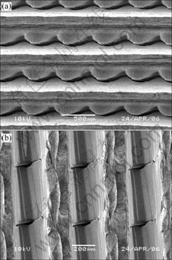
Fig.7 SEM images of ‘pore-groove-fin’ structure at different forming angles: (a) β=15?, β′=10?, fdA=0.20 mm, fdB=0.26 mm (surface A); (b) β=10?, β′=10?, fdA=0.32 mm, fdB=0.32 mm (surface B)
Fig.7(b) shows the obtained structure on surface B under the condition that χγ is 45?, both γ0 and are 30?, both β and β′ are 10?, both fdA and fdB are 0.32 mm. The total forming wedge angle is 20?, micro pores can generate on the sharp edge easily. The symmetry of the tool makes metal flow to both the major and minor forming faces uniformly, the cracks appear at the tip of the tool and extend along the two sides of the major and minor forming faces, then the elliptical micro pores are formed symmetrically. The structure with these elliptical micro pores is different from that formed by the tool with asymmetric major and minor forming angle.
3.4 Formation of fin structure
Under the extruding from the tool, when the ploughing-extrusion depth of surface A reaches a certain value, bulges will be formed on the opposite surface of the copper strip, as shown in Fig.8(a). During the machining of micro grooves on surface B, the bulges grow higher under the further extruding of tool. The detained metal is driven forward by the friction of the extrusion face and the forming face on groove wall. The bulges also slip followed by the tool, and then under the friction and extruding, they deform plastically and form denticular fins, as shown in Fig.8(b). Fig.9 shows the SEM image of fin structure.
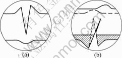
Fig.8 Formation process of fin structure: (a) Bulge formation; (b) Fin formation and heightening
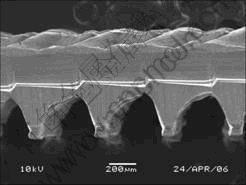
Fig.9 SEM image of fin structure
The ploughing-extrusion depth has the greatest influence on the form of the fin structure. When the process redundancy of ploughing-extrusion is less than 0.1 mm, for the copper strip with thickness of 0.4 mm, distinct bulges appear on the opposite of the tool tip.
During the ploughing-extrusion process of single micro groove, fewer process redundancy leads to more distinct bulges, and this forming process influences the groove that has just been created when the groove intervals are small, the formed bulges affect and shorten each other. The deeper the tool ploughs and extrudes the metal on surface B, the more favorable it is for the re-heightening of the bulges, and more distinct the fin structure is.
The experiments show that a preferable ‘pore-groove-fin’ structure can be obtained under the condition that χγ is 45?, both γ0 and  are 30?, both the major formation angle and minor formation angle are 10?, both fdA and fdB are 0.32 mm, as shown in Fig.7(b) and Fig.9, in which pores, grooves and fins are included. Moderate increase in ploughing-extrusion depth on surfaces A and B can create bigger micro pores and higher micro fins.
4 Conclusions
1) The cross-connected finned micro-groove structure, which comprises pore, groove and fin, can be manufactured by ploughing-extrusion process. The preferable ‘pore-groove-fin’ structure can be obtained under the condition that the tool edge inclination angle (χγ) is 45?, both the major extrusion angle (γ0) and the minor extrusion angle are 30?, both the major formation angle (β) and the minor formation angle (β′) are 10?, the ploughing-extrusion depth (fd) is 0.32 mm and the groove pitch is 0.4 mm on the two surfaces.
2) The ploughing-extrusion depth has the greatest influence on the formation of micro pores. The bigger the difference between the sum of ploughing-extrusion depth on the two surfaces and the thickness of copper strip is, the bigger the micro-pores are. Smaller forming angle makes the metal to be split easily and micro grooves form.
3) The bulges formed during the ploughing- extruding process on surface A affect the formation of fin structure, bigger bulges make the fin structure more distinct on surface B. The ploughing-extrusion depth of surface B has greater influence on the re-growth of fin structure.
References
[1] Webb R L. Odyssey of the enhanced boiling surface [J]. J Heat Transf, 2004, 126(6): 1051-1059.
[2] Nakayama W, Daikoku T, Kuwahara H, Nakajima T. Dynamic model of enhanced boiling heat transfer on porous surfaces (part I): Experimental investigation [J]. J Heat Transf, 1980, 102(3): 445-450.
[3] Nakayama W, Daikoku T, Nakajima T. Effects of pore diameters and system pressure on saturated pool nucleate boiling heat transfer from porous surfaces [J]. J Heat Transf, 1982, 104(2): 286-291.
[4] Ramaswamy C, Joshi Y, Nakayama W, Johnson W B. Thermal performance of a compact two-phase thermosyphon: Response to evaporator confinement and transient loads [J]. J Enhanced Heat Transfer, 1999, 6(2/4): 279-288.
[5] Murthy S S, Joshi Y K, Nakayama W. Single chamber compact two-phase heat spreaders with microfabricated boiling enhancement structures [J]. IEEE Trans Compon Packag Technol, 2002, 25(1): 156-163.
[6] Ghiu C D, Joshi Y K. Visualization study of pool boiling from thin confined enhanced structures [J]. Int J Heat Mass Transf, 2005, 48(21/22): 4287-4299.
[7] Ramaswamy C, Joshi Y, Nakayama W, Johnson W B. High-speed visualization of boiling from an enhanced structure [J]. Int J Heat Mass Transf, 2002, 45(24): 4761-4771.
[8] Ghiu C D, Joshi Y K. Boiling performance of single-layered enhanced structures [J]. J Heat Transf, 2005, 127(7): 675-683.
[9] Pal A, Joshi Y K, Beitelmal M H, Patel C D, Wenger T M. Design and performance evaluation of a compact thermosyphon [J]. IEEE Trans Compon Packag Technol, 2002, 25(4): 601-607.
[10] Chien L H, Webb R L. Parametric studies of nucleate pool boiling on structured surfaces (part I): Effect of tunnel dimensions and comparison of R-11 [J]. J Heat Transfer, 1998, 120: 1042-1048.
[11] Chien L H, Webb R L. Parametric studies of nucleate pool boiling on structured surfaces (part II): Effect of pore diameter and pore pitch [J]. J Heat Transfer, 1998, 120: 1048-1054.
[12] Ngai S, Leontiev A I, Lloyd J R, Malyshenko, S P. Creation of nano-scaled surface structure for the enhancement of boiling heat transfer [C]//IMECE 2004. New York: ASME, 2004: 331-339.
[13] Xia W, Wu B, Tang Y, Ye B Y. On chopping-extrusion of integral-fin copper tubes [J]. J Mater Process Technol, 2003, 138: 385-389.
[14] Tang Y, Xia W, Liu S D, ZENG Z X, YE B Y. Fin formation model during pre-roll ploughing of copper 3D outside fin tube [J]. Trans Nonferrous Met Soc China, 2001, 11(5): 712-716.
[15] Tang Y, Liu S D, Xia W, ZENG Z X, YE B Y. The establishment and analysis of fin formation model during ploughing process [J]. J Mater Process Technol, 2003, 138: 390-393.
Foundation item: Projects(50436010, 50605023, 50675070) supported by the National Natural Science Foundation of China; Project(04105942) supported by the Natural Science Foundation of Guangdong Province, China
Corresponding author: TANG Yong; Tel: +86-20-87114634; E-mail: ytang@scut.edu.cn
(Edited by CHEN Wei-ping)

