
Forming method of axial micro grooves inside copper heat pipe
LI Yong(�� ��), XIAO Hui(Ф ��), LIAN Bin(�� ��), TANG Yong(�� ��), ZENG Zhi-xin(��־��)
School of Mechanical and Automotive Engineering, South China University of Technology,
Guangzhou 510640, China
Received 8 October 2007; accepted 29 August 2008
Abstract: The high-speed oil-filled ball spinning and drawing process was put forward to manufacture the axially grooved heat pipe with highly efficient heat-transfer performance, and the forming mechanism of micro-grooves inside the pipe was investigated. The key factors influencing the configurations of micro-grooves were analyzed. When the spinning depth varies between 0.4 mm and 0.5 mm, drawing speed varies from 200 mm/min to 450 mm/min, rotary speed is beyond 6 000 r/min and working temperature is less than 50 ��, the grooved tubes are formed with high quality and efficiency. The ball spinning process uses full oil-filling method to set up the steady dynamic oil-film that reduces the drawing force and improves the surface quality of grooved copper tube.
Key words: ball spinning; micro groove; heat pipe; multi-tooth mandrel
1 Introduction
Recently, the thermal management of electronic systems has become a key technique in many products. This is driven by the rapid progress in advanced high power electronic packages. Some existing heat removal techniques such as air-cooled finned heat exchangers can no longer satisfy the needs of high specifications for compactness, reliability and performance[1-3].
At present, silicon, diamond, copper or other materials with high thermal conductivity are mainly used for producing the radiators for electronic products with high heat flux density[4-6]. Due to the better thermal conductivity, temperature uniformity and faster response, the copper heat pipes are of broad prospects for application[7-10]. There are several types of cross- section of grooves inside grooved copper heat pipes, such as triangular, rectangular, trapezoidal, and inverse trapezoidal types, which results in different heat transfer capability. How to produce ideal inner micro grooves is the crucial problem to the copper heat pipes. Ball spinning, a special process to manufacture wall-thinned high-precision tubes with small diameters has been used widely in recent years. Many researchers are trying to develop various equipments to meet their requirements using ball-spinning process, such as to produce conical wall tubes, and stepped wall tubes. Special importance is focused on the relationship among the ball size, the axial feed rate and the number of balls[11-16].
In this work, an oil-filled ball spinning process to machine the axially inner micro grooves by extruding the copper tube with fixed multi-tooth mandrel is presented. The effects of the mandrel geometry and spinning process parameters are studied to find out the optimum machining conditions. Compared with the conventional ways of machining micro grooves, such as extruding, mechanical notching and chemical etching, this process is simpler and easier, as well as requires less equipments. Fig.1 shows the image of axially micro grooved copper tubes (the outer diameter is 6.0 mm) and multi-tooth mandrel.
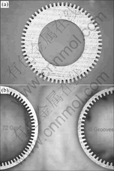
Fig.1 Images of multi-tooth mandrel (a) and axially inner grooved copper tubes (b)
2 Experimental
A fully oil-filled high-speed spinning machine is developed and employed as the experimental setup, as illuminated in Fig.2. This manufacturing process includes extruding and drawing processes. High-speed motor drives the spinning body, which makes steel balls rotate. Meanwhile, the steel balls and multi-tooth mandrel extrude the raw copper tube that is drawn by working workbench in axial direction. During machining process, the multi-tooth mandrel only forms the inner micro-grooves and does not produce any chip, therefore, the mandrel is different from the conventional cutting tools, and can be classified as a forming tool.
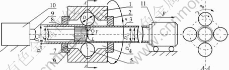
Fig.2 Schematic diagram of experimental setup of spinning process: 1 Spinning body; 2 Radius regulation die; 3 Axially inner grooved copper tube; 4 Oil-filled chamber; 5 Steel ball; 6 Multi-tooth mandrel; 7 Radius reduction die; 8 Raw copper tube; 9 Mandrel shaft; 10 Mandrel fixture; 11 Moving workbench (n��Spinning body planetary rotation speed; n0��Steel ball planetary rotation speed; n1��Steel ball revolution speed; Dwl��Outer diameter of raw copper tube; Dw0��Inner diameter of raw copper tube; Ddl��Outer diameter of grooved copper tube; Dd0��Inner diameter of grooved copper tube)
The fixed multi-tooth mandrel and the spinning balls work together to make the arced teeth of the mandrel split the inner metal of the copper tube. With the increase of drawing force and the spinning depth, the deformed metal flows in axial, radial and tangential directions. The plastic deformation in axial direction prolongs the copper tube. The plastic deformation in radial direction forms teeth and grooves. Due to the dramatic deformation of the metal, a great deal of heat is produced. To solve this problem, the chamber among radius regulation die, radius reduction die and spinning body is filled with pressured lubrication-oil. Thus, the wall metal of the raw copper tube can be smoothly extruded, prolonged and finally developed into inner grooves and teeth (fins).
The cross-section of the multi-tooth mandrel is shown in Fig.1, and the parameters of the mandrel geometry are listed in Table 1.
Table 1 Parameters of multi-tooth mandrel (W18Cr4V)

The outer diameter of raw copper tube (Copper, TP2) is 7.0 mm and its wall thickness is 0.6 mm. The groove parameters are listed in Table 2.
Table 2 Dimensions of grooved copper tube

3 Results and discussion
Based on the experiments, the main factors include the geometry and working position of the multi-tooth mandrel, spinning depth, drawing speed, rotary speed, lubrication state in contact area and working temperature (temperature of the grooved tube at the outlet of the radius regulation die).
3.1 Effects of multi-tooth mandrel
Both of the geometrical parameters and the working position of the mandrel affect the configurations of the micro groove and grooved appearance, which makes the grooved heat pipe have different heat transfer capability.
1) Geometrical parameters of mandrel
The mandrel geometry is key to the groove forming. The two ends of the mandrel are arced, and the arced teeth of the front end (close to steel ball) meet the deformed metal firstly, and support the deformation forces, torsional moments and impacts from spinning balls. The arced teeth play a chopping and extruding role, and the configurations of the teeth control the profiles of the micro-grooves. In this design, the end arc radius is 0.3 mm(see Fig.3(a)). The material property and working position of mandrel are essential to its working life, and mandrel teeth is broken or collapsed easily during the course of work(see Fig.3(b)). According to the demands of heat transfer capability of the copper heat pipe and manufacturing process of the mandrel, the mandrel teeth are usually designed to be rectangular cross-section in axial direction.
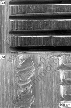
Fig.3 SEM images of multi-tooth mandrel: (a) Arc of end; (b) Broken and collapsed teeth
2) Working position of mandrel
During the manufacture of micro-grooves, the working position of the mandrel has a direct relationship with the shape and direction of the micro-grooves under certain vibrating conditions. There is a YOZ system of coordinates as shown in Fig.2, and the O point is the central point of the minimum equivalent diameter of the four spinning balls. Supposing that the Y-coordinate of the front end-face centre-point of the mandrel is L, the experimental results are as follows. If 0��L��3, the smooth surfaces of micro-grooves are produced; If �C0.5��L��0, surfaces are terraced; If (�C1.0 to �C0.8)��L���C0.5, surfaces are spiral. If L continues to decrease, the micro-grooves become shallower. Instead, if the multi-tooth mandrel goes over O point of the minimum equivalent diameter, i.e. L��3, axial grooves with smooth wall can also be processed, but the mandrel teeth are broken or crushed easily as the drawing force increases. Three types of micro-grooves produced by multi-tooth mandrel at different positions are shown in Fig.4.
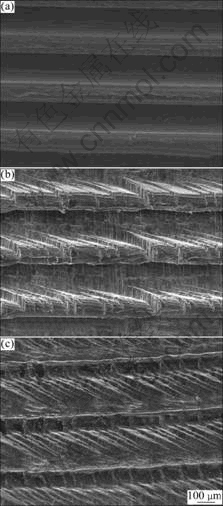
Fig.4 Micro-grooves produced by multi-tooth mandrel at different positions: (a) Smooth micro-grooves; (b) Terraced micro-grooves; (c) Spiral micro-grooves
3.2 Effect of spinning depth
Spinning depth (ap) is the reduction rate between the outer diameter of raw copper tube and the outer diameter of grooved tube, where ap=Dw1-Dd1. Fig.5 shows the different depths of micro-grooves under different spinning depth (ap).
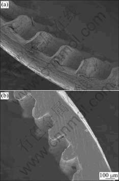
Fig.5 Micro-groove depth under different ap: (a) ap=6 mm;(b) ap=6.3 mm
As the spinning depth (ap) increases, the wall thickness of the grooved tube (tl) decreases gradually. In this situation, the ratio of the depth of the micro-groove (hp) to the wall thickness (tl) is defined as spinning ratio ��:
�ˣ�hp/t1 (1)
The relationship between �� and ap is shown in Fig.6. The spinning ratio increases with the increase of the spinning depth until the ratio reaches 1. If the ratio exceeds 1, the grooved tube is easy to break.
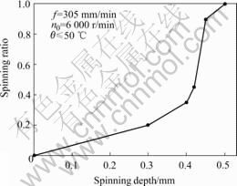
Fig.6 Relationship between �� and ap
3.3 Effect of drawing speed
The relationship between spinning ratio and drawing speed is shown in Fig.7. As the drawing speed increases, the groove depth reduces. But if the drawing speed reaches a certain value, the grooved tube is broken easily.
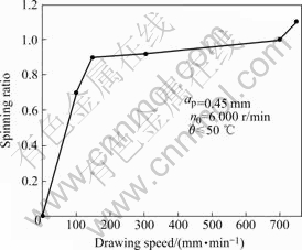
Fig.7 Relationship between �� and f
3.4 Effect of spinning speed
The spinning speed (n) means the planetary rotation speed of spinning body. If the spinning speed increases, the drawing force and outer surface roughness of grooved tube decrease. If the spinning speed is below 3 000 r/min, the copper tube is easy to break unless the drawing speed is very low. The relationship between spinning speed and drawing force is shown in Fig.8. The indentation of the spinning ball in breakpoint caused by low spinning speed can be seen in Fig.9.
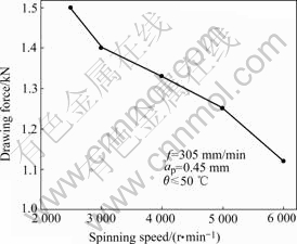
Fig.8 Relationship between n and drawing force

Fig.9 Breakage views of breakpoint
Based on the experiments of micro-groove forming, the dynamic oil-film is set up in spinning contact area under high spinning speed and full oil-filling conditions, which reduces the drawing resistance and improves the surface quality of grooved tube during the manufacture of micro grooves. Furthermore, the problems of cooling, lubrication and vibration in the forming process are solved efficiently. The fully oil-filled ball-spinning process is a new kind of method for manufacturing micro heat pipes.
The experiment results show that the lubrication state is steady in spinning contact area and the drawing force doesn��t decrease when the spinning speed is more than 8 000 r/min.
3.5 Effect of working temperature
The temperature of the spinning region is hard to measure directly, so the temperature of grooved tube at outlet of the radius regulation die is measured as the working temperature. The investigations show that when the temperature of the grooved tube is less than 40 ��, namely �ȡ�40 ��, the working temperature has no significant effect upon the process; when ��=40-60 ��, the effect is significant; and when �ȡ�60 ��, the spinning process can not continue. Fig.10 shows the outer surface quality of the grooved tube under different working temperature.
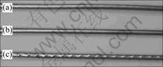
Fig.10 Outer surface of grooved tubes under different working temperatures: (a) 50 ��; (b) 40 ��; (c) 60 ��
4 Conclusions
1) The forming process of the axially inner micro-grooves of copper heat pipe via oil-filled ball spinning process with high spinning speed, is feasible for industrial manufacture of the axially grooved copper heat pipes.
2) The shape of the mandrel determines the geometrical profile of the grooves, and the position of the mandrel affects the depth and path of the grooves. With the increase of the spinning depth, the micro-groove depth increases and the wall thickness decreases, which makes the tube break easily when the ratio of those two reaches 1. When the working temperature is less than 40 ��, it has no significant effect upon the process, and when it is more than 60 ��, the spinning process can��t continue. The drawing force decreases as the spinning body rotary speed is more than 8 000 r/min.
References
[1] RIGHTLEY M J, TIGGES C P, GIVLER R C, ROBINO C V, MULHALL J J, SMITH P M. Innovative wick design for multi-source flat plate heat pipes[J]. Microelectronics Journal, 2003, 34: 187-194.
[2] JONES W K, LIU Y Q, GAO M C. Micro heat pipes in low temperature cofire ceramic (LTCC) substrates [J]. IEEE Transactions on Components and Packaging Technologies, 2003, 26(1): 110-115.
[3] KANG S W, TSAI SH H, CHEN H C H. Fabrication and test of radial grooved micro heat pipes [J]. Applied Thermal Engineering, 2002, 22: 1559-1568.
[4] GILLOT C, AVENAS Y, CEZAC N, POUPON G. Silicon heat pipes used as thermal spreaders [J]. IEEE transactions on components and packaging technologies, 2003(2): 332-339.
[5] COTTER T P. Principles and prospects for micro heat pipe [C]// Proceedings of 5th International Heat Pipe Conference. Tsukuba, Japan, 1984: 416-420.
[6] ADAMI M, YIMER B. Development and evaluation of a planar heat pipe for cooling electronic systems [J]. Chemical Engineering Communications, 1990, 90: 57-74.
[7] LEE M, WONG M, ZOHAR. Integrated micro-heat-pipe fabrication technology [J]. Journal of Microelectromechanical Systems, 2003(2): 138-146.
[8] PLESCH D E, BIER W, SEIDEL D, SCHUBERT K. Miniature heat pipes for heat removal from microelectronic circuits [C]// Proceedings of ASME Annual Meeting. Atlanta, GA, 1991.
[9] CAO Y, GAO M, BEAN J E, DONOVAN B. Experiments and analysis of flat miniature heat pipes [J]. AIAA Journal of Thermophysics and Heat Transfer, 1997, 11(2): 158-164.
[10] TAN B K, WONG T N, OOI K T. Analytical effective length study of a flat plate heat pipe using point source approach[J]. Applied Thermal Engineering, 2005, 25: 2272-2284.
[11] ROTARESCU M I. A theoretical analysis of tube spinning using balls [J]. Journal of Materials Processing Technology, 1995, 54: 224-229.
[12] ZHANG S H, LI Mao-Sheng, XU Yi, KANG D C, LI Chun-Zhi. Introduction to a new CNC ball-spinning machine [J]. Journal of Materials Processing Technology, 2005, 170: 112-114.
[13] TANG Y, CHI Y, CHEN J C, DENG X X, LIU L, LIU X K, WANG I P. Experimental study of oil-filled high-speed spin forming micro-groove fin-inside tubes[J]. International Journal of Machine Tools & Manufacture, 2007, 47: 1059-1068.
[14] PARK J W, KIM Y H, BAE W B. Analysis of tube-spinning processes by the upper-bound stream-function method[J]. Journal of Materials Processing Technology, 1997, 66: 195-203.
[15] ZHANG Guang-Liang, ZHANG Shi-Hong, LI Bing, ZHANG Hai-Qu. Analysis on folding defects of inner grooved copper tubes during ball spin forming [J]. Journal of Materials Processing Technology, 2007(184): 393-400.
[16] CHEN H Z, GROLL M, ROSIER S. Micro heat pipes: experimental investigation and theoretical modeling [C]// Proc 8th International Heat Pipe Conference. Beijing, China, 1992: 396-400.
Foundation item: Projects(50705031, 50436010) supported by the National Natural Science Foundation of China; Project(KF0707) supported by the Open Foundation of the Key Laboratory of Enhanced Heat Transfer and Energy Conservation, Ministry of Education, China; Project (8151064101000058) supported by the Natural Science Foundation of Guangdong Province, China
Corresponding author: LI Yong; Tel: +86-20-88372969; E-mail: meliyong@scut.edu.cn
(Edited by YANG Bing)

