Trans. Nonferrous Met. Soc. China 22(2012) s143-s147
Growth interface of In-doped CdMnTe from Te solution with vertical Bridgman method under ACRT technique
DU Yuan-yuan1, JIE Wan-qi1, ZHENG Xin1, WANG Tao1, BAI Xu-xu2, YU Hui1
1. State Key Laboratory of Solidification Processing, School of Materials Science and Engineering, Northwestern Polytechnical University, Xi��an 710072, China;
2. Key Laboratory of Artificial Structures and Quantum Control (Ministry of Education), Department of Physics, Shanghai Jiao Tong University, Shanghai 200240, China
Received 9 July 2012; accepted 16 August 2012
Abstract: CdMnTe (CMT) crystals were grown from Te solution with vertical Bridgman method under accelerated crucible rotation (ACRT) technique. Ingot in diameter of 30 mm and length of 60 mm was obtained. The result shows that as-grown CMT has fewer twins compared with the one grown by conventional vertical Bridgman method. However, IR microscopy shows that the microscopic growth interface morphology is non-uniform and irregular, which is attributed to higher Te inclusions density. Meanwhile, the laser confocal microscope images reveal that the Te phases are deposited randomly in the Te-rich CMT region with irregular shapes and voids. By optimizing the growth parameters to obtain a smooth interface, the Te solution vertical Bridgman technique can effectively reduce the twins in CMT crystal.
Key words: solution growth; vertical Bridgman method; CdMnTe; twins; growth interface; Te inclusions
1 Introduction
Recently, CdMnTe (CMT) has been considered to be an attractive material for room-temperature nuclear radiation detectors due to its wide band gap [1] and near-unity segregation potential of Mn [2]. Vertical Bridgman method has been widely used to grow CMT crystals, however, solid state phase transition from wurtzite to zinc blende structure during melt cooling process can introduce phase transformation twins [3,4] due to high ionicity and low stacking fault energy of CMT [5,6]. Therefore, in order to decrease the twins in CMT crystal, the growth under the phase-transformation point by using Te excess solution was suggested.
Solution growth method at temperature lower than solid-state transition point has been found to yield CMT and CZT crystals with lower twin density and higher purity [7-9]. During the growth process, the solvent is discharged by diffusion from crystallization interface front and the solute will be supplemented by diffusion to crystallization interface [10], therefore, lower growth rate is required. Meanwhile, it is important to have a sharp and convex growth interface, for the cellular one can greatly influence the single crystal yield and introduce Te inclusions due to the trapping of Te-rich CMT alloy [9]. However, it is difficult to get a sharp interface due to its low thermal conductivity and natural convection caused by temperature and concentration gradients [11]. The accelerated crucible rotation (ACRT) technique is usually adopted in solution growth, because it is an efficient way to enhance the convection (turn the natural convection into forced convection) and homogenize the concentration distribution [12], which is favorable to get a flat interface. In this work, CMT crystal was grown by a Te solution vertical Bridgman technique under ACRT. The growth interface morphology both in macroscopic and microscopic and the formation mechanism of Te inclusions were studied.
2 Experimental
In doped Cd0.9Mn0.1Te ingots were grown by the Te solution vertical Bridgman method [13]. The solution vertical Bridgman technique is similar to the melt Bridgman technique, except that extra Te was added in the original material so that the crystal will be grown from Te rich solution. In this case, the growth will take place at a lower temperature to avoid the phase transformation. Firstly, the stoichiometrically weighed high-purity raw materials of Cd (7 N), Mn (5 N) and Te (7 N) were loaded into a carbon-coated quartz crucible (6 N), which was sealed under a vacuum of up to 1��10-4 Pa and a multigrain was synthesized in a self-designed rocking furnace. Subsequently, the synthetic stoichiometrical CMT polycrystalline was ground into powder and loaded into another quartz crucible with excess tellurium and doped indium in a concentration of 5��1017 atoms/cm3 for the secondary synthesis. Finally, the CMT crystal growth was carried out in the second crucible in a two-zone furnace at the growth rate of 3-5 mm/d and the temperature gradient of 10-15 K/cm. During the growth process, the ACRT technique was introduced. The control curve in a cycle for ACRT rotation sequence is shown in Fig. 1. Two reverse directional rotation processes were adopted, each of which includes various periods of stationarity, acceleration, steady rotation, and deceleration. Growth runs were actuated by lowering and rotating the crucible through gearing system. To investigate the interface shape, the crucible was rapidly cooled down to below the melting point of Te (723 K) to fix the growth interface morphology for further analysis, and then annealed at 700 K for eliminating the thermal stress existing in the crystal. Finally, it was cooled down to room-temperature by turning off the power.
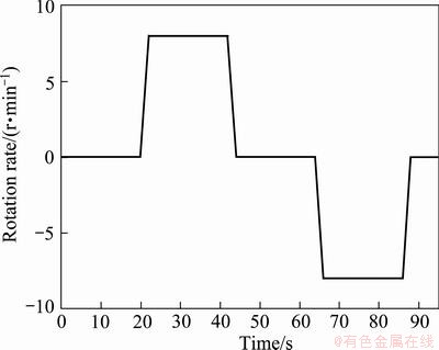
Fig. 1 Schematic diagram of ACRT rotation sequence
To study the interface and the distribution of twins, wafers were cut along the growth direction and perpendicular to the growth direction near the interface, respectively. The wafers were mechanically polished with MgO powder and colloidal silica gel subsequently in turn for IR microscope and laser confocal microscope analysis.
Images of Te inclusions and growth interface were evaluated using an IR transmission microscopy equipped with an electrophysics MICRONVIEWER 7290A CCD camera in the resolution of 1.0 ��m and Navitar Zoom 6000 zoom lens as well as PIXCI SV5 video capture. A Lasertec VL2000DX-SVF17SP-RM white light laser scanning confocal microscope (LSCM) was also employed to characterize the morphology of growth interface and Te inclusions nearby. The LSCM system was equipped with a SVF-IM3 microscope and a TOS10 dry objective lens.
3 Results and discussion
After the crystal growth, CMT ingot with diameter of 30 mm and length of 130 mm was obtained. A thin silver-like layer, considered as Te layer, was found covering on the surface of the ingot. After polishing with sandpaper, the smooth ingot as shown in Fig. 2(a) was obtained. Slice cut along the growth direction is shown in Fig. 2(b), which demonstrates that the entire ingot can be divided into three parts, i.e., the single CMT crystal in the tip part, the two phase region consisting of CMT and Te in the middle part, the extra Te enrichment region in the end part. The appearance of the three parts reflects the character of solution growth. As the growth process goes on, there will be great amount of residual solvent in the end of the ingot. The solution Bridgman method should be terminated after the growth of a length of the ingot with remaining a region of Te rich solution in the ingot end, which will be solidified into the mixture structure of CMT crystal and Te phase after the growth. In between them will be transient region. The length of CMT single crystal region is about 60 mm, less than half of the whole ingot. The middle part and the end part of the ingot are of dendrite structures.
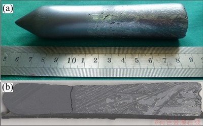
Fig. 2 Photograph of as-grown Cd0.9Mn0.1Te:In crystal ingot with 30 mm in diameter grown by Te solution technique (a); and longitudinal cross-section of whole ingot (b)
In the CMT crystal portion, as shown in Fig. 2(b), there are only two twins in the tip of CMT ingot and the following part up to the interface contains one single crystal. Twins in the ingot tip can be attributed to the sudden solidification of the super-cooled tip region at low temperature gradients [14,15]. A CMT wafer cut perpendicular to the growth direction is shown in Fig. 3(a) and the corresponding Cd0.9Mn0.1Te:In wafer from the ingot grown by vertical Bridgman technique is shown in Fig. 3(b). There are ten twins paralleled to each other in the wafer by vertical Bridgman technique, while only one twin is observed in the wafer by Te solution technique. It is known that the tendency to form twins in CMT increases with increasing Mn content [6], under the same Mn content, the twins are significantly reduced, even possibly completely removed by adopting Te solution technique.
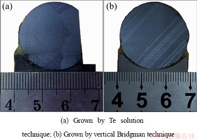
Fig. 3 Photographs of Cd0.9Mn0.1Te:In wafer cut perpendicular to growth direction of ingots
The CMT/Te interface region consisting of both CMT and Te phase was not as sharp as the interface of THM grown CZT ingot [9]. ACRT was introduced in the growth process, which had improved the growth interface shape and led to a high quality CMT crystal. A typical cross-sectional view of the growth interface is shown in Fig. 4(a). The black part was CMT formed in Te solvent and the bright part with dendrite structure was Te phase. It can be seen clearly that the growth interface was irregular and concave with dendrite-like growth fronts. The concave interface is not favorable for single crystalline growth, therefore, the grain boundary is observed in the corresponding wafer cut perpendicular to the growth direction near the interface.
The corresponding IR transmission image of the growth interface is shown in Fig. 4(b). The bright portion is grown CMT, while the black region is quenched Te rich solution. The interface is non-uniform, moreover, high concentration of Te inclusion exists in the vicinity of interface. From Fig. 4, some uncontrolled growth fronts grew more quickly than other fronts, which can cause two cases to observe. The first one was that when these uncontrolled growth fronts grew large, two growth fronts would touch in front of a Te solvent as a block; the second one was that a fast grown growth front grew toward back to growth interface and formed a so-called ��back-growth��. At last, in both cases, a small region of Te solvent was surrounded by these growth fronts and the movement of Te solvent was terminated, thus, high concentration of Te inclusion is observed in CMT crystal. ROY et al [9] and WANG et al [16,17] got similar results for THM grown CZT ingots. Hence, the concentration and size of Te inclusions in CMT crystals are significantly sensitive to the shape and the stability of the growth interface. The irregular and non-uniform grown front will cause high Te inclusion concentrating in the vicinity of the grown interface, which can be deduced that Te inclusions in CMT single crystal zone would possess different shapes and voids. By optimizing the growth parameters to control the shape and stability of the growth interface, solution technique can reduce the concentration of Te inclusions in CMT crystals.
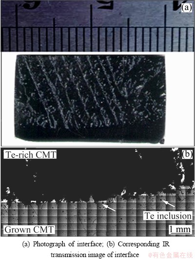
Fig. 4 Cross-sections of growth interface grown by Te solution technique
Unlike the Te inclusions in CMT crystal region, Te phase in Te-rich CMT region close to the growth interface was distributed non-uniformly and randomly with different shapes and sizes, which can be attributed to rapid cooling down below the melting point of Te at the end of the growth process. Te solvent and CMT melt could deposit randomly near the interface and in the Te-rich CMT region. The surface of Te solidified in Te-rich CMT region near the interface was not smooth, and sometimes the holes can be observed in the Te inclusions, which can be seen clearly from the morphology of the growth interface by laser confocal microscope, as shown in Fig. 5.
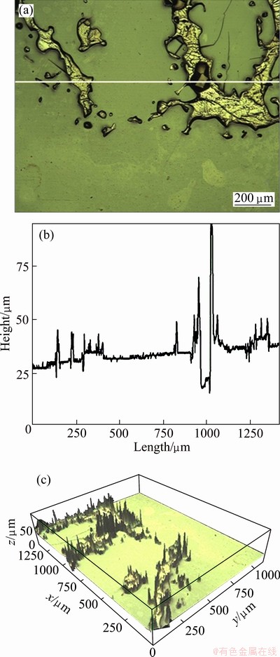
Fig. 5 Morphology of growth interface by laser confocal microscope (a), height profile graph of interface (b) and 3D version of growth interface (c)
From Fig. 5, it can be seen that the bottom smooth part is CMT structure and the top rough part is Te structure. Voids and polycrystalline Te phase with many kinds of shapes are shown in Fig. 5(a). The height profile along the white line on the LSCM image is provided in Fig. 5(b), which shows the differences in height of the surface topography. The diameter and depth of the voids were 47.5 ��m and 46.8 ��m, respectively, which indicates that the shape of the voids is closed to sphere with minimum surface energy. The voids in Te particles can be ascribed to the volume shrinking caused by the increase of density during cooling. Figure 5(c) provides a three-dimension representation of height data of LSCM image for showing the surface topography. A three-dimensional stack of images is digitally processed by assembling a series of single images (optical slices) taken along the vertical axis [18,19]. Te phase near the interface had different heights and voids, which can be seen clearly from the 3D image. In order to avoid any random deposition of Te particles at the interface and Te inclusions in the CMT crystal, a smooth growth interface is required by optimizing the growth parameters.
4 Conclusions
1) Cd0.9Mn0.1Te:In ingots of up to 30 mm in diameter and 60 mm in length are grown from Te solution vertical Bridgman method using Te as the solvent.
2) Te solution vertical Bridgman method with ACRT technique can effectively reduce the twins in CMT crystal.
3) Both macroscopic and microscopic morphology of growth interface are investigated by a quenching technique. The results indicate that the non-uniform and irregular interface can lead to polycrystalline and higher Te inclusion density.
4) The laser confocal microscope images reveal that the Te phases are deposited randomly in the Te-rich CMT region with irregular shapes and voids.
References
[1] MYCIELSKI A, BURGER A, SOWINSKA M, GROZA M, SZADKOWSKI A, WOJNAR P, WITKOWSKA B, KALISZEK W, SIFFERT P. Is the (Cd, Mn)Te crystal a prospective material for X-ray and ��-ray detectors? [J]. Physica Status Solidi C, 2(5): 1578-1585.
[2] HOSSAIN A, CUI Yong-gang, BOLLTNIKOV A E, CAMARDA G S, YANG Ge, KOCHANOWSKA D, WITKOWSKA-BARAN M, MYCIELSKI A, JAMES R B. Vanadium-doped cadmium manganese telluride (Cd1-xMnxTe) crystals as X- and gamma-ray [J]. Journal of Electronic Materials, 2009, 38(8): 1593-1599.
[3] ZHANG Ji-jun, JIE Wan-qi, WANG Ling-hang, LUAN Li-jun. Twins in CdMnTe single crystals grown by Bridgman method [J]. Crystal Research and Technology, 2010, 45(1): 7-12.
[4] TRIBOULET R, HEURTEL A, RIOUX J. Twin-free (Cd, Mn)Te substrates [J]. Journal of Crystal Growth, 1990, 101(1-4): 131-134.
[5] NAKOS J S. Effects of crystal growth process parameters on the microstructural optical and electrical properties of CdTe and CdMnTe [D]. Boston: Department of Materials Science and Engineering, Massachusetts Institute of Technology, 1988: 1-237.
[6] PERKOWITZ S, SUDHARSANAN R, WROBEL J M, CLAYMAN B P, BECLE P. Effective charge and ionicity in Cd1-xMnxTe [J]. Physical Review B, 1988, 38(8): 5565-5567.
[7] BABALOLA O S, BOLOTNIKOV A E, GROZA M, HOSSAIN A, EGARIEVWE S, JAMES R B, BURGER A. Study of Te inclusions in CdMnTe crystals for nuclear detector applications [J]. Journal of Crystal Growth, 2009, 311(14): 3702-3707.
[8] SAHOO D, SRIKANTIAH R V. Solution growth of cadmium telluride [J]. Bulletin of Materials Science, 1996, 19: 483-493.
[9] ROY U N, WEILER S, STEIN J. Growth and interface study of 2 in diameter CdZnTe by THM technique [J]. Journal of Crystal Growth, 2010, 312(19): 2840-2845.
[10] JIE Wan-qi. Principle and technology of crystal growth [M]. Beijing: Science Press, 2010: 493-494. (in Chinese)
[11] LIU Yong-cai, DOST S, LENT B, REDDEN R F. A three-dimensional numerical simulation model for the growth of CdTe single crystals by the traveling heater method under magnetic field [J]. Journal of Crystal Growth, 2003, 254(3-4): 285-297.
[12] ZHANG Ke-cong, ZHANG Le-hui. Crystal growth science and technology [M]. Beijing: Science press, 1997: 390-393. (in Chinese)
[13] ZHENG Xin, DU Yuan-yuan, WANG Tao, JIE Wan-qi, QI Yang, LUAN Li-jun. Study on Cd0.9Mn0.1Te growth behavior by Te solvent-bridgman method [J]. Journal of Synthetic Crystals, 2012, 41(2): 306-311.
[14] PFEIFFER M, MUHLBERG M. Interface shape observation and calculation in crystal growth of CdTe by the vertical Bridgman method [J]. Journal of Crystal Growth, 1992, 118(3-4): 269-276.
[15] MUHLBERG M, RUDOLPH P, GENZEL C, WERMKE B, BECKER U. Crystalline and chemical quality of CdTe and Cd1-xZnxTe grown by the Bridgman method in low temperature gradients [J]. Journal of Crystal Growth, 1990, 101(1-4): 275-280.
[16] WANG Yue, KUDO K, INATOMI Y, JI Rong-bin, MOTEGI T. Growth and structure of CdZnTe crystal from Te solution with THM technique under static magnetic field [J]. Journal of Crystal Growth, 2005, 275(1-2): e1551-e1556.
[17] WANG Yue, KUDO K, INATOMI Y, JI Rong-bin, MOTEGI T. Growth interface of CdZnTe grown from Te solution with THM technique under static magnetic field [J]. Journal of Crystal Growth, 2005, 284(3-4): 406-411.
[18] FAUCHEU J, WOOD K A, SUNG L P, MARTIN J W. Relating gloss loss to topographical features of a PVDF coating [J]. Journal of Coatings Technology and Research, 2006, 3(1): 29-39.
[19] SUNG L P, JASMIN J, GU Xiao-hong, NGUYEN T, MARTIN J W. Use of laser scanning confocal microscopy for characterizing changes in film thickness and local surface morphology of UV-Exposed polymer coatings [J]. Journal of Coatings Technology and Research, 2004, 1(4): 267-276.
ACRT-Te��ҺBridgman��������In����CdMnTe�����о�
��1��������1��֣ �1���� ��1��������2���� ��1
1. ������ҵ��ѧ ����ѧԺ ���̼��������ص�ʵ���ң����� 710072��
2. �Ϻ���ͨ��ѧ ����ϵ �˹��ṹ�����ӵ��ؽ������ص�ʵ���ң��Ϻ� 200240
ժ Ҫ������ACRT-Te��Һ��ֱ�����������ɹ��Ʊ���ֱ��Ϊ30 mm������Ϊ60 mm��CdMnTe�������������ͨ����������������CdMnTe������Te��Һ��������CdMnTe�����е��Ͼ������١��������ڽϸߵ�Te�������ܶȣ�������������ʾ�����������������ò�Ȳ�����Ҳ������ͬʱ�����ü���۽�����Ҳ�۲쵽CdMnTe��Te���������ɳ����ĺ��п��IJ�������״Te�ࡣ������ú��ʵ��������յõ���Ϊƽֱ���������棬Te��Һ��ֱ����������������Ч����CdMnTe�����е��Ͼ���
�ؼ��ʣ���Һ����������ֱBridgman ����CdMnTe���Ͼ����������棻Te ������
(Edited by CHEN Ai-hua)
Foundation item: Projects (50872111, 50902113, 61274081) supported by the National Natural Science Foundation of China; Project (2011CB610406) supported by the National Basic Research Program of China; Project (B08040) supported by the 111 Project of China; Project (JC20100228) supported by Foundation for Fundamental Research of Northwestern Polytechnical University (NPU), China; Project (SKLSP201012) supported by the Research Fund of the State Key Laboratory of Solidification Processing (NPU), China
Corresponding author: DU Yuan-yuan, Tel: +86-29-88486065; Fax: +86-29-88495414; E-mail: duyy1983@gmail.com

