
Domain wall structure transition during magnetization reversal process in magnetic nanowires
HAN Nian-mei(韩念梅), GUO Guang-hua(郭光华), ZHANG Guang-fu(张光富),
SONG Wen-bing(宋文斌), MEN Gao-fu(门高夫)
School of Physics Science and Technology, Central South University, Changsha 410083, China
Received 4 December 2006; accepted 2 April 2007
Abstract:The analytical micromagnetics and numerical simulations were used to investigate the domain wall structure during the magnetization reversal in nanowires. Micromagnetic analysis shows that the domain wall structure is mainly determined by the competition between the demagnetization energy and exchange energy. The wall with vortex magnetization structure in cross-section is energetically more favorable for wires with large diameter. With the reduction of diameter the exchange energy increases. At a critical diameter the vortex structure can not be sustained and the transition from vortex wall to transverse wall occurs. The critical diameters for this transition are about 40 nm for Ni wire and 20 nm for Fe wire, respectively. A series of micromagnetic simulations on the cone-shaped wire confirm the analytical results. The simulations also show that during the reversal process the vortex domain wall moves much faster than the transverse one.
Key words: magnetic nanowire; magnetization reversal; domain wall structure; micromagnetics
1 Introduction
The magnetization reversal of magnetic nanowires has been studied for a long time and has attracted much attention especially in recent years due to their potential use as high-density perpendicular recording media and spintronic sensing devices[1-2]. The magnetization reversal processes for infinite cylinder were studied theoretically very early[3-4]. Two reversal mechanisms were suggested, namely coherent rotation mode and curling mode. However, numerous micromagnetic simulations on soft magnetic nanowires show that the magnetization reversal in wires with finite length is significantly different from the reversal in infinite cylinder. It was reported that soft magnetic nanowires can switch in two different reversal modes, known as the transverse wall mode and the vortex wall mode[5-8], depending on their diameter. For thin wires reversal process occurs in transverse wall mode. As to wires with large diameter reversal takes place with vortex wall mode. In both modes the wires switch by means of nucleation at the end of wires and subsequent propagation. The difference of these two modes consists in the magnetization configuration in cross-section of wall. The configuration in cross-section for transverse domain wall is uniform, while the vortex domain wall has vortex distribution. The transition diameter between the two reversal modes is about 40 nm for Ni wires[9], which is very close to the critical diameter 41 nm between the coherent rotation mode and the curling mode for infinite cylinder. WERNSDORFER et al[10] and WEGROWE et al[11] confirmed this nucleation reversal mechanism. At present, there are few studies on the domain wall structure in magnetic nanowire and the transition between the transverse domain wall and the vortex domain wall is still not clear. In this study, the structures of transverse and vortex domain wall were investigated by micromagnetic analysis. Micromagnetic simulations based on the finite-difference method were used to verify the analytic results.
2 Micromagnetic analysis
According to the micromagnetic simulation studies [5-6], the magnetization reversal processes in soft magnetic nanowires occur in transverse wall mode or vortex wall mode depending on the wire’s diameter. The schematic diagrams of domain wall and the magnetiza- tion distributions in cross-section are depicted in Fig.1.
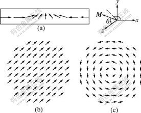
Fig.1 Schematic diagrams of domain wall of soft magnetic wire (a), magnetization distributions in cross-section for transverse domain wall (b) and for vortex domain wall (c)
For soft magnetic nanowire, if the magneto- crystalline anisotropic energy is neglected[12], the domain wall energy mainly comprises the demagnetiza- tion energy and exchange energy. The competition between these two energies decides the domain wall structure. The domain wall energy can be written in polar coordinate as follows:
 (1)
(1)
where θ and  are the polar angle and the azimuthal angle of magnetization, respectively (Fig.1(a)). The first term is the exchange energy. The second one denotes the demagnetization energy.
For transverse domain wall, as the magnetization distribution in cross-section is uniform (displayed in Fig.1(b)), the magnetization configuration is one- dimensional. In this case, θ=θ(z) and is a constant. According to Ref.[13], the demagnetization energy density εm can be written approximately as follows:
 (2)
(2)
where Nr is demagnetization factor; Mx and My are the magnetization components perpendicular to the long axis of wire. Therefore, the transverse wall energy is
 (3)
(3)
For vortex domain wall structure, the magnetization configuration in cross-section has vortex form (Fig.1(c)). In consequence, the demagnetization energy is zero. But the exchange interaction in cross-section will appear (the second term of exchange interaction in Eqn.(1)), which can be approximately written as πpAln(d/2a)sin2θ per unit length of wire[14], where a is the distance between
the two nearest atoms, and p is equal to  (or
(or )
)
for the face-centered cubic structure (or body-centered cubic structure). Hence, the energy of vortex domain wall can be expressed as
 (4)
(4)
The variation of the transverse wall energy (Eqn.(3)) and the vortex wall energy (Eqn.(4)) leads to the well-known Eular equation:
 (5)
(5)
where  and K=
 for transverse
wall and vortex wall, respectively.
By solving Eqn.(5) with the following boundary conditions: θ=0 for z=+∞, θ=π for z=-∞ and dθ/dz=0 for z=±∞, we can get the distribution of θ as a function of z. Putting θ(z) into Eqns.(3) and (4), the domain wall energies corresponding to the transverse wall and the vortex wall can be obtained as follows:
 (6)
(6)
The transition from the transverse wall mode to the vortex wall mode occurs at the critical diameter where the energies of transverse wall and vortex wall are equal.
For Ni nanowire, if the magnetic parameters are taken as Ms, Ni=4.9×10⁵ A/m and ANi= 9×10-12 J/m[15], according to Eqn.(6), the critical transition diameter is equal to 40 nm. For Fe nanowire, the diameter will be 20 nm with Ms, Fe=1.7×10⁶ A/m and AFe= 2.1×10⁻¹¹ J/m[16].
3 Micromagnetic simulations
Micromagnetic simulations based on the finite-difference method were used to prove the above analytic results. Micromagnetics is a continuum theory for the description of magnetization configuration in ferromagnetic material. The equilibrium magnetization distributions were characterized by local minima of the total Gibbs free energy. The actual processional motion of individual magnetic moments due to all internal and external fields follows the Landau-Lifshitz-Gilbert equation, which has the following form:

(7)
where γ is the gyromagnetic ratio; α is the Gilbert damping constant; Heff denotes the effective field acting on the magnetic moment, which can be written as
Heff= (8)
(8)
In order to study the diameter-dependent transition between the transverse wall mode and the vortex wall mode, the magnetization reversal processes of cone- shaped Ni and Fe wires with linearly varying diameter were investigated as done in Ref.[9]. The length of wire is 1 200 nm, and the diameter is 50 nm at one end and 20 nm at the other. The numerical simulations were carried out by using the object-oriented micromagnetic framework code[17]. The discretization cell is taken to be 2 nm, and a large Gilbert damping constant α=0.5 is used in order to speed up the computations.
When a reversed field of 300 mT is applied to the Ni wire, the reversal begins as the nucleation of a reversed domain with a vortex domain wall at the end with a larger diameter. Then the vortex wall propagates along the wire until it reaches a region with a critical diameter, where the wire becomes too thin to sustain the vortex structure. The vortex wall then converts into the transverse domain wall. The transition can be clearly seen in Fig.2, where the onset of the typical oscillations in the perpendicular components of the magnetization clearly indicates the conversion from the vortex wall mode into the transverse wall mode. Owing to the difference of α, the critical time tc is different from Ref.[9], but it doesn’t affect the magnetization reversal of the nanowires. As the magnetization distribution of the vortex domain wall in cross-section is vortex, perpendicular components of the magnetization are zero. While the magnetization configuration of transverse domain wall in cross-section is uniform, during the reversal process magnetization performs a characteristic spiraling motion as the torque exerted on the magnetic moments is along the axial direction. This leads to the oscillation of Mx and My with time. The transition between the two reversal modes occurs at about 40 nm for Ni wire and about 20 nm for Fe wire, which are in full agreement with the analytical results obtained by micromagnetic analysis.
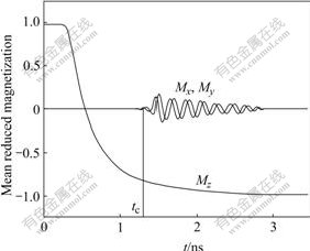
Fig.2 Average magnetization components as functions of time during magnetization reversal in Ni nanowire (Mz represents component parallel to wire axis; Mx and My represent components perpendicular to wire axis)
From Fig.2 it can been seen that the slope of magnetization along the wire during the reversal process in vortex wall mode is much larger than that in transverse wall mode, which means that the vortex domain wall moves much faster than the transverse domain wall. The simulation results are consistent with those in Refs.[8-9].
4 Conclusions
1) The domain wall structure is mainly determined by the competition between the demagnetization energy and exchange energy. For wires with large diameter, the domain wall with vortex magnetization configuration in cross-section has low wall energy. As the diameter decreases, the exchange energy increases. At a critical diameter the vortex structure is energetically unfavorable and the transition from vortex wall to transverse wall occurs. The critical diameters for this transition are 40 nm for Ni wire and 20 nm for Fe wire, respectively.
2) When the vortex domain wall, which is formed at one end of wire with larger diameter at the beginning of reversal, reaches a region with a critical diameter, the vortex structure can not be sustained, and the transition between the vortex wall and transverse wall occurs. Simulations also show that during the reversal process the vortex domain wall moves much faster than the transverse domain wall.
References
[1] SELLMYER D J, ZHENG M, SKOMSKI R. Magnetism of Fe, Co and Ni nanowires in self-assembled arrays [J]. J Phys: Condens Matter, 2001, 13(25): R433-R460.
[2] KR?LL M, BLAU W J. Magnetic properties of ferromagnetic nanowires embedded in nanoporous alumina membranes [J]. J Magn Magn Mater, 2002, 249(1/2): 241-245.
[3] AHARONI A, SHTRIKMAN S. Magnetization curve of the infinite cylinder [J]. Phys Rev, 1958, 109(5): 1522-1528.
[4] FREI E H, SHTRIKMAN S, TREVES D. Critical size and nucleation field of ideal ferromagnetic particles [J]. Phys Rev, 1957, 106(3): 446-455.
[5] HINZKE D, NOWAK U. Magnetization switching in nanowires: Monte Carlo study with fast Fourier transformation for dipolar fields [J]. J Magn Magn Mater, 2000, 221(3): 365-372.
[6] ZHANG La-mei, GUO Guang-hua, LIU Zheng-fang. Micromagnetic simulation of magnetization reversal mechanism in magnetic nanowires [J]. The Chinese Journal of Nonferrous Metals, 2005, 15(5): 787-792. (in Chinese)
[7] HERTEL R. Micromagnetic simulations of magnetostatically coupled nickel nanowires [J]. J Appl Phys, 2001, 90(11): 5752-5758.
[8] FORSTER H, SCHREFL T, SUESS D, SCHOLZ W, TSIANTOS V, DITTRICH R, FIDLER J. Domain wall motion in nanowires using moving grids [J]. J Appl Phys, 2002, 91(10): 6914-6919.
[9] HERTEL R, KIRSCHNER J. Magnetization reversal dynamics in nickel nanowires [J]. Physica B, 2004(343): 206-210.
[10] WERNSDORFER W, DOUDIN B, MAILLY D, HASSELBACH K, BENOIT A, MEIER J, ANSERMET J P, BARBARA B. Nucleation of magnetization reversal in individual nanosized nickel wires [J]. Phys Rev Lett, 1996, 77(9): 1873-1876.
[11] WEGROWE J E, KELLY D, FRANCK A, GILBERT S E, ANSERMET J P. Magnetoresistance of Ferromagnetic Nanowires [J]. Phys Rev Lett, 1999, 82(18): 3681-3684.
[12] SKOMSKI R, ZENG H, SELLNYER D J. Incoherent magnetization reversal in nanowires [J] . J Magn Magn Mater, 2002, 249: 175-180.
[13] BRAUN H B. Nucleation in ferromagnetic nanowires―magneto- statics and topology [J]. J Appl Phys, 1999, 85(8): 6172-6174.
[14] ZHONG Wen-ding. Ferromagnetics [M]. Beijing: Science Press, 1998. (in Chinese)
[15] WHITTENBURGA S L, DAO N, ROSS C A. Micromagnetic studies of hysteresis in nickel pillars [J]. Physica B, 2001, 306(1): 44-46.
[16] L?PEZ-UR?AS F, TORRES-HEREDIA J J, MU?OZ-SANDOVAL E. Magnetization patterns simulations of Fe, Ni, Co, and permalloy individual nanomagnets [J]. J Magn Magn Mater, 2005, 294(2): e7-e12.
[17] DONAHUE M J, PORTER D G. OOMMF User’s Guide, Release 1.2a [EB/OL]. http://math.nist.gov/oommf/, 2002-10-30.
Foundation item: Project(60571043) supported by the National Natural Science Foundation of China; Project(04JJ3078) supported by the Natural Science Foundation of Hunan Province, China
Corresponding author: GUO Guang-hua; Tel: +86-731-8836443; E-mail: guogh@mail.csu.edu.cn
(Edited by LI Xiang-qun)

