Trans. Nonferrous Met. Soc. China 25(2015) 3716-3722
Friction and wear behaviors of TiCN coating based on electrical discharge coating
Zhao-yubo ZENG, Hou-qun XIAO, Xiao-hua JIE, Yan-mei ZHANG
School of Materials and Energy, Guangdong University of Technology, Guangzhou 510006, China
Received 22 September 2014; accepted 5 May 2015
Abstract: Titanium carbonitride (TiCN) coating was prepared on 45# carbon steel by electrical discharge coating (EDC), and the compositions, morphology and microstructure of the coating were studied. In addition, its friction and wear behaviors relative to the physical vapor deposition (PVD) TiN coating were investigated. The results show that the TiCN coating features a thickness of 15 μm with a primary phase of TiC0.3N0.7. The wear rates of the two coatings have no clear distinction at low applied loads. However, severe abrasive wear appears in the PVD TiN coating when the applied load exceeds 30 N, while the TiCN coating features better wear resistance. The abrasive wear with coating peelings is found to be the predominant wear mechanism at high applied loads.
Key words: electrical discharge coating; titanium carbonitride; mechanical properties; friction and wear
1 Introduction
In the past several decades, cermet coatings have proven to be most effective in increasing the durability of tools [1,2]. There are many fabrication techniques for cermet coatings, such as physical vapor deposition (PVD) [3], chemical vapor deposition (CVD) [4] and laser cladding [5]. Among those coatings, TiC and TiN coatings have been extensively used as wear resistance layers based on their high hardness and excellent tribological performance [6]. As a solid solution of TiC and TiN, titanium carbonitride (TiCN) has attracted more attention in industrial applications due to its excellent mechanical properties of high hardness, low friction coefficient and corrosion resistance [7]. However, conventional CVD and PVD techniques need severe conditions and expensive apparatus [8]. For instance, the PVD and CVD hard coatings are normally processed at high temperatures (500-1000 °C) and possess unsatisfactory thin coating thickness (2-5 μm) as well as low adhesive strength. Furthermore, some poisonous precursors have been used in the CVD technique [9,10].
Electrical discharge coating (EDC) is a revolutionary technique, by which various cermet coatings can be created with an electrical discharge machining (EDM) tool using particular electrodes and dielectric fluid [11]. Compared with CVD and PVD, the superiority of EDC is to prepare hard coatings at room temperature under simple conditions, which are characterized with adjustable thickness and a metallurgical bonding to the substrate. Binary hard coatings such as titanium carbide (TiC) [12] and titanium nitride (TiN) [13] have been created via EDC. Using multi-layer electrodes (MLE) composed of titanium and graphite layers, HWANG et al [14] successfully formed a titanium carbide (TiC) layer on the surface of a nickel workpiece, the effects of Gr layer on the MLE were discussed as well, and the results were compared with coatings prepared by conventional bulk electrode. By using a fluid dielectric oil which was mixed with titanium powder, JANMANEE and MUTTAMARA [15] coated a titanium layer with increased microhardness and few micro-cracks onto a tungsten carbide surface, and discussed the parameters affecting the surface coating.
However, all the studies focus on the fabrication of EDC TiC coating, and few works deal with EDC ternary cermet coatings [16]. Till now, there has been no investigation on the preparation of TiCN coating by EDC, especially on its friction and wear behaviors. In order to investigate the tribological prosperities of TiCN coatings based on EDC, the wear tests sliding against Si3N4 balls using the ball-on-disc tribometer at different applied loads were carried out. In addition, the comparative wear characteristics and wear mechanisms between the EDC TiCN coating and PVD TiN coating were investigated.
2 Experimental
2.1 Coating preparation
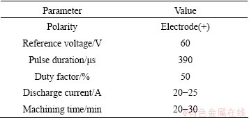
The workpiece material was 45# steel (carbon steel, Chinese standard GB699-88, with dimensions of 20 mm × 20 mm × 5 mm). Before deposition, the substrates were polished to mirror surface and then ultrasonically cleaned in acetone and ethanol three times. The nitrogenous medium consisted of 900 mL ethanolamine (NH2―CH2―CH2―OH) (Tianjin Fuyu Chemical Co., Ltd.) and 100 mL deionized water. 17.5 g potassium chloride (Sinopharm Chemical Reagent Co., Ltd.) was also added to improve the fluidity. The investigated TiCN coatings were prepared by a JXD7125 accurate shaping electrical discharge machining tool. The cuboid smelted titanium was used as the tool electrode. The preparation system includes the tool electrode and substrate, and the ethanolamine solution was placed into a closed container. The optimized EDC conditions are summarized in Table 1.
Table 1 Deposition conditions for EDC process
In contrast, conventional PVD TiN coatings were prepared by a direct current magnetron sputtering (MS) system with a single titanium target (99.95% purity). The substrate was the same as that of the EDC process. The distance between the target and substrate was held at 85 mm, and the target current was 0.3 A. The total flow rate of N2 and Ar gas was set at 30 cm3/min to keep the work pressure at 0.3 Pa.
2.2 Characterization and wear tests of coatings
X-ray diffraction (XRD) was performed by an X-ray diffractometer with Cu Kα radiation (D/max-γ A10, Rigaku, Japan). The surface and cross-sectional morphologies of coatings were examined by an S-3400N-II scanning electron microscope (SEM) and the microstructure was examined using a transmission electron microscope (TEM) (JEM-2100, JEOL, Japan). The microhardness was tested by an AKASHI MVK-H3 Vickers hardness tester with an indenting load of 1.96 N. Friction and wear tests were performed on a CFT-I tribometer developed by Lanzhou Institute of Chemical Physics, China, and the ball-on-disc configuration was used. In this test, Si3N4 balls with a diameter of 4 mm and hardness of HV 1800 were chosen as the counterpart, and the reciprocating friction was applied. All wear tests were performed under dry sliding conditions in air at 20-26 °C with a relative humidity of 40%-50%. The profiles of the wear tracks were observed by a Dektak150 profilometer. All the wear samples were cleaned with acetone and then weighed with an accuracy of ±0.1 mg before and after every sliding wear tests. The wear mass loss was then identified by subtracting the remained mass from the original mass. The wear testing parameters are summarized in Table 2.
Table 2 Tribological test parameters.

3 Results and discussion
3.1 Microstructure and phase of TiCN coatings
The XRD patterns of two coatings are shown in Fig. 1. It reveals that the as-prepared TiCN coating consists mainly of TiC0.3N0.7 phase, and few Fe3N and Ti2N phases are also identified. According to the characteristics of EDC process, activated Ti atoms from the electrode react with C and N atoms ionized by the dielectric medium, forming the TiCN coating on the surface of the substrate. Fe3C comes from the substrate, because the depth of investigation of XRD can reach dozens of micrometers. Ti2N, Fe3N and TiCN are the reaction products during the EDC processing [17]. As for the PVD TiN coating, because of its thin thickness, the small-angle diffraction method was applied. Thus, the substrate peak is not observed in the XRD pattern of TiN coating. In addition, it can be observed that the growth of PVD TiN grains results in a strong (111) prefer orientation.

Fig. 1 XRD patterns of TiCN coating (a) and TiN coating (b)
Figure 2 shows the microstructure of the EDC TiCN coating. The TEM bright image with the corresponding selected-area electron diffraction (SAED) pattern of TiCN coating is shown in Fig. 2(a). It is noticed that the surface microstructure of the coating is composed of randomly oriented grains, and the SAED pattern consists of discontinuous diffraction rings, confirming the formation of fine grains. The surface morphology of TiCN coating presents a pattern of ocean wave, and it is identical to the previous research [15]. As it resembles the process of EDM, a single pulsed discharge by EDC would create a crater on the surface of substrate, and then the crater would be rapidly solidified by the surrounding working fluid, and a small amount of TiCN deposits simultaneously. Therefore, the craters overlap each other after a large quantity of pulsed discharge, forming a fluctuant surface of the coating.

Fig. 2 TEM bright image and corresponding selected-area electron diffraction pattern (a), and SEM micrograph of surface morphology (b) of EDC TiCN coating
Figure 3 shows the cross-sectional SEM images of PVD TiN coating and EDC TiCN coating. As can be seen that the PVD TiN coating consists of typical columnar grains, and its thickness is only about 2 μm (Fig. 3(a)). However, the average thickness of TiCN coating is about 15 μm (Fig. 3(b)) and its surface is not as smooth as that of PVD TiN coating. Like laser cladding, a heat affected zone (HAZ) can be found between the coating and substrate.
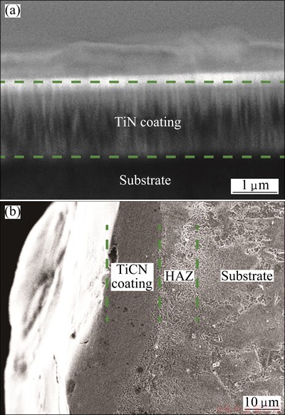
Fig. 3 Cross-sectional SEM images of TiN coating by PVD (a) and TiCN coating by EDC (b)
3.2 Microhardness analysis of coatings
Figure 4 shows the microhardness of two coatings with the depth increasing from the surface coating to the substrate. Although the hardness of the PVD TiN coating (the maximum value is HV0.2 1980) is a little higher than that of the TiCN coating (HV0.2 1780), the hardness gradient in the PVD TiN coated sample changes quickly. However, the hardness of the TiCN coating presents a graded distribution, and the hardness of HAZ at the interface still keeps at HV0.2 800. Moreover, the hardness of EDC TiCN coating reduces due to its microstructure of multi-phase.
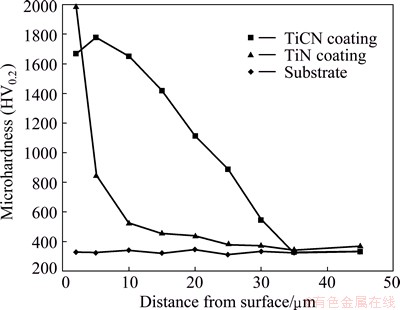
Fig. 4 Microhardness of coatings with depth increasing from surface coating to substrate
3.3 Wear behaviors
The wear behaviors of the coatings mainly depend on the microstructure, hardness and binding strength, which are usually measured in terms of friction coefficient and wear mass loss. Figure 5 shows the friction coefficients of two coatings and the substrate as functions of wear time under the load of 10 N. It can be seen that the average friction coefficient of the substrate is the highest, and the friction coefficient of TiCN coating decreases by 33.8% compared with that of the substrate. During the 30 min wear test, although the friction coefficient of the substrate reaches a relatively stable value after a short running-in stage, those of two coatings still experience a slowly increasing period during the initial stage of wear. In general, the friction is mainly caused by the dual roles of the mechanical interlock and molecular attraction of friction pairs. Due to the smooth surface of TiN coating, the micro-mechanical interlocking effect between the friction pairs is not so strong compared with that under the given load, and the friction coefficient is smaller than that of the substrate consequently. However, the surface of TiCN coating is composed of a large number of stacked craters, as shown in Fig. 2(b), and its surface hardness is high. It can be deduced that the actual contact area is a set of crater edges in the initial stage of wear, and the crater edges connected to each other just play a role as rolling balls, causing a lower friction coefficient. As the wear continues, the molecular attraction progressively increases, and the increased real contact area brings a tough wear. Therefore, the friction coefficient of two coatings gradually increases to a stable value ultimately.

Fig. 5 Friction coefficients of TiCN coating, TiN coating (PVD) and substrate as functions of wear time

Fig. 6 Wear mass loss of PVD TiN, EDC TiCN and substrate under different normal loads
The wear mass loss of the two coatings and substrate under different normal loads is shown in Fig. 6. It can be seen that the wear loss of substrate varies lineally with increasing the applied load. Although the wear loss of PVD TiN coating is the least under the loads of 10 and 20 N, it distinctly exceeds that of the TiCN coating when the applied load is over 30 N. The profiles of sectional wear tracks of these two coatings under the load of 30 N are shown in Fig. 7. It indicates that the maximal depth of the wear tracks of TiCN coating is slightly smaller than that of PVD TiN coating. This is consistent with the result of wear loss. In addition, TiCN coating possesses smoother wear tracks. The distinctive sectional morphologies of these coatings could be affected by different friction and wear behaviors.

Fig. 7 Sectional profiles of wear tracks on TiN (a) and TiCN (b) coatings
Figure 8 presents the wear surface morphologies of the two coatings under different applied loads. As exhibited in Fig. 8(a), some apparent and slight grooves can be seen on the wear surface of PVD TiN coating under the load of 10 N, which is in conformity with the mechanism of mild wear. When the applied load increases to 20 N (Fig. 8(b)), a large number of grooves which are parallel to the sliding direction on the wear surface can be observed. Serious delamination of coating and severe adhesion can be seen in the wear tracks of the PVD coating at 30 N (Fig. 8(c)), and the abrasion mechanism under high applied loads is the typical fatigue flake.
As the EDC TiCN coating is constituted by complex composition, its surface is not smooth as that of PVD TiN coating. As mentioned above, the hardness and friction coefficient are not identical compared with those of PVD TiN coating [18]. Due to the high surface hardness of PVD TiN coating, the tribological property of EDC TiCN coating is inferior to that of PVD TiN coating under low applied load. However, as the PVD TiN coating consists of columnar crystals, its mechanical properties are comparatively unstable. Therefore, with poor adhesion strength and obvious preferred orientation, it is easy to peel off when the applied load becomes higher. The peeled hard particles would act as abrasive particles between the friction pairs, which further results in serious wear and spalling. Combined with the thickness of PVD coating, it would be much easier to wear out during the reciprocating wear process. Moreover, it can be confirmed that the wear mass loss for TiN coating at 40 N may be the sum of wear loss for coating and substrate.
The wear tracks of TiCN coating by EDC are similar to those of PVD TiN coating under the load of 20 N (Fig. 8(d)), there exists slight rubbing without obvious plastic deformation. The mild wear is found to be the predominant mechanism under low applied loads. Nevertheless, some ploughed grooves and coating delamination appear at the load of 30 N (Fig. 8(e)), and the width and depth of the wear scars increase. Under the circumstances, the coating debris would serve as abrasive particles between the friction pairs, causing relatively serious abrasive wear. However, the amount and dimension of the debris reduce greatly compared with those of PVD TiN coating, and the hardness is lower. Accordingly, similar situation of PVD TiN coating at 30 N does not appear for EDC TiCN coating. As the applied load increases to 40 N, some more severe parallel ploughed grooves and coating peeling can be seen (Fig. 8(f)). It can be confirmed that the abrasive wear and delamination wear are the predominant mechanisms at high loads.

Fig. 8 SEM morphologies of wear tracks for PVD TiN coatings at 10 N (a), 20 N (b), 30 N (c), and for TiCN coatings at 20 N (d), 30 N (e) and 40 N (f)
It is known that the ternary coating generally has the superior performance than the binary one. Moreover, TiCN coating has the advantages of TiN and TiC coatings simultaneously. LACKNER et al [18] showed that the C element can maintain the ideal properties of TiN, such as elevated hardness, good plasticity and reduced friction coefficient. Furthermore, the wear behaviors of coatings are highly correlated with their microstructures, the difference in microstructures effects directly to the hardness, adhesion, and mechanical properties. The hardness of the as-prepared TiCN coating reduces gradually from the top surface to the substrate, and there exists a metallurgical combination and a HAZ with a certain thickness at the interface. The existence of HAZ avoids the generation of the so-called “shell effect”, which is defined as soft inside and hard outside of the coating, playing a role to support the hardness of coating. Given the fine-grain microstructure and high adhesion strength, it is not easy to generate coating delamination at high applied loads. However, as for the “shell effect” of the PVD coating, its wear behaviors are not acceptable in the case of high applied loads. Therefore, the wear performance of the EDC TiCN coating features better.
4 Conclusions
1) TiCN cermet coating was successfully deposited on the surface of carbon steel based on EDC using an inclusive medium of carbon and nitrogen. The coating possesses a microhardness of HV 1780 and a thickness of 15 μm.
2) The friction coefficient of EDC TiCN coating decreases 33.8% compared with that of the substrate, and when the applied load exceeds 30 N, the wear mass loss of TiCN coating is less than that of PVD TiN coating. As a result of its satisfactory microstructure, the wear resistance is better.
3) The wear tracks of TiCN cermet coating exhibit massive parallel slight grooves at low applied loads. Mild wear is found to be the predominant mechanism at low applied loads. Some coating peelings and grooves appear when the applied load exceeds 30 N. Abrasive wear and delamination wear are found to be the predominant wear mechanism at high normal loads.
References
[1] KONYASHIN I Y. Wear-resistant coatings for cermet cutting tools [J]. Surface and Coatings Technology, 1995, 71(3): 284-291.
[2] SIOW P C, GHANI J A, GHAZALI M J, JAAFAR T R, SELAMAT M A, HARON C H C. Characterization of TiCN and TiCN/ZrN coatings for cutting tool application [J]. Ceramics International, 2013, 39(2): 1293-1298.
[3] LEE J K, YANG G S. Preparation of TiAlN/ZrN and TiCrN/ZrN multilayers by RF magnetron sputtering [J]. Transactions of Nonferrous Metals Society of China, 2009, 19(4): 795-799.
[4] ZHANG J, XUE Q, LI S. Microstructure and corrosion behavior of TiC/Ti(CN)/TiN multilayer CVD coatings on high strength steels [J]. Applied Surface Science, 2013, 280: 626-631.
[5] YANG Y, GUO N, LI J. Synthesizing, microstructure and microhardness distribution of Ti-Si-C-N/TiCN composite coating on Ti-6Al-4V by laser cladding [J]. Surface and Coatings Technology, 2013, 219(12): 1-7.
[6] AZADI M, ROUHAGHDAM A S, AHANGARANI S, MOFIDI H. Mechanical behavior of TiN/TiC multilayer coatings fabricated by plasma assisted chemical vapor deposition on AISI H13 hot work tool steel [J]. Surface and Coatings Technology, 2014, 245(5): 156-166.
[7] CARDINAL S, MALCHERE A, GARNIER V, FANTOZZI G. Microstructure and mechanical properties of TiC-TiN based cermets for tools application [J]. International Journal of Refractory Metals and Hard Materials, 2009, 27(3): 521-527.
[8] YANG J, CHEN K, WANG S, XIAO D, ZHU C. Characteristics and performance of Ti(C, N) coatings synthesized by magnetron sputtering technique [J]. Journal of Alloys and Compounds, 2009, 471(1): 162-165.
[9] AJIKUMAR P, KAMRUDDIN M, KALAVATHI S, BALAMURUGAN A, KATARIA S, SHANKAR P, TYAGI A. Synthesis, characterization and evaluation of titanium carbonitride surface layers with varying concentrations of carbon and nitrogen [J]. Ceramics International, 2012, 38(3): 2253-2259.
[10] KARLSSON L, HULTMAN L, JOHANSSON M, SUNDGREN J E, LJUNGCRANTZ H. Growth, microstructure, and mechanical properties of arc evaporated TiCxN1-x (0 ≤ x ≤1) films [J]. Surface and Coatings Technology, 2000, 126(1): 1-14.
[11] LEE S H, LI X. Study of the surface integrity of the machined workpiece in the EDM of tungsten carbide [J]. Journal of Materials Processing Technology, 2003, 139(1): 315-321.
[12] MORO T, MOHRI N, OTSUBO H, GOTO A, SAITO N. Study on the surface modification system with electrical discharge machine in the practical usage [J]. Journal of Materials Processing Technology, 2004, 149(1): 65-70.
[13] YAN B H, TSAI H C, HUANG F Y. The effect in EDM of a dielectric of a urea solution in water on modifying the surface of titanium [J]. International Journal of Machine Tools and Manufacture, 2005, 45(2): 194-200.
[14] HWANG Y L, KUO C L, HWANG S F. The coating of TiC layer on the surface of nickel by electric discharge coating (EDC) with a multi-layer electrode [J]. Journal of Materials Processing Technology, 2010, 210(4): 642-652.
[15] JANMANEE P, MUTTAMARA A. Surface modification of tungsten carbide by electrical discharge coating (EDC) using a titanium powder suspension [J]. Applied Surface Science, 2012, 258(19): 7255-7265.
[16] KUMAR S, SINGH R, SINGH T, SETHI B. Surface modification by electrical discharge machining: A review [J]. Journal of Materials Processing Technology, 2009, 209(8): 3675-3687.
[17] DAS S, KLOTZ M, KLOCKE F. EDM simulation: Finite element- based calculation of deformation, microstructure and residual stresses [J]. Journal of Materials Processing Technology, 2003, 142(2): 434-451.
[18] LACKNER J, WALDHAUSER W, EBNER R. Large-area high-rate pulsed laser deposition of smooth TiCxN1-x coatings at room temperature―Mechanical and tribological properties [J]. Surface and Coatings Technology, 2004, 188(2): 519-524.
液相脉冲放电涂层技术制备TiCN涂层的摩擦磨损性能
曾招余波,肖厚群,揭晓华,张艳梅
广东工业大学 材料与能源学院,广州 510006
摘 要:利用液相脉冲放电涂层技术(EDC)在45#钢基体上制备出TiCN金属陶瓷涂层,对涂层的成分、表界面形貌及显微组织进行分析和表征。研究涂层的常温滑动摩擦磨损行为,并与物理气相沉积(PVD)法所制备的TiN涂层进行对比。结果表明:所制备的TiCN涂层厚度约为15 μm,主要由TiC0.3N0.7相组成。在较小的载荷下,经由两种方法所制备的涂层的磨损量相差不大,但当载荷增加至30 N时,PVD方法所制备的TiN涂层出现严重的涂层剥落,而采用EDC方法所制备的TiCN涂层具有更好的耐磨擦磨损性能,磨粒磨损与剥层磨损是重载下涂层摩擦磨损的主要机制。
关键词:脉冲放电涂层技术;TiCN;力学性能;摩擦磨损
(Edited by Mu-lan QIN)
Foundation item: Project (51075075) supported by the National Natural Science Foundation of China
Corresponding author: Xiao-hua JIE; Tel: +86-20-39322576; Fax: +86-20-39322576; E-mail: jiexh@scnu.edu.cn
DOI: 10.1016/S1003-6326(15)64013-4

