J. Cent. South Univ. Technol. (2008) 15: 230-236
DOI: 10.1007/s11771-008-0044-5

Constitutive model of rock based on microstructures simulation
YE Zhou-yuan(叶洲元), HONG Liang(洪 亮), LIU Xi-ling(刘希灵), YIN Tu-bing(尹土兵)
(School of Resources and Safety Engineering, Central South University, Changsha 410083, China)
Abstract: The constitutive model of rock can be built by mechanics elements because there are many kinds of damages in rock under varied loads. It is resumed that rock contains many microstructures and a structure of Bingham. The microstructure consists of two embranchments that are the unit of a spring and a gliding slice in series and the unit of a spring and a cementation bar in series, the two units connect each other in parallel. These microstructures are arranged disorderly or in the order of a certain state. A certain distribution of microstructures represents one type of rock. Two kinds of rock’s constitutive relationship were deduced by using the model. One is the model in which many parallel microstructures and a structure of Bingham connect in series. And it is used to homogeneous rock. The other is the model in which many microstructures and a structure of Bingham connect in series. And it is used to the rock with much crack or microcrack in a certain direction. The two kinds of constitutive relationship were verified by the studied cases. The constitutive model of rock built by using mechanics elements is verified to be reasonable. Moreover, different types of rocks may be described with mechanics elements with different distributions.
Key words: constitutive model; microstructure; mechanics element; connecting type
1 Introduction
Rocks in nature had experienced long geologic tectonic and diagenetic action, which results in various kinds of damages and their properties differ from one another. In a macroscopic view, inside rock a lot of structural planes are formed, whose sizes and directions are different and whose characteristics are varied after being affected by geologic constitution and personal factor. In microscopic view, inner of rocks has various crystal surface, weakened surface, micro joints and fissures after accepting various effect, which makes the mechanical characteristics very complex. There are a lot of constitutive models on rock so far. A two-phase model of rock for brittle fracture was built due to uniaxial compression, considering rock to be a composite material consisting of hard grains and colloids[1]. The damage constitutive equations and damage evolution in three dimensional nonlinear state were derived based on damage structure and constitutive relation of common bedded composite rock[2]. Rock was considered a quasi-lamellar structure material and simplified to a simply supported beam, and then a catastrophe model was built by the catastrophic theory for underground chamber under laminated buckling under the condition of quasi-static pressure[3]. The discrete model was built for simulation of rock behavior[4]. A lot of models made up of mechanics elements were introduced in Ref.[5]. A new non-Newton damp component was put forward based on the rheological properties of rock and a new rheological multiple model combining the non-Newton damp component and conventional rheological models was built by DENG et al[6]. The new nonlinear viscous substance was used to improve the function of the classical Maxwell model and define a new visco-elasto-plastic constitutive model consisting of 5-components (VEP-5C model) in series with the improved Maxwell model[7]. In Ref.[8], spring, gliding slab and cementation bar were used to denote the solid’s mechanical behaviors, elasticity, plasticity and brittleness, respectively, and based on which a binary medium model was proposed. By the chain model consisting of springs, cementation bars and gliding slices, and homogenization method to combine the meso characteristics with the macro mechanical properties in the course of localized progressive damage, a localized progressive damage model was built up by ZHANG et al[9]. GRADY and KIPP[10] built a model, which has been found effective in describing the observed rate-dependent fracture phenomena from static to high strain-rate impulse loading. LI and GU[11] got the constitutive equation for rock undergoing impacting by curve fitting. CHANG and YANG[12] combined a spring-bonding-block system with
valanis-type elements, and showed it can characterize the stress relaxation phenomenon. In Ref.[13] a new catastrophe model was established for impact loading failure of a static loading rock system according to the catastrophe model for impact buckling of static loading structures and one dimension catastrophe model. LI et al[14-15] established the uniaxial and triaxial constitutive models of statically loaded rock under dynamic loading (coupled static-dynamic constitutive model) with intermediate strain rate, by way of combining statistic damage model and viscoelastic model. These constitutive models mainly emphasize on certain aspect of mechanical characteristics. So a constitutive model showing different aspects of mechanical characteristics was built in this work.
2 Constitutive model
Generally, rock mainly shows the mechanical behaviors including elasticity, viscosity, plasticity and brittleness undergoing varied loads. There are four mechanics elements to be used frequently, i.e. elastic body (spring), plastic body (gliding slice), viscous body (Newton body) and brittle body (cementation bar), which denote the above four mechanical behaviors of rock, respectively[5-9, 12, 14-16]. And some complex mechanics actions can be simulated by the combination of the four main mechanics elements.
The damages, crack, microcrack and holes, exist in the rock after long geologic motion. Now the combination with cementation bars was used to describe rock and solid bodies with crack[8-9]. This combination was taken as a part to describe rock mass by combining Bingham bodies in this work. There are a few cracks that are discontinuous inside rock and cemented matter exists among these cracks, which can be described by the combination of a cementation bar and a slice in parallel. The cementation bar is equivalent to cemented matter and the gliding slice’s friction is considered the friction of crack. Therefore, it is concluded that rock bodies are made up of the microstructures as shown in Fig.1. These microstructures distribute randomly or in an ordered arrangement. While loading or after loading and unloading, their distributions perhaps are changed, and their failure types are different in a view macroscopy. Certain distribution of microstructure represents certain type of rock. For example, homogeneous rock can be considered a combination of these microstructures in parallel under uniaxial stress. And rock mass with cracks or rock mass with cracks formed through loading and unloading may be considered a combination of these microstructures in series along one direction or two directions[4, 8-9]. These microstructures connected in some type are connected with a Bingham body in series again to form the constitutive model for rock mass. The response to stresses of microstructure (shown in Fig.1) and its two embranchments are shown in Fig.2.
In Fig.2, k1i and  are the stiffness of different springs, σ is the principal stress, σN is the normal stress, σqi is the strength of a concentration bar, σfi is the strength
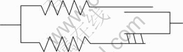
Fig.1 Microstructure inside rock model
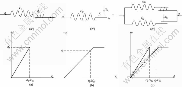
Fig.2 Mechanics response of microstructure: (a) Mechanics response of the 1st branch; (a′) The 1st branch; (b) Mechanics response of the 2nd branch; (b′) The 2nd branch; (c) Microstructure; (c′) Total mechanics response
of a gliding slice, fi is the friction coefficient of gliding slice.
The relation between stress and strain can be denoted as
 (1)
(1)
A Bingham body is shown in Fig.3 and its relation between stress and strain can be denoted as
 (2)
(2)
where k is the spring’s stiffness,  is the strength of a gliding slice, f is the friction coefficient, η is the viscosity coefficient of Newton body.
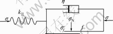
Fig.3 Structure of Bingham model
3 Constitutive relations between two kinds of rock
3.1 Constitutive relationship of combination between parallel microstructures and Bingham body in series
The structure of combination between parallel microstructures and Bingham body in series is adaptive to homogeneous rock. For there are a few cracks or holes distributing evenly in homogeneous rock, homogeneous rock can be seen as the structure of parallel microstructures and a Bingham body in series.
The loading patterns of rock are shown in Fig.4.
When σ3=0, it shows the uniaxial loading state, σ3≠0, it shows the dual-axis or triaxial loading states.
While rock undergoes uniaxial stress, the relation between stress and strain can be denoted as
 (3)
(3)
where σ and ε are the stress and strain of homogeneous rock,  and
and  are the stress and strain loading the upper part of Fig.4(a),
  and
and  are the stress and strain loading the lower part of Fig.4(a).
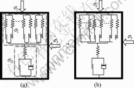
Fig.4 Loading patterns of homogeneous rock: (a) Structure of homogeneous rock; (b) Equivalent expression of Fig.4(a)


For different microstructures’ parameters, the strain is different from each other, and the time of occurrence for microstructure failures is different as well. There are many microstructures for each of the three modes under the same stress. So, we can get the result as follows:
 (4)
(4)
Under the assumption that the microstructures’ stress intensity and elastic modulus satisfy Weibull’s distribution with two parameters of (m, α), the distribution density function is
 (5)
(5)
Thereby,
(6)

If α1=α2=α, m1=m2=m then
 (7)
(7)
When rock is in the process of subjecting dual-axis or triaxial pressure, the relationship between stress and strain can be denoted as
 (8)
(8)
where


ε′ is the strain when a rock sample is subject to uniaxial stress.
Therefore,
(9)

If α1=α2=α3=α′ and m1=m2=m3=m′, then
 (10)
(10)
When σ3≠0, the normal stress of a glide slice will increase its skid resistance ability. And when σ3=0, the rock subjects to uniaxial stress and a glide slice brings into action by the autologous binding power.
The comparison between the calculated results from the model’s parallel type and the tested results is shown in Fig.5. The tested results are gotten by experiment with column specimens of homogeneous sandstone on RMT―150c testing system. The geometrical and mechanical parameters of rocks and the model parameters are shown in Tables 1 and 2 (the parameters in Table 1 are from experiments and those in Table 2 by least square method).
As the same as some factors in the part of the
Table 1 Geometrical and mechanical parameters of specimen
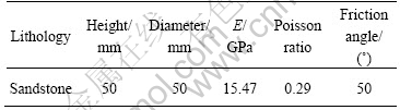
Table 2 Model parameters from stress-strain curves of rocks
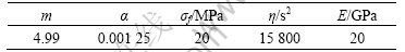
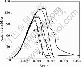
Fig.5 Comparison between calculated results by model in parallel connection and those of experiments under varied confining pressure: 1―Tested result under 2 MPa; 2―Calcu- lated result under 2 MPa; 3―Tested result under 4 MPa; 4―Calculated result under 4 MPa; 5―Tested result under 8 MPa; 6―Calculated result under 8 MPa
model’s parallel type, the initial compression stage and the confining pressure, there is a difference between the calculated strain and the tested strain, which is the strain at the end of the initial compression stage and changes with the varied confining pressure. Stresses and strains are calculated by using the model plus the strain at the end of the initial compression stage form the stress―strain curves (shown in Fig.5). When a confining pressure is taken into account, the strain in the initial compression stage should be taken into account for ε3. ε3 is gotten by adding the uniaxial compression strain at the end of the initial compression stage to the calculated ε3 or by the fitting stress―strain curve. The difference between the calculated results and the experimental data is 8.5%, 10.1% and 13.3% when the confining pressure is 2, 4 and 8 MPa, respectively, indicating that stress―strain curves by calculating agree well with those by testing. It is proven that the parallel type of the model is suitable for homogeneous rock.
3.2 Constitutive relationship of combination between microstructures and Bingham body in series
When the microstructures and a Bingham body are connected in series, as shows in Fig.6. The relationship can be denoted as
 (11)
(11)
where ε is the total strain, εi is the strain of micro- structure i, i=Ⅰ, Ⅱ, ????, N+1.
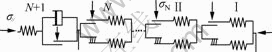
Fig.6 Combination of microstructures and a Bingham body in series connection
The results obtained according to Eqn.(1) are as follows:
 (12)
(12)
where i=Ⅰ, Ⅱ, ????, N.
From Eqn.(2) we can get another equation as follows:
 (13)
(13)
For microstructures’ parameters are different and the strain is different from each other, the time of occurrence for the microstructure failure is different as well. There are many microstructures for each of three modes under the same stress. Consequently, the results below are obtained.


 (14)
(14)
where σⅠ, σⅡ, …, σN, εⅠ, εⅡ, …, εN satisfy Eqn.(1), εN+1 satisfies Eqn.(2) and
 =
= (15)
(15)
If 
 then
then
 (16)
(16)
From Eqn.(16) it is obvious that confining pressure will restrain the axial strain. When σN=0 and εN+1=0 (without stress relaxation), Eqn.(16) becomes
 (17)
(17)
Eqn.(17) is the constitutive relation of the statistical damage model.
Generally, the rock with cracks induces brittle failure at the beginning, and its inner friction is all through serving its function. The brittle failure mainly is the localized failure to come into being the failure surface and then is followed by sliding along with the failure surface. Assuming the crack’s tilt angle is equal to the failure surface’s one and it equals θ, then the rock’s loading pattern is shown in Fig.7 and some equations are as follows:
 (18)
(18)
where σ//, σN and ε are as the same as those in Eqn.(11), l is the length of the failure surface, H is the height of the sample, L is the side length of square samples or the diameter of circle samples.
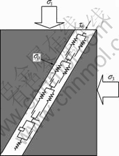
Fig.7 Loading pattern of rock with cracks
When σ3=0, it shows the sample subjecting to uniaxial stress; σ3≠0, it shows the dual-axis or triaxial stress.
According to Mohr circle theory, there are
 (19)
(19)
According to Eqns.(13)-(19), we can get an equation as follows:
 (20)
(20)
There are some factors affecting the axial strain and they are the confining pressure, the height of the sample, and the length, tilt and friction coefficient of the failure’ surface.
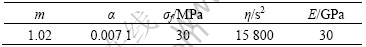
The testing data of cuboid specimens of sandstone in Ref.[9] were used to prove the proposed model’s state, as shown in Fig.8. The geometrical and mechanical parameters of rocks and the model parameters are listed in Table 3 and Table 4, respectively (the parameters in Table 3 are from Ref.[9] and the parameters in Table 4 by least square method).
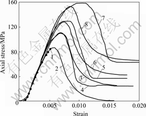
Fig.8 Comparison between calculating results by model’s series type and experiment results: 1―Tested results without confining pressure; 2―Calculated results without confining pressure; 3―Tested results under 3 MPa; 4―Calculated results under 3 MPa; 5―Tested results under 5 MPa; 6―Calculated results under 5 MPa; 7―Tested results under 8 MPa; 8―Calculated results under 8 MPa
Table 3 Geometrical and mechanical parameters of rocks
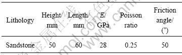
Table 4 Model parameters from stress-strain curves of rocks
As the same as factors in the part of the model’s parallel type, the initial compression stage and the confining pressure or ε3 are taken into account in the party of its series type. It is gotten from Fig.8 that a sandstone specimen fails suddenly after the stress is up to the peak value due to testing machine, while there is a descent stage after the stress’ peak value in the model’s calculated result. And it is also shown that there is a little difference between the calculation results and the experimental data when the confining pressure is low and there is larger difference when the confining pressure is high (e.g. up to 8 MPa). The difference between the calculation results and the experimental data is 4.3%, 7.3% and 11.1% when the confining pressure is 0, 2 and 4 MPa, respectively, and the difference is 16.2% when the confining pressure is 8 MPa.
4 Conclusions
1) Rock is made up of many microstructures and a Bingham body. The microstructure is made up of two embranchments that are the unit of a spring and a gliding slice in series connection and the unit of a spring and a cementation bar in series connection. And these microstructures are arranged disorderly or in the order of certain state. The unified constitutive model of rock built by using mechanics elements is reasonable. And different types of rock may be described with mechanics elements, whose distributions are different.
2) For there are a few cracks or holes distributed evenly in homogeneous rock, homogeneous rock is considered the structure of parallel microstructures and a Bingham body in series connection. The correctness is proven by experiments.
3) Rock mass with cracks or the rock mass with cracks formed through loading and unloading is considered the combination of these microstructures in series connection, as is proven by other testing data.
4) The confining pressure’s influence is taken into consideration in the two kinds of rock. The difference between the calculation results and the experimental data mainly is induced by the rock’s consolidation at the initial compression stage.
References
[1] CHEN Feng, SUN Zong-qi, XU Ji-cheng, ZHANG Jing-yi. A composite material model for investigation of microfracture mechanism of brittle rock subjected to uniaxial compression [J]. J Cent South Univ Technol, 2001, 8(4): 258-262.
[2] LIU Li, QIU De-xian, YAN Zong-ling. Study on damage constitutive model of three-dimension stratified composite rock [J]. Chinese Journal of Rock Mechanics and Engineering, 2002, 21(5): 621-625. (in Chinese)
[3] ZUO Yu-jun, LI Xi-bing, ZHAO Guo-yan. A catastrophe model for underground chamber rock burst under lamination spallation bucking [J]. J Cent South Univ: Science and Technology, 2005, 36(2): 311-316. (in Chinese)
[4] NARDIN A, SCHREFLER B. Numerical simulation of rock behaviour through a discrete model[J]. Solids and Structures, 2004, 41(21): 5945-5965.
[5] LI Shi-ping, WU Zhen-ye, HE Yong-nian, LI Xiao. Concise tutorial rock mechanics [M]. Beijing: Coal of Technology Press, 1996: 39-58. (in Chinese)
[6] DENG Rong-gui, ZHOU De-pei, ZHANG Zhuo-yuan. A new rheological model for rocks [J]. Chinese Journal of Rock Mechanics and Engineering, 2001, 20(6): 780-784. (in Chinese)
[7] ZHANG Gui-ke, XU Wei-ya. Analysis of a new visco-elasto-plastic model for jointed rock mass [J]. Chinese Journal of Rock Mechanics and Engineering, 2006, 25(S1): 2894-2901. (in Chinese)
[8] SHEN Zhu-jiang, CHEN Tie-lin. Simulation of rock deformation and failure by binary medium model [J]. Hydro Science and Engineering, 2004, 3(1): 1-5. (in Chinese)
[9] ZHANG Ping, LI Ning, HE Lan-ruo. Research on localized progressive damage model for fractured rocklike materials [J]. Chinese Journal of Rock Mechanics and Engineering, 2006, 25(10): 2043-2050. (in Chinese)
[10] GRADY D E, KIPP M E. Continuum modeling of explosive fracture in oil shale [J]. Int J Rock Mech Min Sci and Geomech Abstr, 1980, 17(2): 147-157.
[11] LI Xi-bing, GU De-sheng. Rock impact dynamics [M]. Changsha: Central South University of Technology Press, 1994: 51-68. (in Chinese)
[12] CHANG K J, YANG T W. A constitutive model for the mechanical properties of rock[J]. Int J Rock Mech Min Sci and Geomech Abstr, 1982, 19(3): 123-133.
[13] ZUO Yu-jun, LI Xi-bing, WANG Wei-hua, ZHANG Yi-ping, MA Chun-de, YAN Chang-bin. Catastrophe model and its experimental verification of static loading rock system under impact load [J]. J Cent South Univ Technol, 2006, 13(3): 281-285.
[14] LI Xi-bing, ZUO Yu-jun, MA Chun-de. Constitutive model of rock under coupled static-dynamic loading with intermediate strain rate [J]. Chinese Journal of Rock Mechanics and Engineering, 2006, 25(5): 865-874. (in Chinese)
[15] LI Xi-bing, ZUO Yu-jun, WANG Wei-hua, MA Chun-de, ZHOU Zi-long. Constitutive model of rock under static-dynamic coupling loading and experimental investigation [J]. Trans Nonferrous Met Soc China, 2006, 16(3): 714-722.
[16] DELHOMME F, MOMMESSIN M, MOUGIN J P, PERROTIN P. Simulation of a block impacting a reinforced concrete slab with a finite model and a mass-spring system[J]. Engineering Structure, 2007, 29(11): 2844-2852.
(Edited by YANG Hua)
Foundation item: Projects(10472134, 50490274) supported by the National Natural Science Foundation of China
Received date: 2007-10-21; Accepted date: 2007-12-27
Corresponding author: YE Zhou-yuan, Doctor candidate; Tel: +86-731-8879612; E-mail: yezhouyuan@126.com

