An anisotropic constitutive model of geomaterials based on true triaxial testing and its application
��Դ�ڿ������ϴ�ѧѧ��(Ӣ�İ�)2017���6��
�������ߣ�Frederick Nai Charkley ������
����ҳ�룺1430 - 1442
Key words��true triaxial test; stress induced anisotropy; constitutive model; complex stress state; finite element method (FEM)
Abstract: Series of testing on coarse grained soils were carried out with a true triaxial testing apparatus. The loads were applied from the major principal and minor principal directions, respectively, to simulate the construction and water impounding process of a rock fill dam. The stress and strain relationships induced by the different loading methods were investigated. A remarkable stress-induced anisotropy under complex stress state was observed. Contrary to popular assumptions in traditional numerical analysis and constitutive models, it was found that different elastic modulus and Poisson ratio exist in different principal directions in rock fill dams. From the testing results, an anisotropic constitutive model based on Duncan-Chang nonlinear model is presented to overcome the limitations of axi-symmetric assumptions in conventional triaxial experiments and constitutive models. Both models were then applied in FEM analysis of an under-construction earth core high rock soil filled dam with the focus on hydraulic fracturing. The study reveals the major biases that exist when numerical analysis and constitutive models do not give serious consideration to the intermediate principal stress and anisotropy effects in soil rock built structures.
Cite this article as: ZHANG Kun-yong, Frederick Nai Charkley. An anisotropic constitutive model of geomaterials based on true triaxial testing and its application [J]. Journal of Central South University, 2017, 24(6): 1430-1442. DOI: 10.1007/s11771-017-3547-0.
J. Cent. South Univ. (2017) 24: 1430-1442
DOI: 10.1007/s11771-017-3547-0

ZHANG Kun-yong(������)1, 2, Frederick Nai Charkley1, 2
1. Key Laboratory of Ministry of Education for Geomechanics and Embankment Engineering, Nanjing 210098, China;
2. Geotechnical Research Institute, Hohai University, Nanjing 210098, China
 Central South University Press and Springer-Verlag Berlin Heidelberg 2017
Abstract: Series of testing on coarse grained soils were carried out with a true triaxial testing apparatus. The loads were applied from the major principal and minor principal directions, respectively, to simulate the construction and water impounding process of a rock fill dam. The stress and strain relationships induced by the different loading methods were investigated. A remarkable stress-induced anisotropy under complex stress state was observed. Contrary to popular assumptions in traditional numerical analysis and constitutive models, it was found that different elastic modulus and Poisson ratio exist in different principal directions in rock fill dams. From the testing results, an anisotropic constitutive model based on Duncan-Chang nonlinear model is presented to overcome the limitations of axi-symmetric assumptions in conventional triaxial experiments and constitutive models. Both models were then applied in FEM analysis of an under-construction earth core high rock soil filled dam with the focus on hydraulic fracturing. The study reveals the major biases that exist when numerical analysis and constitutive models do not give serious consideration to the intermediate principal stress and anisotropy effects in soil rock built structures.
Key words: true triaxial test; stress induced anisotropy; constitutive model; complex stress state; finite element method (FEM)
1 Introduction
In most geotechnical applications, the use of axi-symmetric triaxial testing with isotropic assumptions is widely accepted [1, 2]. In this test, load is applied from the major principal stress direction and the stresses in the other directions are assumed to be symmetric. Most popularly known soil constitutive models are also developed based on this symmetric triaxial testing. However, in practice the loads may be applied in different directions under a three-dimensional complex stress state. Thus, anisotropy is induced both by the initial complex stress states and the different loading methods. In this regard, the traditional triaxial test and constitutive models such as Duncan-Chang hyperbolic E-v model, although very popular, cannot fully describe such anisotropy and may find it difficult in interpreting the yielding and failure for rocks and soils. Soils, rocks and many artificial composites are examples of geomaterials that display anisotropy in their physical characteristics, mechanical properties, structure and constitutive relationship. Two main kinds of anisotropy can be identified in such materials. Anisotropy resulting from the physical characteristics and entirely independent of the applied stresses and strains is referred to as inherent anisotropy [3, 4]. This is attributed to the initial grain orientation of the soil mass before any load is applied. The second is stress induced anisotropy which is a physical characteristic exclusively due to the strain associated with an applied stress, especially under complete stress state [5-7].
Literature available in the past several decades contains significant information regarding the importance of anisotropy in geomaterials [4, 5, 8-16]. The comprehensive study [4, 5] and the microscopic observation of sand fabric [8] in the early 1970��s serve as the basic reference for soil anisotropy. It is now generally acknowledged that the effects of anisotropy in geomaterials are remarkable and traditional constitutive soil models with isotropic assumptions cannot be relied on to fully describe observed real phenomenon [17-19]. This has been well demonstrated through intermediate shear strength and strain behavior in tunneling by LEE and ROWE [20] and SIMPSON et al [21]; discrepancies in strength with changes in the orientation between the direction of deposition and that of the major principal stress in San Francisco Bay mud by KIRKGARD and LADE [11] and also in boundary value problems by SIDDIQUEE et al [22]. Hence, the proper evaluation of anisotropy in soil/rock built structures has become inevitable.
It has been suggested that when traditional models are applied to the stress and deformation computation of a rock-fill dam, there may be lots of inconsistencies with practical conditions [23-26]. However, not much data is available in literature to study the stress induced anisotropy which significantly influences the stress and strain relationships in rock fill dams. In this work, the construction and impounding procedure of a rock-soil filled dam is used as a typical example to demonstrate how the use of axi-symmetric assumptions is insufficient to simulate practical field conditions. During the construction of the dam body, gravity load acts in the major principal direction but in the impounding process the water load acts in the minor principal direction. Even though the use of rock fill material for dam construction is very economical, the coarseness of the particles, their interlocking property, boundary conditions and general behavior when water is impounded makes it very difficult to replicate in the laboratory using axi- symmetric assumptions.
Furthermore, considering the fact that the Duncan Chang E-v model is very popular in China but has a lot of limitations for the modeling of anisotropic deformations under complex stress states, the current study attempted to revise it by treating the stress-strain relationship for each principal direction differently under a three-dimensional stress condition rather than having just one stress-strain relationship for all principal stress directions as assumed in ordinary triaxial tests. Thus, a revised model was obtained from the Traditional Duncan E-v model by adjusting the model parameters to reflect actual field conditions based on the laboratory testing results. Then, the traditional Duncan-Chang E-v constitutive model and the revised anisotropic model were applied in an FEM analysis. The results were discussed with focus on hydraulic fracturing in the dam core wall because it plays a significant role in the development of cracks in the core of dams [27]. To this end, a comprehensive laboratory investigation was carried out using TSW-40 true triaxial apparatus. The aim of using this new device was to obtain a realistic representation of the complex stress state conditions and the influence of anisotropic stress and deformation on the earth core dam��s stress and deformation.
This article��s originality directly lies on: (1) the use of a new true triaxial device for triaxial testing which offers better flexibility for load application, (2) the attainment of a better constitutive model that can replace and eliminate the limitations in traditional models, and (3) the verification of the experimental results through the use of data from a real field project on a rock fill dam with laboratory test results using FEM analysis.
In this work, a special testing device referred to as TSW-40 for true triaxial testing which offers better flexibility for load systems (where ��1�٦�2�٦�3) and developed at the Institute of Geotechnical Engineering, Hohai University, China, was used. A general view of the device is shown in Fig. 1(a). By employing this new device, loads could be independently applied from the three principal directions and controlled by a computer. The TSW-40 true triaxial apparatus was designed with a combination of rigid and flexible boundaries. This makes it very convenient for testing coarse materials, such as sand, gravel and other coarse grained soil composites. Cuboidal samples of sizes ranging from 12.0 cm��12.0 cm��12.0 cm to 12.0 cm��12.0 cm��6.0 cm could be prepared to meet different test requirements.
The device has two rigid boundaries; one is in the vertical direction with a top cap and a pedestal and another in the horizontal direction. In the horizontal direction, there is also a soft boundary with a pair of two confining water bags. From the use of an advanced strain measurement technique and loading control system, the device can take measurement of changes in volume and strain. Using the TSW 40 true triaxial apparatus, it is possible to overcome the limitation in the traditional triaxial device which is that the intermediate principal stress and major principal stress must be based on the minor principal stress. Here, an independent loading system is used to apply load in the minor principal stress direction in place of the usually used gas or water pressure chamber (confining pressure loading methods). Thus, it is possible to achieve any desired loading range in the three principal stress axes and can be used to develop realistic stress strain relationships and constitutive models.
The apparatus generally consists of three main components which are a loading system, a controlling and measurement system, and an output system. This is depicted in Fig. 1(b). A special closed rectangular rubber membrane with opened upper and lower ends is used for sampling. An aluminum alloy frame with a rubber gasket seal provided at the bottom and a top plate also placed at the upper part of the sampler helps to secure the specimen. Drainage tubes are connected to the specimen cap and the floor of the pressure plate to control drainage for drained and undrained testing. Measurement of parameters is mainly done by a computer automatically by collecting displacement and volumetric data from displacement and pressure sensors. The output system displays test results in the form of data, graphs and charts.
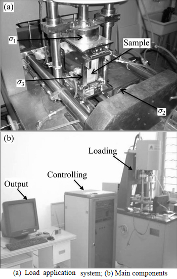
Fig. 1 TSW 40 true triaxial apparatus:
2 Material and methods
The material used in this work consisted of a compound mixture of clay and gravel at a mass ratio of 1:1. The soil was obtained from the core wall of Shuangjiangkou rock soil filled dam. The particle sizes of the coarse grains range from 2 mm to 5 mm. The soil was characterized by a natural moisture content of 15.1%, liquid limit of 33.4% and a plastic limit of 19.6%. It had plasticity index of 13.8 and a dry density of 1.93 g/cm3.
The experimental procedure consisted of two series of triaxial testing depending on the direction in which the load was applied. In the first series, the load increment was applied from the major principal direction and in the second series the load increment was applied from the minor principal direction. To begin the test, an initial confining pressure, ��30, was applied equally in all principal directions to achieve a three dimensional stress state. The major principal stress, ��1 and intermediate principal stress, ��2 were then increased proportionally in accordance with the stress ratio, b (b=(��2-��3)/(��1-��3)). Then, to simulate the construction and water impounding process in the dam, additional loads were applied from the major principal direction and the minor principal direction, respectively. The detail testing procedure is described in the following section.
First, an initial confining pressure ��30 was imposed from all three principal directions. The values of ��30 chosen were 100 kPa, 200 kPa and 400 kPa. Loading was applied from zero and increased to ��30. This generated an initial isotropic stress state to stabilize the sample. Based on the study of the effect of initial fabric on deformation characteristics conducted by KULHAWY and DUNCAN [28], inherent anisotropy was eliminated after isotropic pressure was applied and increased. In other words, the isotropic confining stress eliminated the sample��s inherent anisotropy produced by the sampling process, leaving only stress induced anisotropy. Now it was necessary to replicate the original three-dimensional stress states of the soil elements in the dam core wall. This was done by increasing the major principal stress ��1 and the intermediate principal stress ��2 to certain values in accordance with the different required b0 values (b0 was defined as the initial middle principal parameter, b0=(��2-��3)/(��1-��3)). Finally, the construction process of the dam was simulated by applying stress increment ����1 from the major principal direction for series 1. For the minor principal direction and major principal direction loading series tests, the initial testing steps were the same. The difference only existed in the final step where in the minor principal loading test, the stress increment ����3 was rather applied from the minor principal direction to simulate the water impounding process. The stress paths that the specimens experienced in both testing series are depicted in Fig. 2.
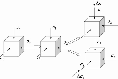
Fig. 2 Stress path of true triaxial testing
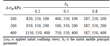
In consistence with different ��30 values, the test was divided into three sub-groups i.e. 100 kPa, 200 kPa and 400 kPa, so as to compare the impact of different initial confining pressures on the test results. For each ��30, the b0 was also varied. It was set to 0.2, 0.5 and 0.8. The different stress states under which samples were tested in this work are summarized in Table 1 for each of the three sub-groups.
Every specimen was kept under the same initial density and moisture content before the initial confining stress, ��30, was applied. In each testing step, the three- strain increments, the volume changes and other related parameters were measured. However, only the increments of stress and strain in the third step were used in the analysis to focus the study on the effect of additional stress and strain increment caused by increasing major principal stress load ����1 or minor principal stress load ����3.
Table 1 Initial stress states of true triaxial tests (kPa)
3 Test results and discussion
For series 1 tests, the load increment was applied along the major principal direction. The stress and strain increment relationships under 100 kPa, 200 kPa and 400 kPa initial confining pressure according to different b0 are shown in Figs. 3, 4, and 5 respectively. The major principal stress increment ����1 increased until failure in all the specimens.
Figures 3(a), 4(a) and 5(a) show the relationship between the major principal stress increment ����1 and the major principal strain increment ����1 under different ��30 and different b0. It can be noted that the strength of the specimens increased with the increment of ��30 for a fixed value of b0, which means that the larger the initial confining stress ��30, the higher the elastic modulus. This kind of stress-hardening property, which is due to the arrangement of grains and friction among soil particles, has been verified in many traditional triaxial tests. Also, it can be noted that for each ��30, the strength of the specimen increased with increasing b0 from 0.2 to 0.5 and 0.8. This can be attributed to the fact that increasing the intermediate principal stress ��2, constrains the lateral deformation of the specimen and thus influences the axial deformation tendency. In other words, the bigger the intermediate principal stress ��2, the stiffer the specimens. It could be deduced that when loads are applied from the major principal direction, the elastic modulus of the soil increases in accordance with the increment of the initial confinement pressure ��30 and intermediate principal stress ��2 under complex stress states.
Figures 3(b), 4(b) and 5(b) give the relationship between the major principal strain and intermediate principal strain increment under different ��30, and b0. This reflects the Poisson ratio characteristics of ��21. Figures 3(c), 4(c) and 5(c) give the relationship between the major principal strain and minor principal strain increment under different ��30 and b0, which represent the Poisson ratio characteristics of ��31. From these curves, it could be noted that both ��21 and ��31 decreased with increasing confining pressure under the same initial b0. Also, both ��21 and ��31 decreased with increasing initial b0 under the same confining pressure. Besides, under the same stress condition (confining pressure and initial b0), ��31 is generally greater than ��21.
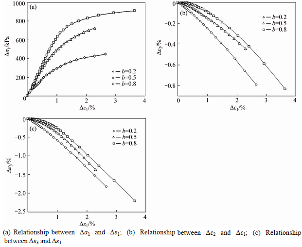
Fig. 3 Test results of s3=100 kPa for loading from s1 direction:
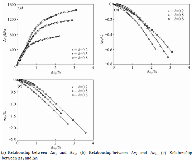
Fig. 4 Test results of s3=200 kPa, loading from s1 direction:
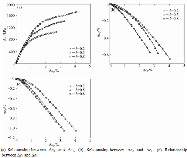
Fig. 5 Test results of s3=400 kPa, loading from s1 direction:
For series 2 tests, the load increment was applied along the minor principal direction. The stress and strain increment relationships under 100 kPa, 200 kPa and 400 kPa confining pressures according to different b0 values are shown in Figs. 6, 7 and 8, respectively. In this test, the minor principal stress increment, ����3, was limited to a certain magnitude to avoid rotation of the principal stress axes, which could produce additional deformation and can have a very considerable influence on soil behaviors.
Figure 6(a), 7(a) and 8(a) show the relationships between the minor principal stress ����3 and minor principal strain ����3 under different initial confining pressures, ��30, and different b0. It can be observed that strength increases with the increment of the initial confining stress, ��30, for a given value of b0. This implies that the larger the confining stresses, the higher the elastic modulus. This stress-hardening property is similar to the results obtained in series 1 testing. However, for each confining pressure, ��30, the strength of the specimen decreased with the increment of the initial b0, from 0.2 to 0.5 and 0.8. Thus, the material exhibited stress-softening behaviors when the loads were applied from the minor principal direction. Therefore, it can be deduced that increasing the intermediate principal stress ��2 releases the lateral deformation in the minor principal direction. Hence, the bigger the intermediate principal stress, ��2, the softer the specimens will be under such loading conditions.
Figures 6(b), 7(b) and 8(b) give the relationship between the minor principal strain and major principal strain increment under different confining stresses, ��30, and b0. This represents the Poisson ratio characteristics of ��13. Figures 6(c), 7(c) and 8(c) also show the relationship between the minor principal strain and the middle principal strain increment under different initial confined stress ��30 and b0, which represent the Poisson ratio characteristics of ��23. From these curves, it could be noted that ��23 and ��23 are generally negative. This means that under such stress conditions, when stress increment was applied in the minor principal stress direction, the corresponding lateral deformation in both the major and intermediate principal directions was compression but not expansion. This finding is the most remarkable distinction between series 1 and series 2 test results. To throw more light on this, the initial tangent modulus and Poisson��s ratio obtained from the above different testing methods have been summarized in Tables 2 and 3.
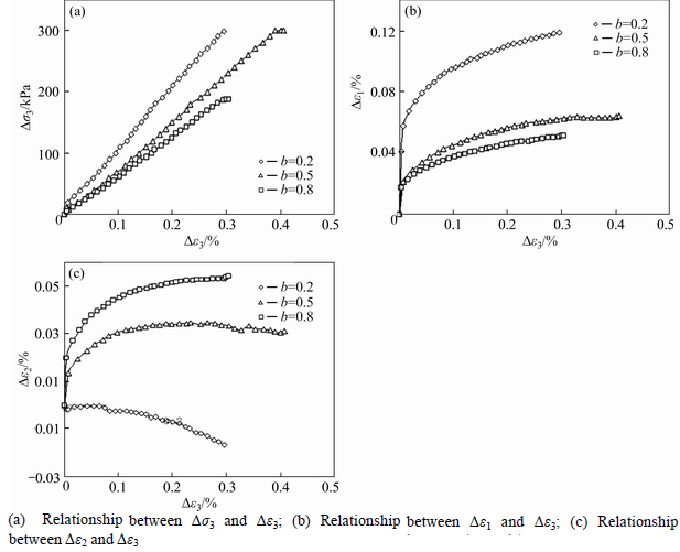
Fig. 6 Test results of s3=100 kPa, loading from s3 direction:
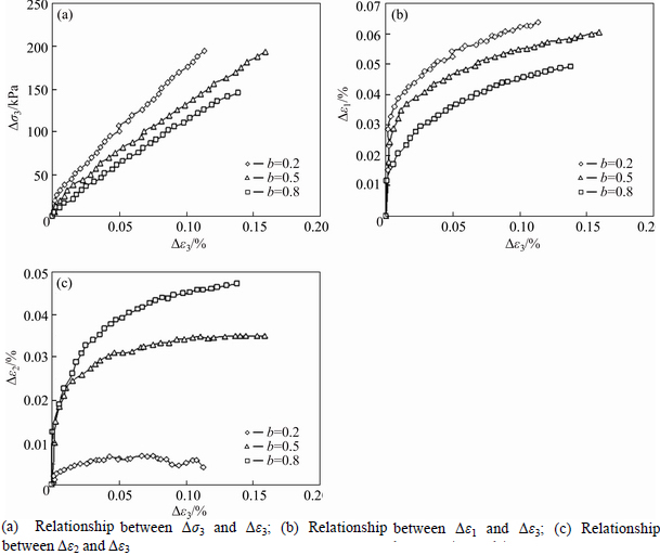
Fig. 7 Test results of s3=200 kPa, loading from s3 direction:
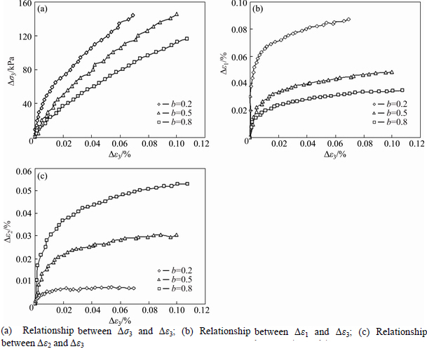
Fig. 8 Test results of s3=400 kPa, Loading from s3 direction:
Table 2 Initial tangent modulus and Poisson ratio for series 1
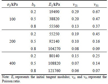
Table 3 Initial tangent modulus and Poisson ratio for series 2
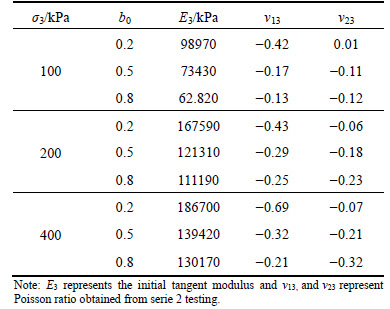
From the analysis results presented in Tables 2 and 3, it is exhibited that the values of initial tangent modulus in different principal directions are determined both by the initial confining pressure, ��30, and the intermediate principal stress parameter b0. In addition, the direction in which the load is applied can also have great influence on the value of the initial tangent modulus. Generally, the E3 is greater than E1 under the same initial stress condition. It is also clear that Poisson ratio changes under different stress conditions and in different principal directions contrary to assumptions in most soil constitutive models where the soil is taken as an isotropic material and the same modulus and Poisson ratio are applied to describe the stress and strain relationship in all three principal directions. So in this study, the true triaxial tests have displayed that there are quite different stresses and strains in the different principal directions. Traditional models with isotropic assumption, such as Duncan-Chang hyperbolic E-v model which is popularly used in China therefore falls short when used in stress and deformation analysis of rock fill dams.
3.1 Development of new model from conventional Duncan-Chang constitutive model
The Duncan-Chang E-v model is popularly applied in geotechnical engineering in China, especially in dam stress and deformation calculations. The model is nonlinear and elastic with two isotropic elastic constants, i.e., elastic modulus and Poisson ratio (or the bulk modulus, B). It is theoretically founded on the well known generalized Hooke��s law equation and developed based on stress-strain curves from drained triaxial compression tests which are approximated by a hyperbola. Thus, the soil is modeled as a nonlinear elastic material with a hyperbolic stress-strain function. The stress-dependent elastic tangential modulus (Et) for a given stress condition, is given by
 (1)
(1)
where ��1 is the major principal stress; ��3 is the minor principal stress; pa is atmospheric pressure; �� is the friction angle; c is the cohesion; K is modulus number, a dimensionless parameter which represents elastic modulus; n is the modulus exponent that governs the stress dependence of K on ��3; Rf is the failure ratio.
The unloading and reloading behavior using the Duncan-Chang model is given by
 (2)
(2)
where Kur is the unloading-reloading modulus number (Kur=1.2-1.5 K).
The tangent Poisson ratio is expressed as
 (3)
(3)
where
 (4)
(4)
D, F and G are stress dependent material parameters determined by triaxial testing; G is the value of vt at ����3= pa; F is the decrease of vt for a ten-fold increase in ��3 and D is a parameter expressing the rate of change of vt with strain.
From the true triaxial test results presented in this work, the Poisson ratio, changed under different complex stress conditions. In some cases, the Poisson ratio was even negative. It was concluded that the lateral deformation was not dilative but compressive. The true triaxial tests also proved that the lateral deformation produced by stress increment in the minor principal stress direction is rather smaller than that in the major principal stress direction. For the major principal stress, it is the highest stress tensor of the three principal stresses. This implies that when applying stress increment in this direction, the lateral restraints are smaller, or in other words, the lateral deformations are larger. So, Poisson ratio, v, is rather big. On the contrary, for the minor principal stress, it is the smallest stress tensor because when the stress increment is applied in this direction, there are rather high lateral restraints in the other two directions. That makes it difficult to produce large deformations. Thus Poisson ratio is relatively small. During the impounding process when water load is applied to the dam body, the pressure acts in the minor principal stress direction. Based on the fact that the water pressure that is applied on a dam body acts in the minor principal direction, the Poisson ratio should be much smaller than that obtained from traditional triaxial tests, in which the load is applied from the major principal direction. As a result of this difference, bigger Poisson ratios are applied in calculations. Therefore, the deformations calculated with these Poisson ratios are rather larger than in practice.
Considering this shortcoming of the Duncan-Chang model for the modeling of anisotropic deformation under complex stress states, the Duncan-Chang E-v model is revised by adjusting the model parameters to reflect the stress anisotropy. Based on the true triaxial compression test results, the relationship between the stress increments and strain increments are described and displayed as
 (5)
(5)
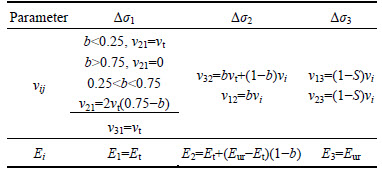
From Eq. (5), there are six Poisson ratios and three elastic modulus. The different Poisson ratios and elastic modulus were applied in the different directions as shown in Table 4 where b is the intermediate principal stress parameter; S is the stress level, S=(s1-s3)/(s1-s3)f; (s1-s3)f represents the deviator stress at failure; vt, vi, Et, Eur could be determined through the Duncan-Chang E-v model. All parameters can be obtained through the conventional triaxial test, but the elastic module and Poisson ratio in different directions are adjusted to simulate the anisotropic effects. This enables a clearer description of the stress induced anisotropy under complex stress conditions which is reflected in the true triaxial test results.
Table 4 Elastic modulus and Poisson ratio in different directions
3.2 Application of revised model
The many high and ultra-high rock-soil fill dams constructed in China and all over the world make it necessary to carry out safety assessments during the design, construction and operation process. The stress and deformation of the core walls are related to the resistance to hydraulic fracturing. It is important to produce reasonable simulation and evaluation of the stress and strain conditions on the core wall and how the results relate to the safety of the whole dam.
Shangjiangkou hydropower station is one of the key projects under the development of the Dadu River Hydropower Cascade controlled reservoirs of the Dadu River Basin hydropower cascade development project. The Dam site is mountainous with deep meandering valleys. The Shuangjiangkou earth core rock fill dam is located in the southwest mountain gorge and the river bed covers a maximum thickness of about 68 m. The maximum height of the dam is 312 m (including 6 m thick base). The upstream slope is 1:2.0 and the downstream slope is 1:1.90. The elevation of the center top of the wall is 2508.00 m, which is higher than the maximum static water level (2504.51 m). The slope of the core wall is 1:0.2 and the largest section of the core wall bottom elevation is 2202.00 m down the river with a width of 128.00 m. There are two filtering layers for protection of the soil materials outside the core wall. The filter slope is 1:0.2. Figure 9 shows a typical cross section of the dam.
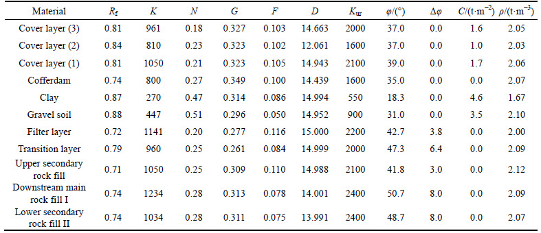
The dam shell was considered as a completely permeable material and the core was treated as a fully waterproof material. A total of twenty five calculation load steps were applied to simulate the practical construction and water impounding process. The nonlinear material parameters used in the calculation are shown in Table 5.
The bedrock and concrete materials were assumed to be elastic and the parameters are listed below:
Bedrock ��=2.4 t/m3, j=48��, c=2000 kPa, elastic modulus = 35 GPa, Poisson ratio = 0.17;
Concrete ��=2.44 t/m3, j=48��, c=2000 kPa, elastic modulus = 30 GPa, Poisson ratio = 0.17.
The stress and displacements calculated with the Duncan-Chang model are presented in Fig. 10. The stress and displacements calculated with the revised model are shown in Fig. 11.
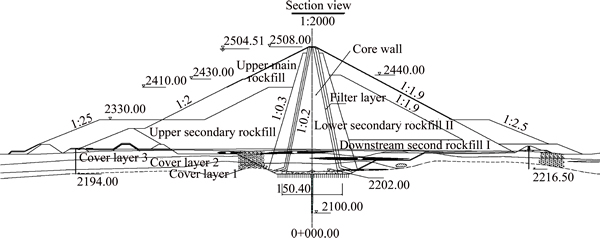
Fig. 9 Typical cross section of dam (Unit: m)
Table 5 Parameters of dam materials
The maximum displacements of the dam body using the Duncan-Chang model and the new anisotropic model are compared.
From Figs. 10, 11, it can be observed that the stress and deformation distribution obtained by both models generally appear to be the same, but the magnitudes are different. The horizontal displacements calculated by the revised model are greater than those from the Duncan-Chang model results. The major principal stresses are nearly the same. The minor principal stresses obtained by the Duncan-Chang model are smaller than the revised model results. Usually, the possibility of failure is determined by the ratio of water pressure to stress ratio in the water load direction or the minor principal stress (when the ratio is greater than 1.0 failure will occur). This criterion was applied in the hydraulic fracturing analysis. Figure 12 shows the water pressure and the ratios of stress component distributed along the core wall height:
From Fig. 12, the stress along the core wall calculated by the anisotropic model is greater than that obtained by the Duncan-Chang model. Furthermore, the minor principal stress is observed to be smaller than the water pressure at some locations in the Duncan-Chang model. This indicates that there may be hydraulic core fracturing at these locations. But all the results obtained from the revised anisotropic model points out that the water pressure is smaller than all the stress components and thus the core wall is safe. This reveals the considerable bias that exists in conventional models and shows that when anisotropy is disregarded in the numerical analysis, the results may be misleading.
4 Conclusions
A new true triaxial apparatus was employed to carry out a series of testing on gravel materials under a three dimensional stress state. Typical three-dimensional stress states were simulated by setting different initial confining stresses, ��30, and b0, and then a load increment was applied from either the major principal stress, ��1, direction or minor principal stress, ��3, direction. Experimental results show that under three dimensional stress conditions, significant stress-induced anisotropy is produced. A revised model was then proposed by applying different elastic modulus and Poisson ratios to describe the stress-strain relationship in all three principal directions based on Duncan-Chang E-v model.
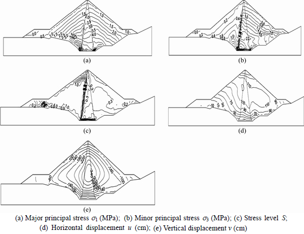
Fig. 10 Calculated results with Duncan-Chang model for:
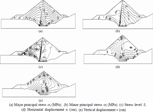
Fig. 11 Calculated results with Anisotropic model:
Table 7 Maximum displacements comparison

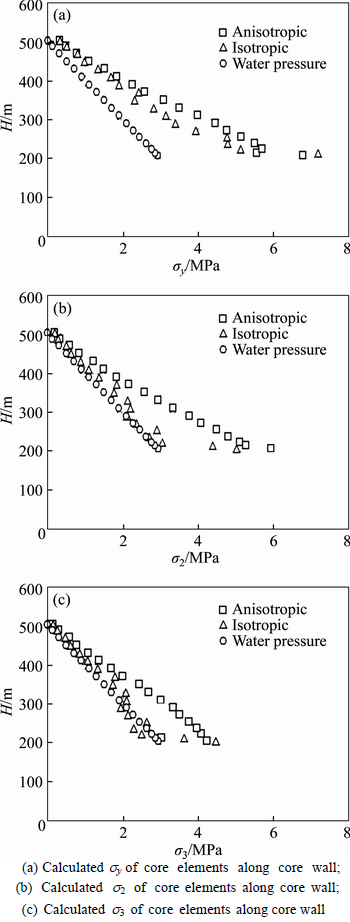
Fig. 12 Stress distribution along core wall:
The traditional Duncan-Chang E-v constitutive model and revised anisotropic model were applied in an FEM analysis on an under construction high earth core wall dam. The stress induced anisotropy effects on the hydraulic fracturing of the earth core wall was discussed. It was found that the dam was safer against hydraulic fracturing by the revised anisotropic model compared with the Duncan-Chang E-v model.
This work reveals the considerable bias that exists with numerical analysis results based on traditional isotropic constitutive models which cannot describe practical stress and strain relationships of geomaterials under three-dimensional stress states.
It is suggested based on the true triaxial testing results that when carrying out numerical analysis on practical cases, this kind of stress-induced anisotropy should be taken into consideration. Enough consideration should be given to the intermediate principal stress and anisotropic effects when applying constitutive models on soils.
References
[1] ISMAIL M A, JOER H A, SIM W H, RANDOLPH M F. Effect of cement type on shear behaviour of cemented calcareous soil [J]. J Geotech Eng ASCE, 2002, 128(6): 520�C529.
[2] MA S K, HUANG M S, HU P. Soil-water characteristics and shear strength in constant water content triaxial tests on Yunnan red clay [J]. Journal of Central South University, 2013, 20(5): 1412-1419.
[3] CASAGRANDE A, CARILLO N. Shear failure of anisotropic materials [J].J Boston Soc Civ Eng,1944, 31(4): 74�C87.
[4] ARTHUR J R F, MENZIES B K. Inherent anisotropy in a sand [J]. Geotechnique, 1972, 22(1): 115-128.
[5] ARTHUR J R F, CHUA K S, DUNSTAN T. Induced anisotropy in a sand [J]. Geothchnique, 1977, 27(1): 13-30.
[6] SUSHIL K, CHAUDHARY J K. Effects of initial fabric and shearing direction on cyclic deformation characterstics of sands [J]. Soils and foundations, 2002, 42(1): 147-157.
[7] ABELEV A V, LADE P V. Effects of cross anisotropy on three-dimensional behavior of sand I: Tress�Cstrain behavior and shear banding [J]. J Eng Mech, 2003, 29(2),
[8] ODA M. Initial fabrics and their relations to mechanical properties of granular materials [J].Soils Found,1972, 12(1): 17-36.9.
[9] ARTHUR R F, CHUA K S, DUNSTAN T, RODRIGUEZ D, CAMINO J I. Principal stress rotation: A missing parameter [J]. Journal of the Geotechnical Engineering Division, ASCE, GT4, 1980: 419-433.
[10] ATKINSON J H, RICHARDSON D, STALLEBRASS S E. Effect of recent stress history on the stiffness of overconsolidated soil [J]. G��otechnique, 1990, 40(4): 531-541.
[11] KIRKGARD M M, LADE P V. Anisotropic Three-Dimensional Behavior of a normally consolidated clay [J]. Canadian Geotech. 1993, 30: 848-858.
[12] CALLISTO L, CALABRESI G. Mechanical Behaviour of a Natural Soft Clay [J]. Geotechnique, 1998, 4(4): 495-513.
[13] LI X S, DAFALIAS Y F. Constitutive modeling of inherently anisotropic sand behavior [J]. J Geotech Geoenviron Eng, 2002, 128(10): 868-880.
[14] LADE P V, ABELEV A V. Characterization of cross-anisotropic soil deposits from isotropic compression tests [J]. Soils Found, 2005, 45(5): 89-102.
[15] ABELEV A V, GUTTA S K, LADE P V, YAMAMURO J A. Modelling cross anisotropy in granular materials [J]. J Eng Mech, 2007, 133(8): 919-932.
[16] ZHANG Yu, XU Wei-ya, GU Jin-jian, WANG Wei. Triaxial creep tests of weak sandstone from fracture zone of high dam foundation [J].Journal of Central South University, 2013,20(9): 2528-2536.
[17] YIN Zong-ze. The effect of soil lateral dilation behavior on stress and strain of earth and rock-fill dams [J]. Chinese Journal of hydraulic Engineering, 2000, 44(7): 1-9. (in Chinese)
[18] YIN Zong-ze, ZHANG Kun-yong, ZHU Jun-gao. Computation for stress and deformation of concrete slab in rock-fill dam in consideration of soil anisotropy [J]. Chinese Journal of Hydraulic Engineering, 2004, 48(11): 49-54.
[19] SHI Wei-cheng, ZHU Jun-gao, ZHAO Zhong-hui. Strength and deformation behaviour of coarse-grained soil by true triaxial tests [J].Journal of Central South University of Technology, 2010, 17(3): 1095-1102.
[20] LEE K M, ROWE R K. Deformations caused by surface loading and tunnelling: The role of elastic anisotropy [J].Geotechnique, 1989,39(1): 125-140.
[21] SIMPSON B, ATKINSON J H, JOVICIC V. The influence of anisotropy on calculation of ground settlements above tunnels [J]. Geotechnical Aspects of Underground Construction in Soft Ground, 1996: 591-595
[22] SIDDIQUEE M S A, TANAKA T, TATSUOKA F, TANI K, MORIMOTO T. Numerical simulation of bearing capacity characteristics of strip footing on sand [J]. Soils and Foundations, 1999, 39(4): 93-109.
[23] STURE S, DESAI C S. Fluid cushion truly triaxial or multiaxial testing device [J]. ASTM, Geotech Testing J, 1979, 2(1): 20-33.
[24] SOROUSH A, ARAEI A A. Analysis of behaviour of a high rockfill dam [J]. Geotechnical Engineering, 2006, 159: 49-59.
[25] CHOI C H, PEDRO A, MICHAEL D H. Development of a true triaxial apparatus for sands and gravels [J]. Geotechnical Testing Journal, 2008, 31(1): 32-44.
[26] GHANBARI A, SHAMS RAD S. Development of an empirical criterion for predicting the hydraulic fracturing in the core of earth dams [J].Acta Geotechnica, 2015, 11440-013-0263-2,243.
[27] DUNCAN J M, CHANG C Y. Nonlinear analysis of stress and strain in soils [J]. Journal of Soil Mechanics and Foundation Division, ASCE, 1970, 96(SM5): 1629-1653.
[28] KULHAWY F H, DUNCAN J M. Stresses and movements in oroville dam [J]. Journal of Soil Mechanics and Foundation Division, ASCE, 1972, 98(SM7): 653�C665.
(Edited by DENG L��-xiang)
Cite this article as: ZHANG Kun-yong, Frederick Nai Charkley. An anisotropic constitutive model of geomaterials based on true triaxial testing and its application [J]. Journal of Central South University, 2017, 24(6): 1430-1442. DOI: 10.1007/s11771-017-3547-0.
Foundation item: Project(50809023) supported by the National Natural Science Foundation of China; Project(2015B17714) supported by the Fundamental Research Funds for Central Universities, China
Received date: 2016-03-04; Accepted date: 2016-09-30
Corresponding author: Frederick Nai Charkley, PhD; Tel: +86-18205175736; E-mail: fredioz@yahoo.com

