Trans. Nonferrous Met. Soc. China 24(2014) 108-114
Influences of different filler metals on electron beam welding of titanium alloy to stainless steel
Ting WANG1,2, Bing-gang ZHANG1, Ji-cai FENG1,2
1. Shandong Provincial Key Laboratory of Special Welding Technology, Harbin Institute of Technology at Weihai, Weihai 264209, China;
2. State Key Laboratory of Advanced Welding and Joining, Harbin Institute of Technology, Harbin 150001, China
Received 3 December 2012; accepted 13 April 2013
Abstract: Electron beam welding experiments of titanium alloy to stainless steel were carried out with different filler metals, such as Ni, V, and Cu. Microstructures of the joints were examined by optical microscopy, scanning electron microscopy and X-ray diffraction analysis. Mechanical properties of the joints were evaluated according to tensile strength and microhardness. As a result, influences of filler metals on microstructures and mechanical properties of electron beam welded titanium-stainless steel joints were discussed. The results showed that all the filler metals were helpful to restrain the Ti-Fe intermetallics. The welds with different filler metals were all characterized by solid solution and interfacial intermetallics. For each type of the filler metal, the type of solid solution and interfacial intermetallics depended on the metallurgical reactions between the filler metals and base metals. The interfacial intermetallics were Fe2Ti+Ni3Ti+NiTi2, TiFe, and Cu2Ti+CuTi+CuTi2 in the joints welded with Ni, V, and Cu filler metals, respectively. The tensile strengths of the joints were dependent on the hardness of the interfacial intermetallics. The joint welded with Ag filler metal had the highest tensile strength, which is about 310 MPa.
Key words: titanium alloy; stainless steel; filler metal; electron beam welding; mechanical property
1 Introduction
Titanium alloys are preferred structural materials in the aeronautics and astronautics industries because of their high specific strength [1], but they are expensive. Stainless steel is a widely used, inexpensive material in most industrial fields [2]. Therefore, there are urgent needs to join titanium and stainless steel so that these alloys can be applied to reduce the mass and cost of various products.
It has been acknowledged that traditional fusion welding methods are not feasible for joining titanium alloys to stainless steels because of metallurgical incompatibilities. Therefore, solid-state joining method is a viable solution to overcome this difficulty by prevention of diffusion of alloying elements [3]. However, direct solid-state joining is also very difficult. This is attributed to the low solubility of iron in alpha titanium at room temperature. KUNDU et al [4] suggested that the brittleness of Fe-Ti and Fe-Cr-Ti intermetallics compromised the mechanical properties of diffusion bonds between titanium alloys and stainless steels. DEY et al [5] and MOUSAVI and SARTANGI [6] proved that Ti-Fe intermetallics formed in the interfaces during friction welding and explosion welding of titanium alloys to stainless steels. Fracture occurred at the intermetallic-based interface and the strength decreased with thickening of the intermetallic layer. Currently, indirect joining is generally realized by adding an intermediate metal layer such as Ni, Cu, or Al to prevent atomic diffusion between Ti and Fe, Cr, or Ni [7-9]. Among the interlayer metals mentioned above, copper is most frequently used. Copper does not produce brittle intermetallics with iron, chromium, nickel, or carbon. Moreover, it is a soft metal which can deform and relax the stress caused by the linear expansion mismatch.
In the above references, copper as well as other metals was used as interlayer during diffusion bonding, however, the process was time consumable to implement. Particularly, the components with complex geometric shapes could not be joined by diffusion bonding as well as other solid state bonding methods due to the limitation of the joint shape. Consequently, a feasible fusion welding method to join these two dissimilar metals is necessary for further development. As a non-contact fusion joining technique with high efficiency and flexibility, laser welding of titanium and steel with Mg was considered, but Mg17Al12 would be formed, which lowers the strength of the joint [10]. Electron beam welding is considered to be the most frequently used fusion welding technique for joining dissimilar metals because of certain advantages such as high energy density, vacuum atmosphere and precise control of heating position and area [11]. Moreover, a very narrow heat affected zone can be produced. ZHANG et al [12] joined Ti3Al and TC4 titanium alloys with electron beam welding. The highest tensile strength of the joints reached 92% of that of the base metal. KIM and KAWAMURA [13] investigated the electron beam welding of Zr-based BMG to Ni metal. The flexural strength of the welded joint was higher than the yield strength of the Ni metal. Therefore, it is reasonable to consider electron beam welding as a preferred candidate process for the fusion welding of titanium alloys to stainless steels.
As with diffusion bonding, filler metal is also required for electron beam welding. In this work, near ��-type TA15 titanium alloy and 304 stainless steel were electron beam welded with different filler metals, such as Ni, V, and Cu. The metallurgical processes of the Ti/Fe welds with different filler metals were discussed by microstructural analysis. The feasibilities of the filler metals for joining titanium alloy to stainless steel were compared by mechanical property testing. Finally, a selecting law of the filler metal for electron beam welding of titanium alloy to stainless steel was concluded.
2 Experimental
2.1 Materials and preparation
The materials used in these experiments were the near ��-type TA15 titanium alloy and 304 austenitic stainless steel. The chemical compositions of TA15 and 304 SS are shown in Tables 1 and 2. The physical properties of these alloys are listed in Table 3.
Table 1 Chemical compositions of TA15 titanium alloy (mass fraction, %)
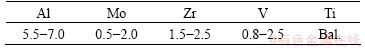
Table 2 Chemical compositions of 304 stainless steel (mass fraction, %)
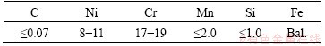
Table 3 Physical properties of base metals at room temperature
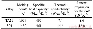
In Table 3, large differences in thermal conductivity and linear expansion coefficient between the two base metals can be found. These will lead to large temperature gradients and thermal stresses in the joint during the welding process [14]. The metals were machined into 50 mm �� 25 mm �� 2.5 mm plates and then mechanically and chemically cleaned before welding. 0.5 mm thick commercially pure vanadium, nickel, and copper sheets were used as filler metals and embedded in the contact faces before welding as BARREDA et al [15] did in their research.
2.2 Welding process
Electron beam welding was used to join titanium alloy to stainless steel. Electron beams were focused on the centerlines of the filler metal sheets with the following parameters: accelerating voltage of 55 kV, focus current of 2450 mA, welding speed of 6 mm/s and beam current of 9-12 mA. A schematic diagram of the welding procedure is shown in Fig. 1.
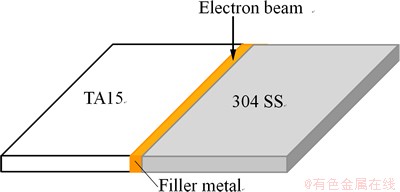
Fig. 1 Schematic diagram of welding procedure
2.3 Test work
Specimens for microstructure characterization and hardness examination were prepared metallographically and then etched in a solution of 20 mL HNO3, 20 mL HF and 80 mL H2O. Microstructure observations on cross-sections of the joints were carried out by optical microscopy and scanning electron microscopy. The elemental composition was evaluated by SEM-EDS in spot and line scan modes. X-ray diffraction analysis was carried out to identify the intermetallics. The operating voltage was 50 kV and the current was 25 mA using a Cu target. The scanning range was 20��-100�� at a speed of 3 (��)/min. Vickers microhardness was measured using a load of 100 g. Tensile testing at room temperature was performed to evaluate the joint strength. The specimens were prepared in rectangular bars (50 mm �� 5 mm �� 2.5 mm). The displacement speed was 0.5 mm/min.
3 Results and discussion
3.1 Microstructures of joint cross sections
3.1.1 Macrostructures of cross sections
Figure 2 shows the cross-section macrostructures of the electron beam welded Ti/steel joint with and without Ni, V, Cu filler metals. Sound joint could not be achieved without filler metal and with V filler metal due to the through crack propagation at the interface between Ti alloy and the weld. Low melting point Cu filler metal melted completely, while partial V and Ni filler residual in the weld because of their high melting points.
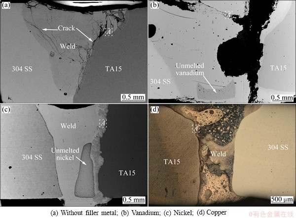
Fig. 2 Macrostructures of cross sections of joints with different filler metals
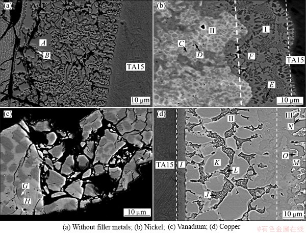
Fig. 3 Microstructures of Ti side interfaces of Ti/steel joints with different filler metals in zone A
3.1.2 Microstructures of interfaces between TA15 and welds
Ti is an active element and tends to form intermetallics with multiple metal elements. Hence, microstructures of the Ti side interface was analyzed and comparatively studied. The microstructures of the Ti side interfaces of the Ti/steel joints are shown in Fig. 3. The constituent phases of the interfaces were analyzed combined with EDS analysis (Table 4).
Table 4 Chemical compositions of different phases (mole fraction, %)
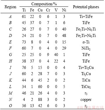
A lot of dense cracks form around the through crack in the Ti side interface which is constituted by dispersive blocky phase A and continuous network distributed phase B without filler metals. From Table 4 and the Ti-side of Ti-Fe binary phase diagram (Fig. 4(a)) [16], Phases A and B can be identified as Ti+TiFe and TiFe. It can be seen that cracks primarily appeared in TiFe phase.
The Ti side weld is divided into two morphologically marked distinct zones with Ni filler metal, which are denoted by zone I and zone II. Combined with Ti-Ni-Fe ternary phase diagram (Fig. 5(a)) [17] and Ni-Ti binary phase diagram (Fig. 5(b)) [18], zone II, which is located in the triple-phase region, is the mixture of (��-Fe, Ni) solid solution, Fe2Ti and Ni3Ti (Phases C and D). Zone I is mainly composed of Ni2Ti (Phase F), with a small amount of ��-Ti (Phase E) dispersed around it. Figure 6(a) shows the XRD analysis result which confirmed the above phases.
The Ti-Fe-V ternary phase diagram (Fig. 4(b)) shows that there is no ternary intermetallic compound among Ti, Fe and V elements [19]. The solid solubility of V in TiFe is rather low. Combined with the EDS results, it can be anticipated that phase G and phase H are TiFe with different supersaturated V element content, considering that the V content in those phases is higher than the solid solubility, which were formed during the rapid cooling of electron beam welding.
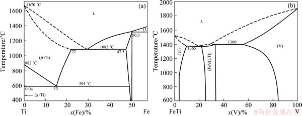
Fig. 4 Ti side of Ti-Fe binary phase diagram (a) and TiFe-V ternary phase diagram (b)
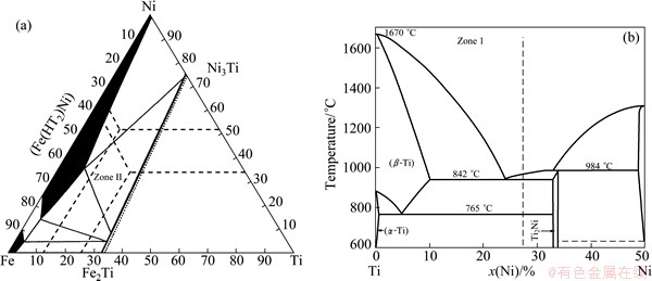
Fig. 5 Ti-Fe-Ni ternary phase diagram at 293 K (a) and Ti side of Ti-Ni binary phase diagram (b)
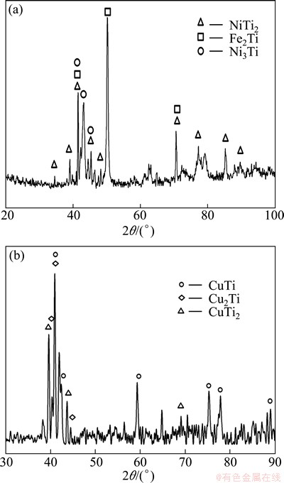
Fig. 6 XRD patterns of Ti side interface zone with Ni filler metal (a) and with Cu filler metal (b)
Microstructure in weld near titanium alloy with Cu filler metal is shown in Fig. 3(d). This region is divided into three zones according to their morphology characteristics, and they are marked as zones I, II and III respectively. From the EDS results as well as Ti-Cu-Fe phase diagram [17] (Fig. 7), zone I consists of solid solution of titanium with some Ti2Cu in it (phase I). Zone II is characterized by blocky compounds Ti2Cu (phase J) and TiCu (phase K) as well as dispersedly distributed fine TiCu2 (phase L). It needs to notice that Cu2Ti is a kind of metastable phase existing in the temperature range of 890-870 ��C. But it was retained at room temperature in this joint for the high cooling rate during electron beam welding. Zone III contains 3 phases. It is made up of dark grey Ti43Cu57-xFe (x=21-24) blocks denoted as ��3 ( phase M), with the same lattice type as Cu4Ti3, light grey phase Ti40Cu60-xFe (x=5-17) denoted as ��2 (phase O) ,with the same lattice type as Cu3Ti2 and solid solution of copper (phase N). The above anticipated phases were confirmed by XRD analysis (Fig. 6(b)).
From the analysis presented above, the Ti side welds are composed of intermetallic compounds. And the constitution of the compounds, which causes the different properties of the weld joints, are determined by the metallurgy reactions between the filler metals and the base metals. When a filler metal is used, new interfacial componds replace the TiFe phase in Ti/Fe joint. Obviously, toughnesses of Ti-Ni or Ti-Cu interfical compounds are higher than those of Ti-Fe intermetallics.
3.2 Mechanical properties of joints
3.2.1 Microhardnesses of interface zones
The average microhardness of the each intermetallic layer was measured to compare the properties of the different interface compound layers. The result is shown in Fig. 8.
The super-saturated Ti-Fe compound layer obtained with the V filler metal shows the highest microhardness, even higher than Ti-Fe compound. The hardness of Ni-Ti compound layer is relatively lower. While Ti-Cu intermetallics is the softest. Refering to Fig. 2, crack occurs in the joint when the hardness of the interfacial compund layer is higher than HV 1000.
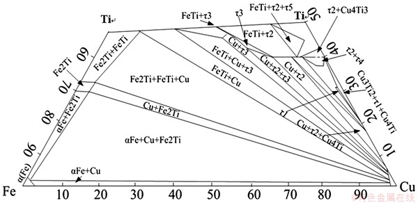
Fig. 7 Partial isothermal section of Ti-Fe-Cu ternary phase diagram at room temperature
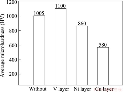
Fig. 8 Comparison of average microhardness of each intermetallic layer
Table 5 Tensile strength of electron beam welded Ti/steel joints with different filler metals
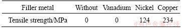
3.2.2 Tensile strengths of joints
The tensile strength of the electron beam welded Ti/steel joints with different filler metals are listed in Table 5. The results indicate that the tensile strength is related to average hardness of the interface compound layer. The tensile strength increases with the decrease of average hardness of the interface compound layer. The property of the joint is mainly determined by the property of the compound layer, especially toughness of the layer. This is because the crack arrest property is fine and the tensile strength is high when the toughness of the compound layer is good. The crack arrest property is poor and might even crack after welding when the toughness of the compound layer was low.
Combining the above analysis, the basic selecting method of the filler metal can be concluded. The interfacial intermetallics in the joint welded using a filler metal must have good toughness and crack arrest property. Not only the binary reactions, but also the ternary reactions among the filler metal and base metals need to be considered. From this experiment, copper is a good candidate of the filler metal for the electron beam welding of titanium alloy to stainless steel. Firstly, Ti-Cu intermetallics have relatively lower hardness. Secondly, copper is a soft metal, which can deform easily to reduce the inner stress during electron beam welding.
4 Conclusions
1) Direct electron beam welding of Ti/Fe joint failed for the formation of continuously distributed Ti-Fe intermetallics. Lots of solid solution formed in the weld for the adoption of filler metals. The interfacial intermetallics were changed to Fe2Ti+Ni3Ti+NiTi2, TiFe, and Cu2Ti+CuTi+CuTi2 in the joints welded with Ni, V, and Cu filler metals, respectively. Among the filler metals, throughout cracking occurred in the joint with V filler metal.
2) The tensile strength was related to average hardness of the interface compound layer. The joint with good toughness was benefit to the elevation of the joint strength. The microhardness value order of the joint was V, Ni, Cu from high to low order, while the tensile strength order of the joint was opposite. Of all, the highest tensile strength was obtained in the joint welded with copper filler metal, which is about 234 MPa.
3) The influences of filler metals on the electron beam weld ability of Ti/Fe joint were primarily based on the reaction products and its hardness. The hardness of the interfacial compounds higher than HV1000, sound joint can not been achieved. When the hardness decreased to about HV 860, cracks in the joint was eliminated.
References
[1] BOYER R R. An overview on the use of titanium in the aerospace industry [J]. Materials Science and Engineering A, 1996, 213: 103-114.
[2] YANG J L, LI Y, WANG F. New application of stainless steel [J]. Journal of Iron and Steel Research, International, 2006, 13: 62-66.
[3] SUDHA C, PRASANTHI T N, MURUGESAN S. Study of interface and base metal microstructures in explosive clad joint of Ti�C5Ta�C1.8Nb and 304L stainless steel [J]. Science and Technology of Welding and Joining, 2011, 16: 133-139.
[4] KUNDU S, SAM S, CHATTERJEE S. Interface microstructure and strength properties of Ti�C6Al�C4V and microduplex stainless steel diffusion bonded joints [J]. Materials and Design, 2011, 32: 2997-3003.
[5] DEY H C, ASHFAQ M, BHADURI A K AND RAO K P. Joining of titanium to 304L stainless steel by friction welding [J]. Journal of Materials Processing Technology, 2009, 209: 5862-5870.
[6] MOUSAVI S A A A, SARTANGI P F. Experimental investigation of explosive welding of cp-titanium/AISI 304 stainless steel [J]. Materials and Design, 2009, 30: 459-468.
[7] KUNDU S, CHATTERJEE S. Characterization of diffusion bonded joint between titanium and 304 stainless steel using a Ni interlayer [J]. Materials Characterization, 2008, 59: 631-637.
[8] ELREFAEY A, TILLMANN W. Solid state diffusion bonding of titanium to steel using a copper base alloy as interlayer [J]. Journal of Materials Processing Technology, 2009, 209: 2746-2752.
[9] HE P, YUE X, ZHANG J H. Hot pressing diffusion bonding of a titanium alloy to a stainless steel with an aluminum alloy interlayer [J]. Materials Science and Engineering A, 2008, 486(1-2): 171-176.
[10] GAO M, MEI S W, WANG Z M. Characterisation of laser welded dissimilar Ti/steel joint using Mg interlayer [J]. Science and Technology of Welding and Joining, 2012, 17: 269-276.
[11] SUN Z, KARPPI R. The application of electron beam welding for the joining of dissimilar metals: An overview [J]. Journal of Materials Processing Technology, 1996, 59: 257-267.
[12] ZHANG H T, HE P, FENG J C, WU H Q. Interfacial microstructure and strength of the dissimilar joint Ti3Al/TC4 welded by the electron beam process [J]. Materials Science and Engineering A, 2006, 425: 255-259.
[13] KIM J H, KAWAMURA Y. Electron beam welding of Zr-based BMG/Ni joints: Effect of beam irradiation position on mechanical and microstructural properties [J]. Journal of Materials Processing Technology, 2008, 207: 112-117.
[14] WEI Y H, DONG Z B AND LIU B. Stress distributions of welding joints in titanium�Csteel composite pressure vessel under working conditions [J]. Science and Technology of Welding and Joining, 2011, 16: 709-716.
[15] BARREDA J L, SANTAMARIA F, AZPIROZ X. Electron beam welded high thickness Ti6Al4V plates using filler metal of similar and different composition to the base plate [J]. Vacuum, 2001, 62: 143-150.
[16] OKAMOTO H. Fe-Ti(Iron-titanium) [J]. Journal of Phase Equilibrium, 1996, 17(4): 369.
[17] VILLARS P, ALAN PRINCE, HIROAKI OKAMOT. Handbook of ternary alloy phase diagrams [M]. ASM International, 1995: 5646.
[18] MURRAY J L. Ni-Ti(Nickel-Titanium) [J]. Phase diagrams of Binary Nickel Alloys, 1991.
[19] RAGHAVAN V. Fe-Ti-V (Iron-Titanium-Vanadium) [J]. Journal of Phase Equilibrium, 1993, 14(5): 632.
���������ѺϽ��벻��ֵ��������ӵ�Ӱ��
�� ͢1���ű���2���뼪��1,2
1. ��������ҵ��ѧ(����) ɽ��ʡ���ֺ����ص�ʵ���ң����� 264209��
2. ��������ҵ��ѧ �Ƚ����������ӹ����ص�ʵ���ң������� 150001
ժ Ҫ������Ni��V��Cu�������Ͻ����ѺϽ��벻��ֵĵ���������ʵ�顣���ù�ѧ������ɨ��羵��X��������Խ�ͷ������֯���з�����ͨ������ǿ�Ⱥ���Ӳ�����۽�ͷ����ѧ���ܣ��������������϶���/�ֵ��������ӽ�ͷ����֯����ѧ���ܵ�Ӱ�졣�������������������������Ti-Fe�����仯����IJ��������н�ͷ���ɹ�����ͽ��滯������ɡ����ڲ�ͬ�������ϣ�������ͽ��滯��������ȡ������������ĸ��֮���ұ��Ӧ������Ni��V��Cu�����ϣ����滯����ֱ�ΪFe2Ti+Ni3Ti+NiTi2, TiFe�� Cu2Ti+CuTi+CuTi2����ͷ����ǿ����Ҫȡ���ڽ����仯����Ĵ��ԡ�����Cu�������Ľ�ͷ����ǿ����ߣ�ԼΪ234 MPa��
�ؼ��ʣ��ѺϽ𣻲���֣������������������ӣ���ѧ����
(Edited by Chao WANG)
Foundation item: Project (2011DFR50760) supported by International Science & Technology Cooperation Program of China
Corresponding author: Bing-gang ZHANG; Tel: +86-451-86412911; E-mail: zhangbg@hit.edu.cn
DOI: 10.1016/S1003-6326(14)63034-X

