Trans. Nonferrous Met. Soc. China 24(2014) 3060-3069
Microstructural evolution and delayed hydride cracking of FSW-AZ31 magnesium alloy during SSRT
Rong-chang ZENG1,2, Wolfgang DIETZEL2, Rudolf ZETTLER2, Wei-min GAN2, Xin-xin SUN1
1. College of Material Science and Engineering, Shandong University of Science and Technology, Qingdao 266590, China;
2. Institute of Materials Research, Helmholtz-Zentrum Geesthacht, Geesthacht 21502, Germany
Received 31 December 2013; accepted 6 June 2014
Abstract: Evolution of microstructure including texture and fractography in a friction-stir welded (FSW) AZ31 magnesium alloy was investigated. The texture was measured using a neutron diffractometer. The microstructure and fractography of stress corrosion cracking (SCC) samples were observed by optical and scanning electron microscopy, respectively. An X-ray diffraction study was carried out on the fractured surfaces of the SCC specimens. The results indicated that a strong basal fiber was formed on the base material, whereas the grains in the stir zone were reoriented with their most basal planes tilted 25�� to the welding direction. Feather-like twins and hydride formed under slow strain rate tensile (SSRT) stress in air and aggressive solutions, respectively. Transgranular cracks propagated and finally failed on the retreating side in the solution. The hydride phase confirmed to sit on the fracture surface demonstrated the delayed hydride cracking (DHC) mechanism of the alloy.
Key words: magnesium alloys; stress corrosion cracking; friction stir welding; texture; microstructure
1 Introduction
Mg alloys are prime candidates for use in the transportation and aerospace industries due to their lightness and high specific strength. Consequently, welding and joining procedures for integrated components using these materials will be required [1-3]. Conventional fusion welding methods such as electron beam and inert gas arc welding have been shown to produce porosities in welded Mg alloys [4]. These deteriorate the mechanical properties of the joint. Friction stir welding, however, easily provides defect-free welds with fine grain structure and minimized distortion [3-5]. Like all welding processes, however, friction stir welding does cause a change in the original microstructure as a consequence of mechanical deformation and thermal cycling during the joining process.
Microstructural evolution including dynamically re-crystallized, equiaxed grains with a high density of dislocations has been shown to occur in the weld nugget of a FSW AZ31 alloy [6]. Further investigations [7-10] on FSW magnesium alloys, such as AZ31B, AZ61, AM60 and ZK60 as well as Mg-2.0Na-0.3Zn-1.0Zr, reveal a micro-texture change from the base material (BM) to the stir zone (SZ) with results dependent upon processing parameters applied. WOO et al [11] suggested that shear plastic flow during friction stir processing caused approximately 90�� rotation of the basal plane near the processing zone, so that its normal is parallel to the transverse direction (TD) in the transition zone (TZ) of the joint. Nevertheless, dynamic recrystallization in the SZ gives rise to a new texture, in which the basal plane is roughly normal to the rotating pin surface [6]. Moreover, XIE et al [2] claimed that the relatively weak basal texture occurred in the nugget zone on the TD compared with the BM and the basal planes were around the pin. However, ZHANG et al [10] found that (0002) basal planes of Mg tend to be arranged parallel to the plate surface on the top and bottom surfaces of the SZ. No obvious texture had evolved and (0002) basal planes distributed randomly in the cross section of the SZ. This conjecture makes clear that further investigation is required if the nature of texture formation in FSW Mg alloys is to be fully understood.
The texture of the magnesium alloy can be influenced as a result of severe plastic deformation [12], where alloying elements [13], annealing processing [14] and plastic processing [13,15] all play their parts. It has been reported that the texture of magnesium alloys has a significant influence on the mechanical properties after equal channel angular processing (ECAP) [16], FSW [6] and friction-stir processing (FSP) [11]. However, the influence of texture on the stress corrosion behavior of FSW magnesium alloys remains unclear [17].
The AZ31 alloy is one of the most popular wrought magnesium alloys, and usually supplied as sheet materials with small thickness. The processing technology and mechanical properties of this type of magnesium alloy has been extensively investigated [10,12].
Since the in-service Mg components of automobiles are inevitably subjected to load or stress, fatigue failure and stress corrosion cracking may occur. Thus, it is of significant scientific and practical interest to study the mechanism of fatigue failure and stress corrosion cracking (SCC) of magnesium alloys [18,19]. Our previous study [20,21] demonstrated that the fatigue failure of as-extruded AZ alloys is influenced by the microstructural factors (i.e., grain size, intermetallic compounds), loading factors and environmental factors. LUO et al [22] observed that fatigue failure occurred at the stir zone of the FSW AZ31 sheet joints, and cracks initiated at the stir zone outer edge.
Also, Mg alloys are susceptible to SCC in chloride- containing solutions and some even in distilled water [18,23]. A considerable amount of work has been done on the SCC behavior of AZ series alloys [24-26]. KANNAN and DIETZEL [27] demonstrated that pitting corrosion facilitated hydrogen into AZ80 alloy and caused hydrogen embrittlement. RAJA and PADEKAR [28] investigated the interrelation among chlorides- pitting-hydrogen evolution and hydrogen embrittlement. ARGADE et al [29] found that higher SCC susceptibility of friction stir processed ultrafine grained AZ31 is attributed to increased hydrogen adsorption and favorable basal texture. It is generally accepted that the mechanism for transgranular SCC (TGSCC) of Mg alloys is a form of hydrogen embrittlement (HE) [19]. The HE models [23,30-33] include hydrogen enhanced decohesion (HEDE), hydrogen enhanced localized plasticity (HELP), adsorption-induced dislocation emission (AIDE), and delayed hydride cracking (DHC). WINZER et al [32] proposed a model of the DHC mechanism for transgranular stress corrosion cracking of magnesium alloys using a finite element script developed in MATLAB. The mechanism for SCC initiation in AZ31 remains unknown [23].
SRINIVASAN et al [34] claimed that the stress corrosion cracks originate in the weld metal and propagate through the weld metal-HAZ regions in the autogenous weldment. To date, no direct proofs have been reported to support the DHC mechanism of Mg alloys.
The motivation of the present study is to clarify the texture modification in the weld of FSW-AZ31 as influenced by slow strain rate tensile (SSRT) testing in air and corrosive solutions, and to have a further insight into the DHC mechanism of this alloy
2 Experimental
2.1 Materials
The materials used were AZ31 alloy sheets with a plate thickness of 1.9 mm. Friction stir welding was performed on Helmholtz-Zentrum Geesthacht in Germany, using a Tricept TR805 Robot. Figure 1 shows a schematic diagram of the friction stir weldment and the positions for texture measurement.
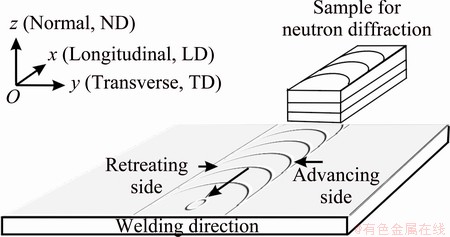
Fig. 1 Schematic diagram of friction stir welding and texture analysis points
2.2 Microstructure examination
Weld joints were sectioned and prepared using standard metallographic procedures. The specimens were etched in a solution containing 3.5 g picric acid, 6.5 mL acetic acid, 20 mL water and 100 mL ethanol. The microstructures of the FSW-AZ31 materials were examined with a Leica optical microscope. The grain size was measured using a linear intercept method according to ASTM E122-88. The average grain size was estimated by counting the number if grains intercepted by five straight lines are sufficiently long enough to yield at least 50 intercepts.
2.3 Texture measurement
Pieces with sizes of 10 mm��10 mm were cut from the center of the weld seam and the parent metal. Three pieces were then stacked to form a single sample. Here three complete pole figures: (0002),  and
and  were measured with a neutron diffractometer STRESS-SPEC (Garching, Germany); and the neutron beam diffraction direction was parallel to the extrusion or weld seam direction (LD in Fig. 1), the definition of the coordinate system. The texture evolution of the BM and FSW sample interrupted during the SSRT test in ASTM D1384 solutions (containing 148 mg/L Na2SO4, 165 mg/L NaCl and 138 mg/L NaHCO3) were conducted using an XRD instrument (Riguta D/max-RC) with a Cu K��1 (��=0.15406 nm) source operated at 35 V and 20 mA.
2.4 SCC tests
The slow strain rate tensile (SSRT) test method was used to evaluate the SCC susceptibility of the FSW AZ31 alloys. Gauge dimensions for flat tensile specimens measured were 24 mm��6 mm��1.8 mm. With regard to FSW tensile samples, the weld region was located at the middle of the gauge section. These samples were ground with SiC paper up to 2400 grit, and were then cleaned with acetone prior to testing. The samples were tested in ASTM D1384 solutions at strain rates of 10-7 s-1 and 10-8 s-1. In air the strain rate was 2��10-6 s-1. SCC susceptibility was then evaluated for mechanical properties such as elongation to failure (��f), reduction in area (RA) and ultimate tensile strength (UTS), measured in air or solution.
2.5 Surface observation and chemical analysis
The samples after the SSRT were taken out, and washed in water, then were observed with an optical microscope. The fracture surfaces were discerned with a scanning electron microscope (SEM, JSM-6460LV).
And the chemical compounds of the BM and FSW samples, interrupted during the SSRT test in ASTM D1384 solution at a strain rate of 10-7 s-1, were probed with an X-ray diffractometer (XRD, BDX3300 type).
3 Results
3.1 Susceptibility of SCC
Figure 2 shows the stress�Cstrain curves of the FSW AZ31 samples obtained from the SSRT tests in air and the corrosive solution, respectively. The FSW samples demonstrated drastic loss in ductility, including elongation to failure (��f) and reduction in area (RA), and ultimate tensile strength (UTS) in the corrosive environment (Table 1). In addition, the more significant decrease in strength with a lower strain rate implies that the FSW AZ31 is sensitive to SCC in the solution. It was also reported that similar loss in ductility and strength levels in FSW AZ31B and AZ61 alloys occurs [6,11]. It is noting that strain rate,  , has a remarkable impact on the SCC sensitivity of the alloy due to the different periods exposed to the solution.
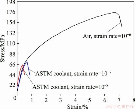
Fig. 2 Stress�Cstrain curves of FSW AZ31 Mg samples obtained from SSRT tests in air or in ASTM D1384 solutions
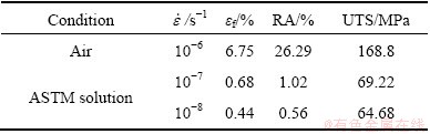
Table 1 Mechanical properties obtained from SSRT tests in corrosive environment and its corresponding value in air
3.2 Microstructural evolution
3.2.1 Microstructure of FSW AZ31
Figure 3 shows the cross-sectional view of the FSW AZ31 sample. The solid-state nature of the friction stir welding process results in a highly characteristic microstructure. The BM has a coarse microstructure (Fig. 4(a)), while the microstructure in the SZ of AZ31 is characterized by fine equiaxed grains (9.75 ��m) and AlMn intermetallic compounds, which appear as black dots in Fig. 4(b). Our prior study [35] designated that the AlMn intermetallic compounds extensively existed in extruded AZ31 alloy. The marks of SZ in Fig. 3 and Fig. 4(c) designate the deformation twins caused by the spin friction. These twins go through dozens of grains, and seem to have roughly same orientation direction.
The microstructures of BM, TMAZ and SZ feature equiaxed grains (Fig. 4), with grain size increasing in the following order: SZ (9.75 ��m)��TMAZ (9.89 ��m)��BM (12.0 ��m). More twins randomly occurred numerous orientation directions TMAZ due thermo-mechanical (Fig. 4(b)) friction stir welding process.
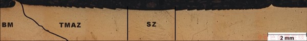
Fig. 3 Cross-sectional view of FSW AZ31 sample
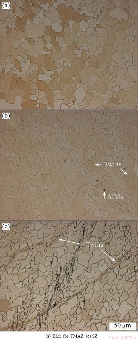
Fig. 4 Optical micrographs of FSW-AZ31 alloy
It is clear that the microstructure in SZ is characterized by the fine and equiaxed grains. This is attributed to dynamic recrystallization brought about by intense plastic deformation and thermal cycling during friction stir welding.
3.2.2 Microstructure after SSRT in air
In comparison to the microstructure in BM (Fig. 5(a)), a significant change in the microstructure appeared after SSRT test in either air or solutions. The microstructure after SSRT test in air demonstrates coarsened twins in the presence of feathers and secondary twins developed in the TMAZ (Fig. 5(b)) and SZ (Fig. 5(c)). Particularly, more and more grains tend to be parallel to the tensile direction. This is ascribed to grain rotation resulting from the tensile stress such that more grains have a favorable orientation for twinning. Preferred orientation is developed when the lattice of individual grains in polycrystalline material reorients themselves during plastic deformation. In the twinning grains, twinning was ignited such that a considerable amount of twins coalesced to form a colony of twins in the shape of feathers.
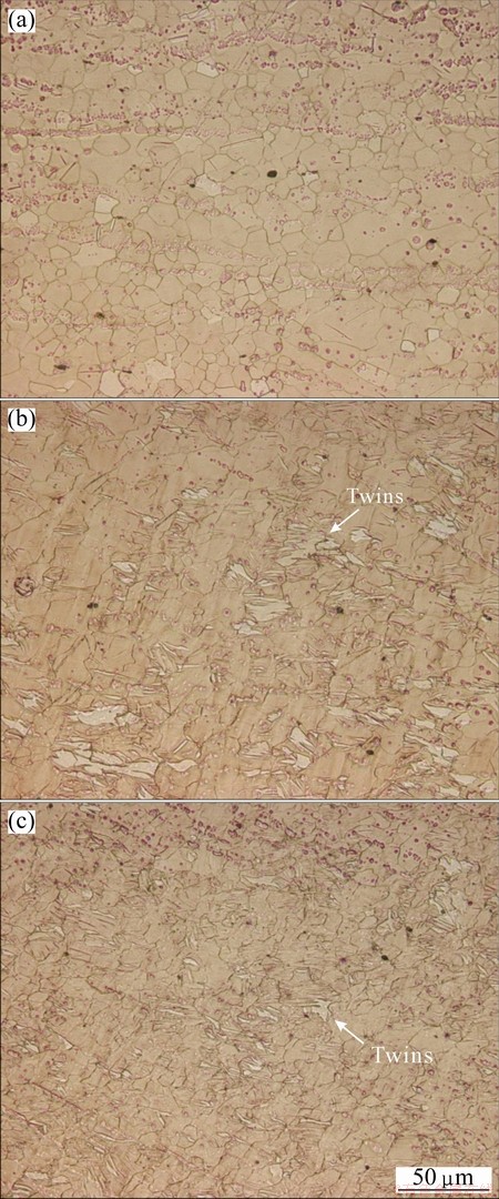
Fig. 5 SEM images for feather-like twins of BM (a), TMAZ (b) and SZ (c) after SSRT test in air
3.2.3 Microstructure after SSRT in solutions
A distinct evolution in the microstructure after the SSRT test in solutions is the occurrence of MgH2 hydride precipitation in TMAZ, as shown in Fig. 6. It was proposed that the hydride may form during SCC [30]. Compared with the microstructure in Fig. 6(a), the hydride is apparently distributed along the rolling direction in the BM and shear plastically deformed flow. It may be ascribed to the dense dislocations which trap high concentrations of hydrogen atoms in the TMAZ and SZ, and thus led to the formation of hydrides. Figure 6(c) reveals that transgranular cracks initiate and propagate along some crystallographic planes such as (0002) basal plane. This analogous phenomenon is also discerned during fatigue testing of magnesium alloys [36].
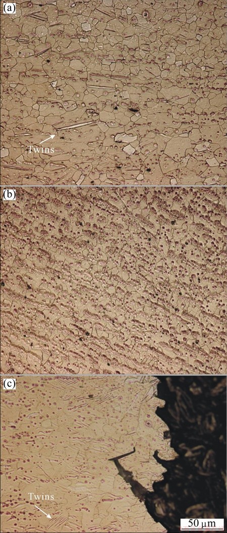
Fig. 6 SEM images of BM (a), TMAZ (b) and SZ (c) after SSRT test in ASTM D1384 solution
3.3 Texture after friction stir welding
Figure 7 shows the (0002) and measured complete pole figures of the AZ31 alloy before and after the friction stir welding, respectively. The base material is homogeneous and exhibits a basal fiber with the (0002) planes in most grains parallel to the longitudinal direction (LD) or welding direction (WD), which is a typical texture of hot-rolled Mg alloys. While the basal planes in most grains in the welding region tilted approximately 25�� to the LD or WD on the retreating side, resulting from the shear plastic flow during FSW.
The degree of the tilting angle of (0001) basal plane to the WD is different from the results from PARK et al [6] and WOO et al [11,12]. PARK et al [6] found that the (0001) plane of the FSW AZ61 alloy is roughly perpendicular to the WD in the weld center, and tilted about 45�� from the TD in the fracture region on the tensile sample. WOO et al [12] found that the basal plane normal is mainly parallel to the normal direction (ND) at BM/ HAZ, mostly parallel to the TD near the TZ and not parallel to either ND or TD in the SZ. These texture variations for the various materials are likely the results of the original BM texture, processing parameters, tool design and relative heat losses.
3.4 Texture after SSRT test
The XRD patterns of the BM and FSW after the SSRT test in the solution, as shown in Fig. 8, indicate that the BM is predominantly composed of ��-Mg, with a trace of MgO and MgH2. The basal plane (0002) of ��-Mg phases is the major direction of the texture, and with other crystallographic planes including (1010) and (1012), etc. The MgO originally came from the corrosion product Mg(OH)2. The formation of hydride MgH2 was attributed to the tensile stress and the evolved hydrogen reacted with magnesium during corrosion, and penetrated into the defect sites such as dislocations and twin boundaries. Amorphous compound MgCO3��Mg(OH)2�� 3H2O was also found.
The chemical reactions occurred as follows:
Anodic reaction:
Mg=Mg2++2e (1)
Cathodic reaction:
2H2O+2e=2OH-+H2�� (2)
Total reaction:
Mg+2H2O=Mg(OH)2+H2�� (3)
In ASTM D1384 solution, alkaline carbonate formed on the SCC sample surfaces.
2Mg2++CO3+2OH-+3H2O=MgCO3��Mg(OH)2��3H2O (4)
This demonstrates that basal plane (0002) prefers to re-orientate in the tension direction as a result of the SSRT test. Moreover, it implies that MgH2 plays a significant role in SCC of friction stir welded AZ31 alloy.
3.5 Fractography
Figure 9 depicts the macrographs of the sample just before it fully fractured in ASTM D1384 solution at a strain rate of 10-7s-1. Crack arrest was found in the samples. Interestingly, the macrographs reveal the multi-cracking of the samples on the retreating side and along the centre of the weld metals. This could be related to the deformation of twinned grains and their reorientation. This result is different from what AFRIN et al [7] observed where the friction stir welded joints failed mostly at the boundary between the weld nugget and TMAZ on the advancing side, while being tensile tested. The failure of the tensile samples suggested a 45�� shear fracture. The failure in the TMAZ could be explained by the grain growth and the presence of oxides on the fracture surface.
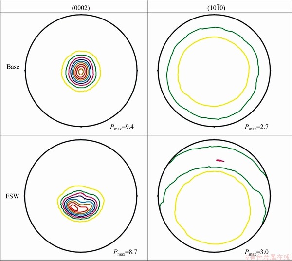
Fig. 7 Measured complete (0002) and  pole figures of AZ31 alloy before and after FSW (counter level =1.0��, 2.0����)
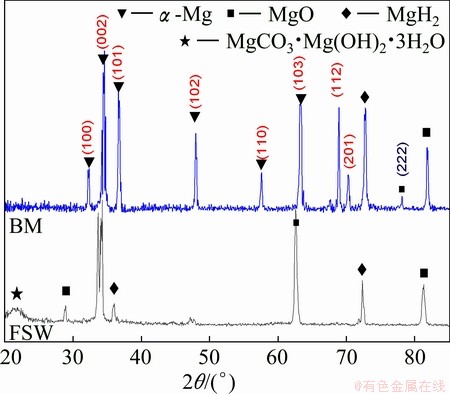
Fig. 8 XRD patterns of BM and FSW sample interrupted during SSRT test in ASTM D1384 solution at strain rate of 10-7s-1
Moreover, similar crack arrest was observed on the sample at a strain rate of 10-8s-1, as shown in Figs. 10(a) and (b). The SCC cracks may nucleate on twinning planes such as and
and  [34] (Fig. 10(c)).
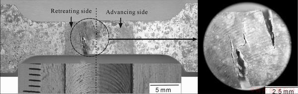
Fig. 9 SCC macro-cracks of AZ31 sample in ASTM D1384 solution at strain rate of 10-7s-1
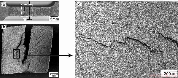
Fig. 10 Macrograph of SCC sample at strain rate of 10-8s-1 (SCC cracks nucleated at the twinning planes)
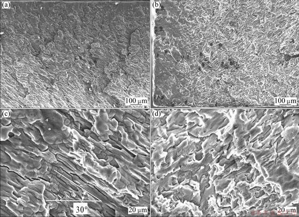
Fig. 11 Lower magnification SEM images (a, b) of SCC fractured samples in air at strain rate of 10-6s-1 (a) and in ASTM solution at strain rate of 10-7s-1 (b), and higher magnification images (c, d) of (a) and (b), respectively
Figures 11(a) and (b) designate the lower magnification SEM images of a pair of SCC fracture samples in the ASTM solution at the strain rate of 10-7 s-1. The fracture surfaces of the exposed FSW-AZ31 specimen exhibit fluted structures with macroscopically flat areas, cleavage-like facets and secondary cracks, showing a characteristics of brittle rupture in the coolant solution (Figs. 11(c) and (d)). The distance between consecutive flutes was several macrons and there were no interconnecting ligaments. The areas were generally parallel and oriented towards the direction tilted roughly 30�� to the WD. This angle is very close to the 25�� tilt angle between the basal plane and TD, measured via neutron diffraction for the texture in SZ. Similar result was observed on Zr-2.5%Nb pressure tube during SCC testing, a change in the orientation of the ��-zirconium grains, mainly by twinning on the planes [37].
4 Discussion
When the specimen is loaded in uniaxial tension, the critical resolved shear stress on any given plane is determined by
 (5)
(5)
where ��s is yielding strength, �� is the angle between the plane normal and the applied stress, and �� is the angle between the slip direction and the applied stress.
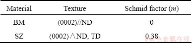
The Schmid factor, m=cos�ա�cosl, is defined as the ratio of the resolved shear stress to the axial stress. For magnesium alloy, the slip plane is the basal plane (0002) at room temperature. Based on the analysis of neutron diffraction, m for the dominant texture in the FSW AZ31 alloy is listed in Table 2. The dominant m is zero for the base materials and 0.38 for the SZ, respectively. Yielding occurs by dislocation slip when the resolved shear stress on one of the planes exceeds a critical value, ��c.
Table 2 Dominant texture of BM and SZ of FSW
Since the yielding strength of the FSW AZ31 alloy is 82.9 MPa, then at the texture tilted 25�� of (0001) basal plane to the welding direction,
 (6)
(6)
Equation (6) indicates that slip appears on the basal plane (0002) in the FSW AZ31 sample as the tension stress is not less than 31.8 MPa.
It is well-known [36] that the dominant deformation mechanisms in magnesium are basal slip, secondary (prismatic and pyramidal) slip, and  tension twinning and compression twinning. ZENG et al [36] claimed that basal slip occurred first at a stress ~0.5 MPa, followed by tension twinning and secondary slip. Therefore, in this case, tension twinning is the other particularly important cause of crack nucleation in coarse-grained magnesium alloys.
The secondary cracks on the fracture surface of the FSW sample (Fig. 10) are indicative of hydrogen embrittlement failure of the material. Our previous results [17] showed a higher uniform and pitting corrosion resistance for the SZ compared with the base material. It was reported that the SZ usually exhibits higher dislocation density than the base material [6]. This high dislocation density in SZ can accelerate the hydrogen embrittlement susceptibility of AZ31 Mg alloys [16]. However, based on the microstructural observation on the sample after SSRT tests, it is mostly like that the DHC could be a reason for the higher SCC susceptibility of the FSW AZ31 Mg samples.
Magnesium hydride can be formed by the following three electrochemical cathodic reactions [33]:
Mg2++H2+2e=MgH2 (7)
Mg2++2H++4e=MgH2 (8)
Mg+2H++2e=MgH2 (9)
In electrodynamics, MgH2 is not a stable compound and could be easily decomposed.
MgH2=Mg2++H2+2e (10)
MgH2 was observed according to the results of XRD in Fig. 8. Also, it has been demonstrated that the magnesium hydride (MgH2) formed in the cathodic region and decomposed in the anodic region [33].
DHC has been proposed as the mechanism for TGSCC of Mg alloys [30-32]. DHC involves repeated stages of: 1) stress-assisted diffusion of H to the region ahead of the crack tip; 2) hydride precipitation as the local H concentration exceeding the local solvus; and 3) brittle fracture through the hydride.
It was reported that lower stress rates would result in higher H-activity at the crack tip [32]. This manifests crack propagation along cleavage planes (i.e., twinning plane), grain boundaries or particle-matrix interfaces. The cleavage fracture surfaces observed in AZ91 alloy in 5 g/L NaCl solution were characteristics of stress-induced hydride formation, which involves stress-directed diffusion of H towards the crack tip, resulting in repeated formation and fracture of insoluble brittle hydrides [31]. MELETIS and HOCHMAN [38] claimed that the presence of cleavage in pure magnesium indicates the reduction in the surface energy of {2203} planes by hydrogen embrittlement resulting from preferential hydrogen accumulation or hydride formation on these planes [19]. Similarly, the DHC mechanism is also the SCC mechanism for Zr-2.5%Nb alloy [37]. The metals, including Mg and Zr, are prone to form hydrides [39]. The fracture proceeds by hydride formation in the stress concentrated region at the crack tip, cracking of the hydride, crack arrest (see Figs. 9 and 10) at the hydride-matrix interface and a cyclic repetition of the above events [40]. Therefore, DHC is the SCC mechanism of the FSW AZ31 alloy.
5 Conclusions
1) The microstructure of the FSW AZ31 alloy features equiaxed grains, with grain size increasing in the following order: SZ (9.75 ��m) 2) The base material is homogeneous and has a fiber texture with the (0001) plane perpendicular to the ND, whereas the basal planes in the welding region are tilted at approximately 25�� to the longitudinal direction or welding direction on the retreating side, due to the shear plastic flow during FSW.
3) Feather-like twins and hydride form under slow strain rate tensile stress in air and aggressive solutions. The re-orientation of basal plane (0002) during SSRT tests leads to multi-crack initiation of the FSW samples on the retreating side along the centre of the weld metals. Delayed hydride cracking might be the major reason for the higher SCC susceptibility of the FSW AZ31 Mg samples to the solution compared with the base material.
References
[1] CAO X, JAHAZI M. Effect of welding speed on the quality of friction stir welded butt joints of a magnesium alloy [J]. Materials Design, 2009, 30(6): 2033-2042.
[2] XIE G M, MA Z Y, GENG L. Effect of microstructural evolution on mechanical properties of friction stir welded ZK60 alloy [J]. Materials Science and Engineering A, 2008, 486(1-2): 49-55.
[3] ZENG R C, DIETZEL W, ZETTLER R, CHEN J, KAINER K U. Microstructure evolution and tensile properties of friction-stir-welded AM50 magnesium alloy [J]. Transactions of Nonferrous Metals Society of China, 2008, 18(S): s76-s80.
[4] ZETTLER R, BLANCO A C, DOS SANTOS J F, MARYA S. The effect of process parameters and tool geometry on thermal field development and weld formation in friction stir welding of the alloys AZ31 and AZ61 [C]//NEELAMEGGHAM N R, DAPLAN H I, POWELL B R. Magnesium Technology 2005. San Francisco: TMS, 2005: 409-423.
[5] CHOWDHURY S M, CHEN D L, BHOLE S D, CAO X. Tensile properties of a friction stir welded magnesium alloy: Effect of pin tool thread orientation and weld pitch [J]. Materials Science and Engineering A, 2010, 527(21-22): 6064-6075.
[6] PARK S H C, SATO Y S, KOKAWA H. Effect of micro-texture on fracture location in friction stir weld of Mg alloy AZ61 during tensile test [J]. Scripta Materials, 2003, 49(2): 161-166.
[7] AFRIN N, CHEN D L, CAO X, JAHAZI M. Microstructure and tensile properties of friction stir welded AZ31B magnesium alloy [J]. Materials Science and Engineering A, 2008, 472(1-2): 179-186.
[8] YIN Y H, IKUTA A, NORTH T H. Microstructural features and mechanical properties of AM60 and AZ31 friction stir spot welds[J]. Materials Design, 2010, 31(10): 4764-4776.
[9] WANG Y N, CHANG C I, LEE C J, LIN H K, HUANG J C. Texture and weak grain size dependence in friction stir processed Mg-Al-Zn alloy [J]. Scripta Materials, 2006, 55(7): 637-640.
[10] ZHANG D T, SUZUKI M, MARUYAMA K. Study on the texture of a friction stir welded Mg-Al-Ca alloy [J]. Acta Metallurgica Sinica: English Letter, 2006, 19(5): 335-340.
[11] WOO W, CHOO H, BROWN D W, LIAW P K, FENG Z. Texture variation and its influence on the tensile behavior of a friction-stir processed magnesium alloy [J]. Scripta Materials, 2006, 54(11): 1859-1864.
[12] WOO W, CHOO H, PRIME M B, FENG Z, CLAUSEN B. Microstructure, texture and residual stress in a friction-stir-processed AZ31B magnesium alloy [J]. Acta Materials, 2008, 56: 1701-1711.
[13] YAN H, CHEN R, ZHENG N, LUO J, KAMADO S, HAN E. Effects of trace Gd concentration on texture and mechanical properties ofhot-rolled Mg-2Zn-xGd sheets [J]. Journal of Magnesium and Alloys, 2013, 1(1): 23-30.
[14] ZHENG F Y, WU Y J, PENG LM, LI X W, FU P H, DING W J. Microstructures and mechanical properties of friction stir processed Mg-2.0Nd-0.3Zn-1.0Zr magnesium alloy [J]. Journal of Magnesium and Alloys, 2013, 1(2): 122-127.
[15] MAO P L, YU J C, LIU Z, DONG Y. Microstructure evolution of extruded Mg-Gd-Y magnesium alloy under dynamic compression [J]. Journal of Magnesium and Alloys, 2013, 1(1): 64-75.
[16] AGNEW S R, HORTON J A, LILLO T M, BROWN D W. Enhanced ductility in strongly textured magnesium produced by equal channel angular (ECA) processing [J]. Scripta Materials, 2004, 50(3): 377-381.
[17] ZENG R C, CHEN J, DIETZEL W, ZETTLER R, DOS SANTOS J F, NASCIMENTO M L, KAINER K U. Corrosion of friction stir welded magnesium alloy AM50 [J]. Corrosion Science, 2009, 51(8): 1738-1746.
[18] WINZER N, ATRENS A, SONG G, GHALI E, DIETZEL W, KAINER K U, HORT N, BLAWERT C. A critical review of the stress corrosion cracking (SCC) of magnesium alloys [J]. Advanced Engineering Materials, 2005, 7(8): 659-693.
[19] KANNAN M B, DIETZEL W, ZENG R, ZETTLER R, DOS SANTOS J F. A study of the SCC susceptibility of friction stir welded AZ31 Mg sheet [J]. Materials Science and Engineering A, 2007, 460-461: 243-250.
[20] ZENG R C, HAN E H, KE W. A critical discussion on influence of loading frequency on fatigue crack propagation behavior for extruded Mg-Al-Zn alloys [J]. International Journal of Fatigue, 2012, 36(1): 40-46.
[21] ZENG R C, HAN E H, KE W. Fatigue and corrosion fatigue of magnesium alloys [J]. Material Science Forum, 2005, 488-489: 721-724.
[22] LUO T J, SHI B L, DUAN Q Q, FU J W, YANG Y S. Fatigue behavior of friction stir spot welded AZ31 Mg alloy sheet joints [J]. Transactions of Nonferrous Metals Society of China, 2013, 23(7): 1949-1956.
[23] WINZER N, ATRENS A, DIETZEL W, RAJA V S, SONG G, KAINER K U. Characterisation of stress corrosion cracking (SCC) of Mg-Al alloys[J]. Materials Science and Engineering A, 2008, 488(1-2): 339-351.
[24] SONG R G, BLAWERT C, DIETZEL W, ATRENS A. A study on stress corrosion cracking and hydrogen embrittlement of AZ31 magnesium alloy [J]. Materials Science and Engineering A, 2005, 399: 308-317.
[25] CHAKRAPANI D G, PUGH E N. On the fractography of transgranular stress corrosion failures in a Mg-Al alloy [J]. Corrosion, 1975, 31(7): 247-252.
[26] WEARMOUTH W R, DEAN G P, PARKINS R N. Role of stress in the stress corrosion cracking of a Mg-Al alloy [J]. Corrosion, 1979, 29(6): 251-258.
[27] KANNAN M B, DIETZEL W. Pitting-induced hydrogen embrittlement of magnesium�Caluminium alloy [J]. Materials Design, 2012, 42: 321-326.
[28] RAJA V S, PADEKAR B S. Role of chlorides on pitting and hydrogen embrittlement of Mg-Mn wrought alloy [J]. Corrosion Science, 2013, 75: 176-183.
[29] ARGADE G R, YUAN W, KANDASAMY K, MISHRA R S. Stress corrosion cracking susceptibility of ultrafine grained AZ31 [J]. J Mater Sci, 2012, 47(19): 6812-6822.
[30] WINZER N, ATRENS A, DIETZEL W, SONG G, KAINER K U. Magnesium stress corrosion cracking [J]. Transactions of Nonferrous Metals Society of China, 2007, 17(S): s150-s155.
[31] MAKAR G L, KRUGER J, SIERADZKI K. Stress corrosion cracking of rapidly solidified magnesium-aluminum alloys [J]. Corrosion Science, 1993, 34(8): 1311-1342.
[32] WINZER N, ATRENS A, DIETZEL W, SONG G, KAINER K U. Evaluation of the delayed hydride cracking mechanism for transgranular stress corrosion cracking of magnesium alloys [J]. Materials Science and Engineering A, 2007, 466(11-2): 18-31.
[33] XU S N, DONG, J H, KE W. Effect of magnesium hydride on the corrosion behavior of pure magnesium in 0.1 M NaCl solution [J]. International Journal of Corrosion, 2010. doi:10.1155/2010/934867.
[34] SRINIVASAN P B, RIEKEHR S, BLAWERT C, DIETZEL W,  M. Mechanical properties and stress corrosion cracking behaviour of AZ31 magnesium alloy laser weldments [J]. Transactions of Nonferrous Metals Society of China, 2011, 21(1): 1-8.
[35] ZENG R C, LAN Z D, KONG L H, HUANG Y D, CUI H Z. Characterization of calcium-modified zinc phosphate conversion coatings and their influences on corrosion resistance of AZ31 alloy [J]. Surface Coating and Technology, 2011, 205(11): 3347-3355.
[36] ZENG R C, HAN E H, KE W, DIETZEL W, KAINER K U, ATRENS A. Influence of microstructure on tensile properties and fatigue crack growth in extruded magnesium alloy AM60 [J]. International Journal of Fatigue, 2010, 32(2): 411-419.
[37] KIM Y S, PERLOVICH Y, ISAENKOVA M, KIM S S, CHEONG Y M. Precipitation of reoriented hydrides and textural change of ��-zirconium grains during delayed hydride cracking of Zr�C2.5%Nb pressure tube [J]. Journal of Nuclear Materials, 2001, 297(3): 292-302.
[38] MELETIS E I, HOCHMAN R F. Crystallography of stress corrosion cracking in pure magnesium [J]. Corrosion, 1984, 40(1): 39-45.
[39] MAGNIN T H. Advance in corrosion-deformation interactions (Materials Science Forum Vol. 202) [M]. Brandrain: Trans Tech Publication, 1996: 1-176.
[40] ANDERSON P, CACERES C H, KOIKKE J. Hall-Petch parameters for tension and compression in cast Mg [J]. Material Science Forum, 2003, 419-422: 123-128.
AZ31þ�Ͻ�Ħ�����躸��������Ӧ����ʴ�����е���֯�ݻ��������ӳٿ���
���ٲ�1,2��Wolfgang DIETZEL2��Rudolf ZETTLER2����Ϊ��2����оо1
1. ɽ���Ƽ���ѧ ���Ͽ�ѧ�빤��ѧԺ���ൺ 266590��
2. Institute of Materials Research, Helmholtz-Zentrum Geesthacht, Geesthacht 21502, Germany
ժ Ҫ���о�AZ31þ�Ͻ�Ħ�����躸��֯���ݻ�������֯���ͶϿڱ仯���������������Dz���֯�������ù�ѧ������ɨ����������۲�Ӧ����ʴ����(SCC)��Ʒ�Ľ��༰�Ͽ���ò������X�����������о�SCC��Ʒ�ĶϿڱ���ṹ�������������ĸ�ı����γ������ԵĻ���֯����Ȼ�������������������˻�����ת������������Ļ������ź��ӷ�����б25�㡣��������Ӧ�������£��ڿ�������ʴ����Һ�зֱ��γ�����ë״�Ͼ����⻯�����Һ�У�����������չ�����ն����ڻ�ת�ࡣ�ڶϿڱ�����ڵ��⻯�����þ�Ͻ�Ӧ����ʴ���ܴ��������ӳٿ��ѻ��ơ�
�ؼ��ʣ�þ�Ͻ�Ӧ����ʴ���ѣ�Ħ�����躸��֯��������֯
(Edited by Xiang-qun LI)
Corresponding author: Rong-chang ZENG; Tel: +86-532-80681226; Fax: +86-532-86057920; E-mail: rczeng@foxmail.com
DOI: 10.1016/S1003-6326(14)63443-9

