þ�Ͻ��ij���������ģ����
��Դ�ڿ����й���ɫ����ѧ��(Ӣ�İ�)2017���1��
�������ߣ������� ��� Է���� �Գ���
����ҳ�룺163 - 171
�ؼ��ʣ�������þ�Ͻ�壻�����������
Key words��ultrasonic vibration; magnesium alloy sheet; deep drawing; solid granules
ժ Ҫ���ۺϹ���������ʳ��κͳ��������Գ��μ�����������������������ʳ��ι��ա�Ϊ�˽�ʾ�������������ģ�����Ӱ�죬��AZ31Bþ�Ͻ��Ĺ������������������У�������Ƶ��20 kHz������������1.5 kW�ij�����ϵͳ��ģʩ�Ӽ������о����������������ٽ��������ʵ������Լ��䴫����ѹ���ܣ������ı��������еij��ι��ɲ���Ч���ͳ����غɣ������ų�����������ӣ��غɽ��ͱ���Խ�ߣ����DZ���ЧӦ�����ЧӦ�ۺ����õĽ����
Abstract: Combining solid granule medium forming technology with ultrasonic vibration plastic forming technology, ultrasonic vibration granule medium forming (UGMF) technology was proposed. To reveal the effect of ultrasonic vibration on flexible-die deep drawing, an ultrasonic vibration with a frequency of 20 kHz and a maximum output of 1.5 kW was on the solid granule medium deep drawing of AZ31B magnesium alloy sheet. The results revealed that ultrasonic vibration promotes the pressure transmission performance of the granule medium and the formability of the sheet. The forming load declines with the ultrasonic amplitude during the drawing process as a result of the combined influence of the ��surface effect�� and the ��softening�� of the ��volume effect��.
Trans. Nonferrous Met. Soc. China 27(2017) 163-171
Miao-yan CAO1, Jian-chao LI2, Ya-ning YUAN2, Chang-cai ZHAO2
1. National Engineering Research Center for Equipment and Technology of Cold Strip Rolling, Yanshan University, Qinhuangdao 066004, China;
2. Key Laboratory of Advanced Forging & Stamping Technology and Science, Ministry of Education, Yanshan University, Qinhuangdao 066004, China
Received 28 December 2015; accepted 27 June 2016
Abstract: Combining solid granule medium forming technology with ultrasonic vibration plastic forming technology, ultrasonic vibration granule medium forming (UGMF) technology was proposed. To reveal the effect of ultrasonic vibration on flexible-die deep drawing, an ultrasonic vibration with a frequency of 20 kHz and a maximum output of 1.5 kW was on the solid granule medium deep drawing of AZ31B magnesium alloy sheet. The results revealed that ultrasonic vibration promotes the pressure transmission performance of the granule medium and the formability of the sheet. The forming load declines with the ultrasonic amplitude during the drawing process as a result of the combined influence of the ��surface effect�� and the ��softening�� of the ��volume effect��.
Key words: ultrasonic vibration; magnesium alloy sheet; deep drawing; solid granules
1 Introduction
With the rapid development of light industry, automobile, aerospace, and electronic industries, the requirement of saving energy and reducing consumption has become increasingly urgent, and the demand for the deep drawing of lightweight alloy components has increased. However, these materials are characterized by poor plasticity and therefore susceptible to tearing during the process. The formability of the sheets can be enhanced with ultrasonic vibration plastic forming technology or flexible-die forming technology at elevated temperatures.
Some scholars have discovered that the forming load can be reduced and the sheet metal forming limit can be improved by superimposing ultrasonic vibration in the deep drawing experiment of the cylindrical cup [1-3]. WEN et al [4] conducted the ultrasonic vibration drawing experiments of magnesium alloy sheet at room temperature and analyzed the influence of high-frequency vibration on the deformation behaviors of AZ31B magnesium alloy sheets. SIDDIQ and SAYED [5] and ASHIDA and AOYAMA [6] found that wrinkling and cracking could be avoided in the press-forming process using ultrasonic energy because of the reduction of the friction force between the sheet metal and the die. Earlier studies on the effects of ultrasonic oscillations superimposed on metal plastic forming revealed two possible effects: volume and surface effects [7-9]. The volume effects are related to a decrease in the flow stress, whereas the surface effects are related to a change in the frictional conditions at the die/specimen interface.
Most of studies on the applications of ultrasonic vibrations on metal forming seem to reach the same conclusions on the benefits of ultrasonic oscillations: reduction of the forming loads, reduction of the flow stress, reduction of the friction between die and workpiece, and production of better and higher-precision surface qualities. Despite these benefits, the application of this technology remains limited. The cost of designing an ultrasonic system and the cost associated with the energy required to induce the vibrations are expensive [10].
The flexible-die forming of sheet metals is another effective method for lightweight alloys; it can be divided into the following processes: hydroforming [11-13], gas bulging [14], semi-solid flexible-die forming [15], and solid flexible-die forming, corresponding to the various physical properties of the pressure-transfer medium.
In this study, ultrasonic vibration granule medium forming (UGMF) technology was proposed. This technology uses a heat-resistant granule medium, instead of the liquid, gas, or viscous medium in existing flexible-die technology, by superimposing ultrasonic vibration, to achieve sheet metal forming. Based on the properties of the granule medium, such as heat-resistance, resistance to pressure, and good filling capacity, among others, this forming technology has several advantages, such as a wide range of forming temperature, easy sealing and loading. Therefore, it provides a convenient forming method for light alloy tube and sheet metal parts that form difficultly at room temperature.
The flexible-die forming technology based on the solid granule medium has been used to form the sheet metal parts of stainless steel, aluminum alloy, and magnesium alloy in one stage, and parts with a large ratio of height to diameter can be gained [16-18]. The friction between the granule medium and sheet is noted to be beneficial to the forming process. Moreover, a large friction coefficient indicates better sheet formability. The good liquidity and pressure transmission performance of the granule medium are the keys to this technology; hence, ultrasonic vibration is introduced to the technology.
In this study, the experiment of typical cylindrical parts forming with AZ31B sheet was conducted based on UGMF technology. And the influence of vibration parameters on the deformation behavior and formability of magnesium alloy sheet was researched in the deep drawing process .
2 Mechanism of UGMF technology
A schematic of UGMF technology is presented in Fig. 1. The forming equipment consists of the die, blank holder (BH), granule medium, ultrasonic vibration system, and punch, and so on. The BH also acts as the solid granules store, and solid granules are filled in a closed cavity composed of the BH, sheet, and punch. During the forming process, the punch compresses the granules, and the sheet is gradually deformed. JIMMA et al [2] noted that axial vibration contributes strongly to the rise of limit drawing ratio (LDR) rather than the radial one and that ultrasonic axial vibration may be classified into three types: punch (type 1), blank holder (type 2), and die (type 3) vibration as shown in Fig. 1.
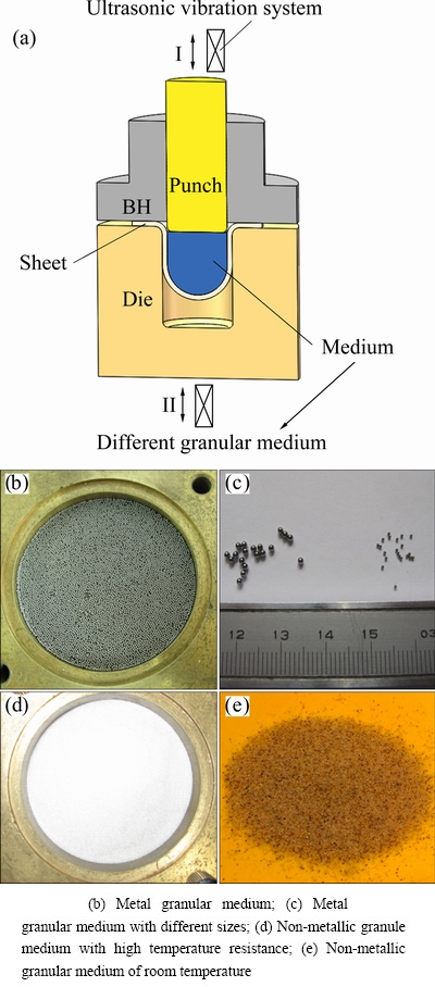
Fig. 1 Schematic of UGMF technology (a) and different granular medium
Using the finite element method, ASHIDA and AOYAMA [6] studied the influence of ultrasonic vibration on the friction state of the die, die fillet, punch, and BH during deep drawing with a rigid mold, and the results showed that the effect of friction reduction was the best when vibration and lubrication were applied to the shoulder ring of the die. In addition, vibrating the die can result in a large relative motion between the die and workpiece. Thus, ultrasonic vibrations were imposed on the die in this study, and the vibratory motion was assumed to be not transmitted to the punch.
The granule medium slides at a constant velocity v0 and is compressed by the punch. The die has an oscillatory motion of amplitude a and angular frequency �� along the same line of v0 and its oscillations velocity vD=-a��sin ��t, as shown in Fig. 2. vD is larger than the velocity of the sheet to be deformed. Given the relative velocity between the die and sheet, the micro gaps between them are created and closed at every cycle of vibration. This action changes the contact pressure characteristics at the interface. Under ultrasonic vibrations, the direction of the friction force reverses for every period of vibration, thereby changing the friction characteristics at the die�Cworkpiece interface. Thus, a properly designed UGMF system can enhance the tribological performance.
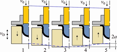
Fig. 2 UGMF technology with die vibration
This study focused on identifying the ultrasonic vibrations effects on sheet metal formability. Ultrasonic vibrations can change the friction characteristics of the die/workpiece, pressure-transmitting characteristics of the medium, and other process variables. These changes can be exploited to design the UGMF system.
3 UGMF experimental setup and test procedures
Magnesium alloy has poor formability at room temperature because of its hexagonal and closely packed crystal structure. Nevertheless, the formability of sheets can be significantly improved by increasing the temperature; hence, the deep drawing of magnesium alloy sheet is generally performed under warm/hot condition [17,19-21].
To analyze the effect and mechanism of ultrasonic vibration during the deep drawing process, AZ31B magnesium alloy sheet was selected, and a set of tooling by superimposing ultrasonic vibrations on the solid granule medium drawing technology was designed. The tooling was designed to meet the following requirements: 1) The design should be able to form the cylindrical workpiece of AZ31B magnesium alloy sheet under heating condition; 2) The design can attain the maximum relative velocity at the die/workpiece interface, and the die can bear the resultant force of the forming load and blank-holder force (BHF); 3) The setup should be designed for an ultrasonic transducer, which operates at a natural frequency f of 20 kHz with four different amplitudes; 4) The setup should be designed with the maximum output of a 1.5 kW ultrasonic generator at frequencies between 19.5 and 20.5 kHz, such that the die can be continually excited at different temperatures and loads; 5) The setup should produce longitudinal mode shapes at a natural frequency of 20 kHz to reduce the energy loss caused by the mechanical coupling of the ultrasonic excitation system and die.
To fulfill the aforementioned design requirements, a preliminary design (Fig. 3) was conceived. The main parts of the UGMF system are: 1) the ultrasonic generator, which is connected to the ultrasonic transducer, 2) the horn, which transmits the vibrations from the transducer to the die, 3) the ultrasonic vibration system is installed in a bracket, 4) the heating device, which consists of eight uniformly distributed heating rods in the BH, 5) the guide rods, which can effectively improve the positional accuracy and moving stability of the components, and 6) the BHF provided by the spring. Two rubber cushions are installed at both sides of the die flange to avoid frictional heating caused by rapid vibration.
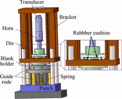
Fig. 3 Preliminary design of UGMF system
The ultrasonic vibration system includes an ultrasonic generator, transducer, and horn. The horn is used to boost high-frequency vibration and excite the die; hence, the vibration at the horn tip has a critical role in the UGMF process. The horn made of 40Cr is excited by the piezoelectric transducer in a longitudinal direction (Fig. 4). Given the high amplification ratio, a two-step horn design is employed to minimize the stress.
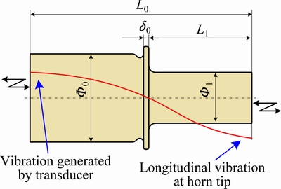
Fig. 4 Schematic of horn and vibration
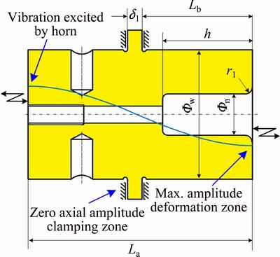
Fig. 5 Schematic of die and vibration
The die made of C12MoV is excited by the horn in the axial direction (Fig. 5). Given that the vibration amplitude is boosted by the horn, the die is to transmit a longitudinal wave at the base of the horn and attains the desired amplitude in the deformation zone. The amplification ratio of the die is 1, and the shape is a cylinder with a flange in the middle position. The figure also shows that an axial wave transmitted into the flange attains zero amplitude at the clamping zone, which is the nodal position.
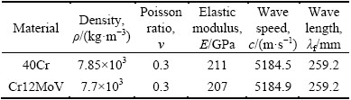
The material parameters of the horn and die used for the design are shown in Table 1. A wavelength of 259.2 mm is exhibited at the desired frequency of 20 kHz. To attain the maximum displacement amplitude in the deformation zone, the length of the horn and die should be equal to the half of the wavelength. Other main geometric parameters are iterated with the aid of the finite element method as discussed in the next section.
3.1 Finite element analysis
Finite element analysis was conducted to optimize the UGMF system. To obtain the longitudinal vibration model and reduce the energy loss caused by the mechanical coupling of the ultrasonic excitation system and die, the natural frequency of the horn and die should be close to the excitation frequency given by the transducer. To determine the remaining key dimensions of the system, modal analysis and harmonic response analysis were conducted using the finite element code ABAQUS with the material parameters listed in Table 1.
Table 1 Material and ultrasonic vibration parameters used in horn and die
Three different mode shapes of the horn were analysed within the range of 12000 to 21000 Hz, as shown in Fig. 6. A longitudinal mode shape was noted at 20045 Hz among the mode shapes in Fig. 6(b). The longitudinal mode shape of the die at 20168 Hz was obtained in the same way as shown in Fig. 7, which is required for sheet forming. The longitudinal mode shapes may enhance the tribological conditions at the die cavity�Cworkpiece interface. The longitudinal mode shape is beneficial because it reverses the friction force and forms gaps for the deep drawing processes. Figure 7 shows that the tip surface vibration displacement of the die cavity gradually decreases from the center to the edge, which indicates that the center zone of the die holds the maximum energy. The longitudinal mode shape at 20141 Hz of the assembly of the horn and die is obtained as shown in Fig. 8, which is needed for sheet forming.
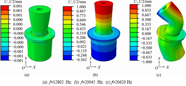
Fig. 6 Horn displacement U (longitudinal displacement U2) nephogram of model analysis
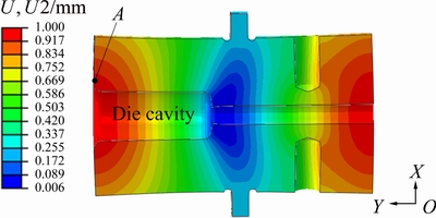
Fig. 7 Die displacement nephogram of model analysis (f=20168 Hz)
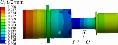
Fig. 8 Assembly displacement nephogram of model analysis (f=20141 Hz)
The next steps in the optimization of the tooling included determining the displacement amplitudes at the deformation zone because of the superimposed vibrations and checking if the stresses in the structure are within permissible limits. Ultrasonic excitation was applied on the surface of the horn where the transducer is connected. At this time, the actual displacement amplitude was unknown, and four input displacements were used in the harmonic analysis. These input displacements were 2, 3, 4, and 5 ��m. The displacements were applied as a cosine function (Eq. (1)) to mimic the ultrasonic vibrations.
ut=acos ��t (1)
The response of the die was calculated for the specified values of ��. The harmonic response analysis was conducted using the element code ABAQUS.
The frequency response of the die ranging from 18 to 21 kHz was calculated, and the response curve of point A (Fig. 7) was obtained, as shown in Fig. 9. A damping ratio of 1% was applied in the analysis. Thus, for the input displacement of 2, 3, 4, and 5 ��m, the horn exhibited longitudinal displacement amplitudes of 6, 9, 12, and 15 ��m, respectively.
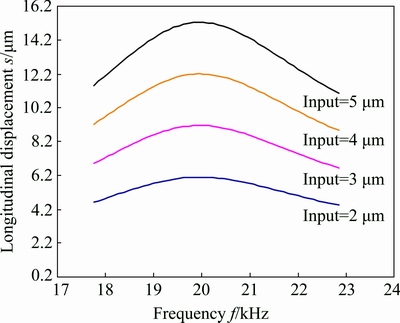
Fig. 9 Resonance plot showing displacement at surface of horn for four different displacement inputs
3.2 UGMF experimental setup
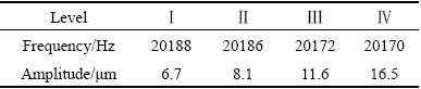
Figure 10 shows the developed UGMF experimental setup under heating condition. According to the simulation results, the optimal dimension parameters of the horn and die are listed in Table 2. The OptoMET laser scanning vibrometer was adopted to measure the amplitude of the die by superimposing ultrasonic vibration. The frequency and amplitudes of the die under no-load condition at different levels are shown in Table 3. The measured values are basically consistent with the simulation values.
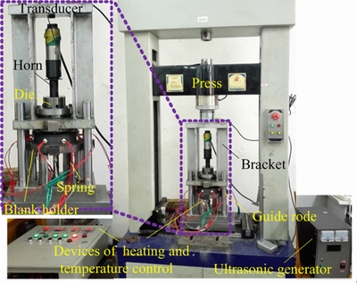
Fig. 10 Setup of UGMF system under heating condition
Table 2 Dimension parameters of horn and die (mm)
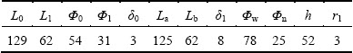
Table 3 Measured amplitudes at different levels
The WDD-LCJ-150 electronic testing machine provides the forming load to the bracket of the forming unit. The heating device consists of eight uniformly distributed heating rods in the BH and four contact thermocouples, which are used as the real-time temperature measurement system. The closed-loop temperature control system precisely controls the forming temperature and ensures that the sheet metal is heated homogeneously. In this study, the variable BHF control was used in deep drawing, and the stiffness of the spring was set according to the critical BHF [22].
The water-based MoS2 was applied evenly on both surfaces as high-temperature lubricant beforehand, and the sheet was placed between the BH and die. The selected medium consists of SiO2 granules with the diameter of 0.12-0.22 mm. When the sheet is heated to the specified temperature by the heating unit, the ultrasonic vibration system starts to work. The punch with diameter of 20 mm then compresses the solid granule medium at the speed of 60 mm/min, and the deep drawing begins.
4 Results and discussion
AZ31B sheet with a thickness of 0.8 mm is selected, and the chemical composition of the alloy is presented in Table 4. The mechanical properties are obtained by uniaxial tensile test using an InspektTable100 universal testing machine, as shown in Table 5.
Table 4 Composition of AZ31B magnesium alloy (mass fraction, %)
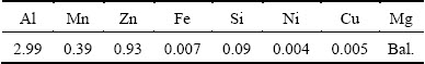
Table 5 Mechanical properties of AZ31B sheet (with a strain rate of 0.01 s�C1)

The solid granules will be agglomerated during a deep-drawing process without vibration, whereas the agglomeration can be completely broken after applying ultrasonic vibration because of the enhancement of liquidity and force transmission performance of the solid granule medium under ultrasonic vibration.
4.1 Influence of temperature on forming under ultrasonic vibration excitation
When the amplitude of ultrasonic vibration was 11.6 ��m and the initial diameter of the sheet was 55 mm, the limit drawing heights h of the workpieces at different forming temperatures T were obtained, as shown in Fig. 11.
The effect of temperature on the forming of magnesium alloy sheet is extremely obvious under ultrasonic vibration excitation (Fig. 11). Within the range of 180-300 ��C, the limit forming height h gradually increased with temperature if 180��T��260 ��C, and decreased with temperature if 260��T��300 .The deformation reduced with vibration; hence, sheet easy to produce plastic deformation. A fracture occurs when force exceeds maximum resistance force. Thus, best for alloy under 240-260 ��C, whereas static drawing is around 290��C [17]. Under vibration, remains as one main factors that influence formability of magnesium alloy. Moreover, ultrasonic vibration can efficiently lower the optimum forming temperature and energy cost.

Fig. 11 Limit drawing height h of workpieces at different temperatures
4.2 Influence of ultrasonic vibration on microstructure of workpiece
Wire electrical discharge machining was used to obtain specimens from the flange and die fillet of the workpieces. After being polished and corrosively treated, the microstructures of specimens with different vibration conditions at 260 ��C were compared using a scanning electron microscope. This aspect of the microstructure is a key factor in understanding the volume effect. The micrographs of specimens that were cut from flange and fillet are shown in Fig. 12.
Figures 12(a) and (b) show the micrographs for the flange of the samples superimposed with the amplitudes of 0 (i.e., no vibration) and 11.6 ��m, respectively. A few small twin crystals appear in the grain boundary; the grain size decreases and the evenness of the grain increases when the amplitude is 11.6 ��m, which is different from that with no vibration. The die fillet microstructures of the samples are superimposed with the amplitudes of 0 and 11.6 ��m, as shown in Figs. 12(c) and (d), respectively. Compared with those of flange, the grains of the die fillet are evidently elongated along the direction of deep drawing deformation. What��s more, the grain of sample with the amplitude of 11.6 ��m is refined and uniform compared to that of no vibration.
The above phenomenon is a result of the limited vibration energy absorbed by per unit area during the deep drawing process. The integral flange area is large and the compactness of the sheet in contact with the die in this area is determined by the BHF. While the ultrasonic energy is mostly concentrated in the die fillet (as shown in Fig. 4). The sheet warps and closely sticks to the die in this area, which effectively absorbs the vibration energy. Finally, the vibration energy speeds up the breeding and migration of the dislocation, increases the dislocation density, and produces the softening phenomenon, which reduces the drawing force, augments the elongation, and even improves the formability of the sheets.
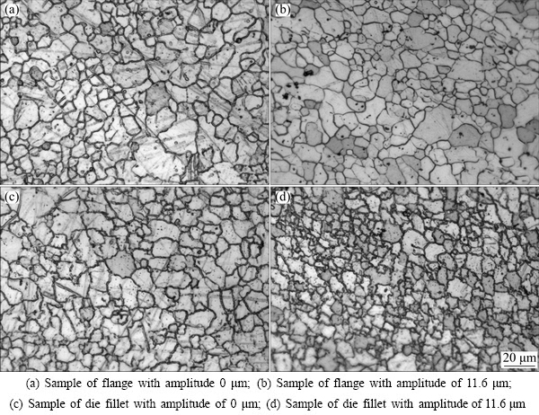
Fig. 12 Microstructures of specimens under different vibration conditions (260 ��C)
4.3 Influence of amplitude on AZ31B formability
To study the influence of the amplitudes of ultrasonic vibration on the formability of AZ31B sheet, the deep drawing experiments of cylindrical parts with the amplitudes of 0 (i.e., no vibration), 6.7, 8.1, 11.6, and 16.5 ��m, were conducted at 260 ��C. The obtained LDR values under different conditions are listed in Table 6. As the amplitudes increase, the LDR first rises then falls under the pretension force (PF) of spring, which is 612 N; 11.6 ��m is considered to be the best amplitude under these conditions. However, the forming performance of the sheet metals declines with the oversized vibration amplitudes (a=16.5 ��m) because the ��hardening�� phenomenon gradually occupies the dominant position in the volume effect, thereby inhibiting the twin crystal precipitation from the grain boundary. With vibration amplitude increasing, the LDR values decrease instead of increase when PF=748 N. The ultrasonic oscillations of the die reduce the optimum BHF, and the reduction in BHF increases with the vibration amplitudes.
Table 6 LDR values with different amplitudes (at forming temperature of 260 ��C)
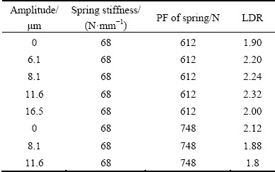
Figure 13 shows the curves of the changes in the punch load with stroke under different amplitudes. The punch load decreases with the increase of amplitude, and the load peaks with the amplitudes of 6.7, 8.1, 11.6, and 16.5 ��m are reduced by 38.7%, 37.9%, 40.6%, and 38.7%, respectively, compared to that with no vibration.
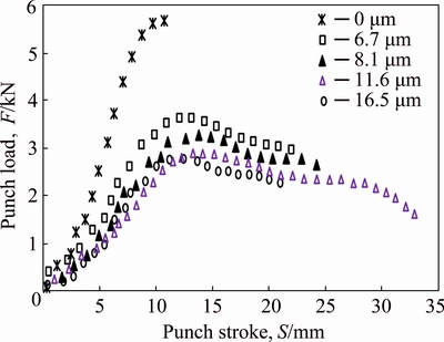
Fig. 13 Values of punch load vs stroke under different amplitudes
In the case of longitudinal vibration for the die relative to the workpiece during the deep-drawing process shown in Fig. 2, the directions of vibration and sliding are assumed to be collinear. From the theoretical predictions based on the simple Coulomb friction law of POPOV et al [9], the friction coefficient function between the sliding velocity v0 and harmonic oscillations with the velocity amplitude va of the cylinder wall in the UGMF process can be deduced as
 (2)
(2)
where va=a��, ��0 is the sliding friction coefficient, and �� is the macroscopically measured friction coefficient (i.e., averaged over the oscillation period).
As shown in Fig. 14, the ratio of friction coefficient ��/��0 increases with the increment of the ratio of sliding velocity to vibration velocity v0/va with respect to Eq. (2). ��/��0 tends to be a constant value at large sliding velocities (v0��va). When v0/va<0.5, the relationship between ��/��0 and v0/va is linear, whereas, when 0.5
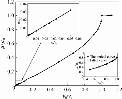
Fig. 14 Variation of ��/��0 with v0/va with respect to Eq. (2)
In summary, UGMF technology can reduce the forming load because of three possible effects. In the force superposition effect, the ultrasonic vibration changes the direction of the relative movement [23]. A change exists in the direction of the friction force, providing part of the force that assists forming. In the surface effect, by applying ultrasonic vibration, the flange of the workpiece and die present a periodic instantaneous separate state. This periodic changes the apparent friction coefficient as a result of the pumping of the lubricant phenomenon, softening or melting of the asperities, and separation of the surfaces, thereby redistributing the lubricant. Within a partial vibration period, the direction of the friction between the straight wall of the workpiece and the die is in accordance with the drawing direction, which facilitates forming and reduces the forming load. The volume effects are related to the decrease of flow stress at the fillet of the die; hence, the vibration energy speeds up the breeding and migration of the dislocation, increases the dislocation density, and produces a softening phenomenon, which in turn reduces the drawing force.
5 Conclusions
1) Ultrasonic vibration significantly influences the friction and lubrication mechanism at the die/sheet interface. Under ultrasonic vibration, the liquidity and force transmission performance of the granule medium are enhanced. The friction between the die and sheet metals can be reduced, as well as the deformation resistance. Consequently, the forming performance of the sheets is improved, the punch load is significantly reduced, and the reduction increases with the augmentation of vibration energy. Most importantly, this effect is due to the combination of volume and surface effects.
2) The optimum forming temperature and BHF of AZ31B magnesium alloy sheet decrease based on the UGMF process. Within the range of 6.7 and 11.6 ��m, the LDR value of AZ31B sheet increases gradually with increment of ultrasonic vibration amplitude, while it decreases when the amplitude increases to 16.5 ��m. By analyzing the microstructure of the deformed parts, a few small twin crystals appear in the grain boundary; the grains size decreases, and the uniformity of the grains increases in the microstructure of the flange area with an amplitude of 11.6 ��m. The grains in the die fillet are elongated obviously along the direction of the deep drawing deformation, and the degrees of grain refinement and uniformity become highly prominent compared with those without vibration.
References
[1] HUANG Y M, WU Y S, HUANG J Y. The influence of ultrasonic vibration-assisted micro-deep drawing process [J]. International Journal of Advanced Manufacturing Technology, 2014, 71(5): 1455-1461.
[2] JIMMA T, KASUGA Y, IWAKI N, MIYAZAWA O, MORI E, ITO K, HATANO H. An application of ultrasonic vibration to the deep drawing process [J]. Journal of Materials Processing Technology, 1998, 80-81: 406-412.
[3] KIM S W, LEE Y S. Investigations on the effect of ultrasonic vibration in cylindrical cup drawing processes [J]. Key Engineering Materials,2014, 622-623: 1152-1157.
[4] WEN Tong, GAO Rui, CHEN Xia. Influence of high frequency vibration on deep drawing process of AZ31 sheet at room temperature [J]. Journal of Shanghai Jiao Tong University (Science), 2012, 17(4): 456-460.
[5] SIDDIQ A, EL SAYED T. Ultrasonic-assisted manufacturing processes: Variational model and numerical simulations [J]. Ultrasonics, 2012, 52(4): 521-529.
[6] ASHIDA Y, AOYAMA H. Press forming using ultrasonic vibration [J]. Journal of Materials Processing Technology, 2007, 187-188: 118-122.
[7] DAWSON G R, WINSPER C E, SANSOME D H. Application of high and low frequency oscillations to the plastic deformation of metals [J]. Metal Forming, 1970, 8: 234-238.
[8] CAI Gai-pin, WENG Hai-shan, JIANG Zhi-hong, LUO Xiao-yan. Non-local friction surface effect and approximate solution of drawing deformation with vibration [J]. Chinese Journal of Mechanical Engineering, 2006, 42(8): 190-194. (in Chinese)
[9] POPOV V L, STARCEVIC J, FILIPPOV A E. Influence of ultrasonic in-plane oscillations on static and sliding friction and intrinsic length scale of dry friction processes [J]. Tribology Letters, 2010, 39(1): 25-30.
[10] PRESZ W, ANDERSEN B. Flexible tooling for vibration-assisted microforming [J]. Journal of Achievements in Materials and Manufacturing Engineering, 2007: 21(2): 61-64.
[11] LI Tao, LANG Li-hui, ZHOU Xian-bin. Recent developments of the advanced sheet hydroforming [J]. Journal of Plasticity Engineering, 2006, 13(3): 30-34, 47. (in Chinese)
[12] TAGHIPOUR E, ASSEMPOUR A. The effects of proportional loading, plane stress, and constant thickness assumptions on hydro-mechanical deep drawing process [J]. International Journal of Mechanical Sciences, 2011, 53: 329-337.
[13] WANG Hui-ting, GAO Lin, SHEN Xiao-hui, XU Yan. Hydraulic-pressure augmented deep drawing with fluid assisted blank holder [J]. Chinese Journal of Mechanical Engineering, 2010, 46(12): 76-80.
[14] WANG Gang, WANG Jian-long, ZHANG Tuo-da, ZHANG Zhi-peng. Quick gas blow forming behavior of AZ31B magnesium alloy sheet [J]. The Chinese Journal of Nonferrous Metals, 2011, 21(9): 2023-2027. (in Chinese)
[15] WANG Z J, LIU Y. Investigation on deformation behavior of sheet metals in viscous pressure bulging based on ESPI [J]. Journal of Materials Processing Technology, 2010, 210: 1536-1544.
[16] DONG Guo-jiang, ZHAO Chang-cai, PENG Ya-xin, LI Ying. Hot granules medium pressure forming process of AA7075 conical parts [J]. Chinese Journal of Mechanical engineering, 2015, 28(3): 580-591.
[17] CAO Miao-yan, ZHAO Chang-cai, DONG Guo-jiang. Numerical simulation on granules medium drawing parameters of magnesium alloy sheet [J]. The Chinese Journal of Nonferrous Metals, 2012, 22(11): 2992-2999. (in Chinese)
[18] DONG Guo-jiang, ZHAO Chang-cai, CAO Miao-yan. Process of back pressure deep drawing with solid granule medium on sheet metal [J]. Journal of Central South University, 2014, 21(7): 2617-2626.
[19] KOH Y, KIM D, SEOK D Y, BAK J, KIM S W, LEE Y S, CHUNG K. Characterization of mechanical property of magnesium AZ31 alloy sheets for warm temperature forming [J]. International Journal of Mechanical Sciences, 2015, 93: 204-217.
[20] LEE Y, KIM J J, KWON Y N, YOON E Y. Formability and grain size of AZ31 sheet in gas blow forming process [J]. Procedia Engineering, 2014, 81: 748-753.
[21] GALL S, COELHO R S,  S, REIMERS W. Mechanical properties and forming behavior of extruded AZ31 and ME21 magnesium alloy sheets [J]. Materials Science and Engineering A, 2013, 579: 180-187.
[22] QIN Si-ji, XIONG Bai-qing, LU Hong, ZHANG Ting-ting. Critical blank-holder force in axisymmetric deep drawing [J]. Transactions of Nonferrous Metals Society of China, 2012, 22: s239-s246. (in Chinese)
[23] BUNGET C, NGAILE G. Influence of ultrasonic vibration on micro-extrusion [J]. Ultrasonics, 2011, 51(5): 606-616.
������1�����1,2��Է����1,2���Գ���1,2
1. ��ɽ��ѧ �����������װ�������չ��̼����о����ģ��ػʵ� 066004��
2. �Ƚ���ѹ���μ������ѧ�������ص�ʵ����(��ɽ��ѧ)���ػʵ� 066004
ժ Ҫ���ۺϹ���������ʳ��κͳ��������Գ��μ�����������������������ʳ��ι��ա�Ϊ�˽�ʾ�������������ģ�����Ӱ�죬��AZ31Bþ�Ͻ��Ĺ������������������У�������Ƶ��20 kHz������������1.5 kW�ij�����ϵͳ��ģʩ�Ӽ������о����������������ٽ��������ʵ������Լ��䴫����ѹ���ܣ������ı��������еij��ι��ɲ���Ч���ͳ����غɣ������ų�����������ӣ��غɽ��ͱ���Խ�ߣ����DZ���ЧӦ�����ЧӦ�ۺ����õĽ����
�ؼ��ʣ�������þ�Ͻ�壻�����������
(Edited by Yun-bin HE)
Foundation item: Projects (51305385, 51305386) supported by the National Natural Science Foundation of China; Project (QN20131080) supported by the Science Research Youth Foundation of Hebei Province Universities, China
Corresponding author: Chang-cai ZHAO; E-mail: zhao1964@ysu.edu.cn
DOI: 10.1016/S1003-6326(17)60019-0

