Trans. Nonferrous Met. Soc. China 22(2012) s268-s274
Drawability of thin magnetron sputtered Al-Zr foils in micro deep drawing
Gerrit BEHRENS1, Julien KOVAC2, Bernd  2, Frank VOLLERTSEN1, Heinz-Rolf STOCK2
1. BIAS-Bremer Institut  Angewandte Strahltechnik GmbH, Klagenfurter Str. 2, D-28359 Bremen, Germany;
2. IWT-Stiftung Institut f��r Werkstofftechnik, Badgasteiner Str. 3, D-28359 Bremen, Germany
Received 28 August 2012; accepted 25 October 2012
Abstract: Deep drawing provides a great application potential for the manufacturing of parts with complex shapes, even when it is scaled to the micro range. Two different foils out of the Al-Zr alloy with a thickness of about 15 ��m were manufactured using a magnetron-sputtering process by applying substrate temperatures of 310 K and 433 K, respectively. These foils were used as blank material in micro deep drawing with a punch diameter of 0.75 mm to investigate the formability. Even though the materials show small ultimate strains in tensile tests, deep drawing was carried out successfully. Limit drawing ratios of 1.8 and at least 1.7 were reached for the material produced with a substrate temperature of 310 K and 433 K, respectively. These are even better results than those realized with Al-Sc alloys in former investigations. Comparison with deep drawing results of pure aluminum produced by conventional rolling shows the same achievable limit drawing ratio. This illustrates the good suitability of magnetron sputtering as a foil manufacturing process for micro sheet forming operations.
Key words: Al-Zr foil; micro deep drawing; forming limit; magnetron sputtering
1 Introduction
Deep drawing is a well-established process for three dimensional sheet metal parts fabrication. Due to the ongoing trend of miniaturization, there is a growing demand on micro formed parts [1]. These can be components of micro system technologies or micro electro-mechanical systems [2]. Deep drawing provides great application potential in manufacturing of these complex micro parts, but the smaller the dimension of the part, the more difficult the manufacturing [3]. Thus, improvement and investigation of the micro deep drawing process is needed [4]. Downscaling of the process is directly linked to the necessity of scaling the blank thickness according to the rule of similarity, too [5]. Usually, rolling is the common process to generate thin sheets. Since the investigated foil material is a high strength aluminium alloy of 15 ��m maximum thickness only, this technique is not applicable. Physical vapour deposition (PVD) is a possible attractive alternative in this case. Unlike classical alloys produced by melting metallurgy, this manufacturing method allows for production of alloys with different chemical compositions and highly enhanced content of alloying elements. In former investigations the manufacturing of high strength aluminium-scandium (Al-Sc) alloys using magnetron sputtering was successfully presented [6]. The added alloying element scandium acted as a grain refiner and recrystallization inhibitor. In this investigation, a substitution of scandium by the cheaper alloying element zirconium is intended while simultaneously keeping the good mechanical properties.
The fabricated foils were used in micro deep drawing to determine the limit drawing ratio. This ratio is defined as the maximum blank diameter that can be successfully drawn into a cup without residual flange to the punch diameter. Higher values of the limit drawing ratio indicate improved formability of the material and a better applicability in industry. Therefore, the achieved deep drawing results of this study are also compared to former deep drawing results using PVD-Al-Sc foils to evaluate the suitability for industrial application of Al-Zr alloys.
2 Experimental
2.1 Fabrication of Al-Zr foils by physical vapour deposition
Al-Zr films were deposited in a magnetron sputtering unit with DC power supply. A rectangular target (dimensions: 488 mm �� 88 mm �� 10 mm) of aluminum containing 4% (mass fraction) zirconium was employed and unalloyed steel sheets of 100 ��m thickness were used as substrate. During the deposition process, the target power was kept constant at 1 kW and argon was used as sputtering gas (pressure: 0.7 Pa). In order to reach a thickness of 15 ��m the process ran for 105 min. The substrate holder was located at a distance of 50 mm from the target and allowed a temperature regulation in the range of 310-573 K. In this way two Al-Zr films were produced with substrate temperatures of 310 and 433 K (37 and 160 ��C). After deposition, the coated substrates were immersed in a 65% nitric acid solution to dissolve the steel substrate resulting in freestanding Al-Zr films. Glow discharge microscopy measurements revealed a zirconium content of 3.18% and 3.02% (mass fraction) in the foils produced at 310 K and 433 K, respectively. Scanning electron microscopy was used to examine the sheets and mechanical properties were investigated using tensile tests.
2.2 Micro deep drawing
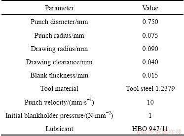
The fabricated Al-Zr films were cut by a Nd:YAG laser with a wave length of 1064 nm to produce the necessary circular blanks for micro deep drawing. The geometrical parameters as well as the process conditions of the deep drawing experiments are shown in Table 1. In order to study the drawability of the foil material different blank diameters were used. They were varied in steps from 1.125 mm to 1.425 mm to investigate the drawing ratios of 1.5 to 1.9. To verify the achieved diameters from laser-cutting and for surface roughness measurement, a Keyence VK9700 confocal microscope was used. The deep drawing experiments were carried out on a single-axis micro forming press with 500 N maximum punch force and 30 mm/s maximum punch velocity driven by a servomotor controlled by a MADIS4000 positioning system. The press is equipped with an aerostatic bearing to reduce frictional loss and to guarantee precise adjustment of the blankholder force. For force measurement a system with 0.01 N accuracy was used. The detection of the punch stroke was realized using a resistive travel sensor with a repeat accuracy of 0.002 mm. In order to ensure uniform deep drawing conditions the smooth side of the foil was positioned on the die for all experiments. For every experimental variant at least six specimens were tested and the punch force versus stroke curves were detected.
Table 1 Specifications of deep drawing setup
3 Results
3.1 Properties of Al-Zr foils
Figure 1 features SEM pictures presenting the typical aspect of Al-Zr sheets. It can be seen that the sheets present two different surfaces. The free surface of the sheets has a relatively rough relief due to the tapered shape of the top of columnar crystallites growing during the deposition process. In comparison, the surface that was in contact with the substrate presents a smoother relief characterized by long streaks which is mirroring the surface of the cold rolled steel sheet used as substrate.
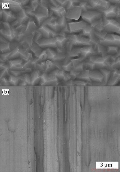
Fig. 1 SEM micrographs of free surface (a) and contact surface (b) of Al-Zr film
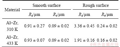
Surface roughness measurements of the foil material revealed a very similar surface roughness for the smooth foil surfaces, independent of the material (see Fig. 2 and Table 2). In contrast, there are significant differences in surface roughness compared with the rough surfaces of both materials. The average roughness Rz of the 310 K material is larger by the factor of 1.75 than the 433 K material.
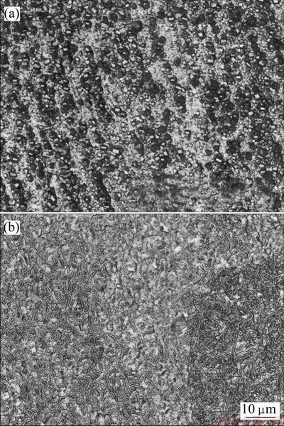
Fig. 2 Confocal microscope pictures of rough foil surface of 310 K material (a) and 433 K material (b)
Table 2 Surface roughness measurement with indication of standard deviation for both materials and foil surfaces
To reveal the grain structure of the cross section of the sheets, optical microscopy observations were carried out and compared to an Al-Sc sheet produced under similar conditions (1 kW, 310 K). As shown in Fig. 3, the structure of sputtered Al-Zr sheets consists of fine grains oriented in the direction of film growth (i.e., perpendicular to the sheet��s plane). In comparison to the Al-Sc sheet, the Al-Zr foils seem to have a finer grain structure.
The mechanical properties of the Al-Zr foils produced were investigated with tensile tests. Figure 4 exhibits exemplary stress��strain curves of Al-Zr sheets produced with substrate temperatures of 310 K and 433 K as well as exemplary stress��strain curves of two Al-Sc sheets investigated in Ref. [6] and produced under similar conditions.
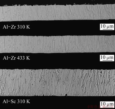
Fig. 3 Optical micrographs of cross sections of two Al-Zr sheets produced at 310 K and 433 K respectively and of Al-Sc sheet produced with substrate temperature of 310 K
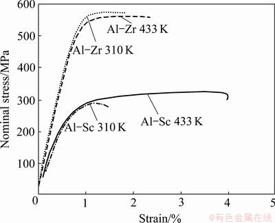
Fig. 4 Exemplary stress��strain curves of magnetron sputtered Al-Zr sheets and Al-Sc sheets produced with target power of 1 kW and substrate temperatures of 310 and 433 K
Al-Zr sheets have significantly higher tensile strength than Al-Sc sheets. However, Al-Zr sheets tend to show smaller elongations to fracture. The tensile strength of Al-Zr sheets was evaluated to (578��9) MPa for a substrate temperature of 310 K and to (572��22) MPa for a substrate temperature of 433 K, whereas the Al-Sc sheets exhibit tensile strengths of (292��7) MPa and (332��8) MPa at 310 and 433 K, respectively. In addition, it is noticeable that an increase of the substrate temperature increases the tensile strength of Al-Sc foils slightly, whereas the Al-Zr foils show comparable tensile strengths.
3.2 Determination of limit drawing ratio
The micro deep drawing tests revealed a limit drawing ratio of ��=1.8 for material fabricated with a substrate temperature of 310 K. For Al-Zr sheets sputtered at an elevated substrate temperature of 433 K, the biggest drawing ratio providing reproducible sound parts was found to be ��=1.7. A drawing ratio of ��=1.8 always led to wrinkling of the cup walls using this material variant (see Fig. 5(f)). For all drawing ratios smaller than these, starting with ��=1.5, sound parts could be achieved using both materials in all experiments. Figure 5 gives an overview of the most important experimental variants and the resulting cup geometries. For the material produced at 310 K, exceeding of the limit drawing ratio of ��=1.8 results in defective drawn parts with wrinkling of the cup walls and bottom fractures (see Fig. 6). For comparison purposes, the cup geometries and achieved limit drawing ratios using Al-Sc PVD foils from former investigation [6] are shown in Fig. 7. The limit drawing ratio of both investigated materials was limited to ��=1.6.
3.3 Determination of maximum punch force
In Fig. 8 punch forces versus stroke curves of the most important experimental variants are shown exemplarily.
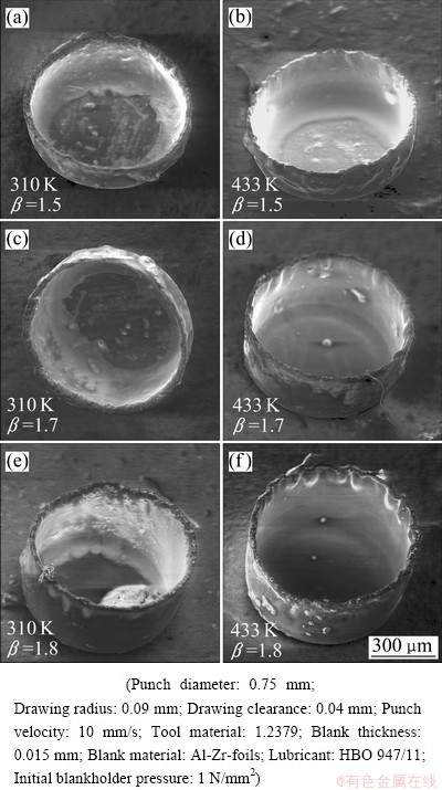
Fig. 5 Sound parts produced by micro deep drawing of two different Al-Zr foils with different drawing ratios ((a)�C(e)) and failure part with wrinkling (f)
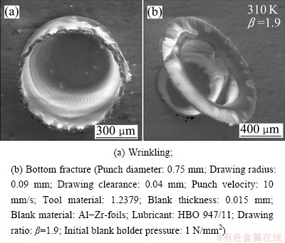
Fig. 6 Failure parts caused by exceeding of limit drawing ratio. Both from the same experimental variant
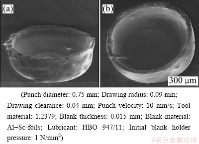
Fig. 7 Sound parts from Al-Sc foils with limit drawing ratio of ��=1.6 [6]
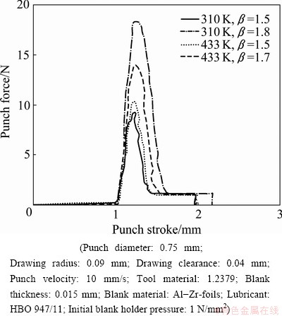
Fig. 8 Exemplary punch force versus stroke curves from micro deep drawing of Al-Zr foils
The curve shows an increase and decrease in force typical during the forming process. After a specific punch stroke, which increases with increasing drawing ratio, the forming is finished and the force is stabilizing at a constant force of about 1 N until the whole punch stroke is finished and the punch is removed from the specimen. This plateau marks that stage of the process where the cup is already drawn into the die completely but is still moved down inside the die hole which results in a constant friction and therefore a constant force for the rest of the punch movement.
Since the most significant parameter describing the deep drawing process is the maximum punch force, it is sufficient to focus on this parameter and its scattering. Figure 9 gives a summary of the average maximum punch forces for all experimental variants and the associated standard deviations.
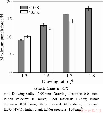
Fig. 9 Average maximum punch forces and standard deviations for all relevant experimental variants
For both foil materials the maximum punch force increases with increasing drawing ratio, but this effect seems to be more pronounced for material produced at substrate temperature 310 K. Although the material with substrate temperature 433 K starts at higher forces compared to the material sputtered at lower temperature, the maximum forces constantly fall below the values of the 310 K material at higher drawing ratios. The standard deviation of all experiments varies between 1% and 4%.
4 Discussion
4.1 Properties of Al-Zr foils
The fine columnar structure shown in Al-Zr foils is a standard feature of films produced by physical vapor deposition processes. The historical model describing the structure of thin films produced by sputtering is called structure zone model and takes in account two parameters: the ratio of the substrate temperature to the melting point (T/Tm) of the material and the pressure [7]. This model classifies the morphology in different zones according to the ratio of T/Tm and the pressure. In Al-Zr films the melting point of aluminum matrix is 660.8 ��C (933.8 K) according to MURRAY et al [8], whereas complete fusion occurs only at temperatures above approximately 1150 ��C (1423 K). This is the case for systems at thermodynamic equilibrium. However, films produced by magnetron sputtering generally consist of an out-of-equilibrium extended solid solution when substrate temperature is low. The maximum solubility of zirconium in aluminum at thermodynamic equilibrium is 0.28% (mass fraction) [8]. The sputtered Al-Zr alloys contain 3.18% Zr for 310 K substrate temperature and 3.02% Zr for 433 K substrate temperature respectively. The excess should turn into an Al3Zr phase. Nevertheless this requires temperature close to 400 ��C (673 K) and considerable time [9], which is not the case in the experiment. Consequently, no or few precipitations occur and the Al-Zr films consist of an aluminum solution containing about 3.1% Zr. Working under this assumption the melting point of the film can be evaluated to 933.8 K, i.e. the melting point of the solid solution. Under these conditions, the ratio T/Tm of the films produced at 310 K and 433 K are 0.33 and 0.46, respectively. With a pressure of 0.7 Pa, the structure zone model indicates morphology in the transition zone consisting of a dense array of fibrous grains separated by real grain boundaries, which is consistent with the observations made (Figs. 1 and 3).
The size of the surface crystallites in Al-Zr foils measured on the free surface of the sample is approximately 2 ��m (Fig. 1) which is smaller than 4 ��m measured in Al-Sc films [6]. This shows that the Al-Zr films have a finer grain structure, which is in accordance with optical microscopy observations. Since the melting point of the aluminum solution in Al-Sc alloys is also 933.8 K [10], the structure zone model described earlier, fails to explain this difference. On the other hand, the deposition time required to reach a thickness of 15 ��m (105 min) is shorter than that of Al-Sc films [6], the deposition rate is thus higher in Al-Zr films. As described by PAULEAU [11], increasing the deposition rate reduces surface diffusion and consequently films with finer structure are produced. This finer grain structure can explain the higher tensile strength of Al-Zr films. Actually, as reported from RITTNER et al [12], reducing the grain size of Al-Zr alloys results in a considerable increase of the tensile strength, but also contributes to favour brittle failure of the sample which can reduce ductility.
In Al-Sc films, increasing the substrate temperature can slightly raise the tensile strength (Fig. 4). For a temperature of 433 K, Al-Sc alloys were not reported to show considerable precipitation hardening [13], which is consistent with the fact that only a small increase in tensile strength was observed. On the other hand, in Al-Zr, precipitation was reported to be considerably slower due to the poor diffusion of zirconium into aluminum [14], which could be why no increase of tensile strength was observed in the Al-Zr film produced with a substrate temperature of 433 K.
4.2 Limit drawing ratio in micro deep drawing
As described earlier, the blankholder pressure was kept constant for all experiments. As shown in Fig. 6, the material with 310 K substrate temperature revealed both wrinkling and bottom fractures at the drawing ratio of ��=1.9 and no sound parts could be achieved. This is a clear indicator for the limit drawing ratio of ��=1.8 for the material with 310 K substrate temperature, even though the blankholder pressure was not varied.
For the material with a substrate temperature of 433 K, the exact limit drawing ratio could not be determined without varying the blankholder pressure. As presented the maximum value of the drawing ratio to produce sound parts was 1.7. A ratio of ��=1.8 resulted in wrinkling but no bottom fractures were found. Therefore, the actual limit drawing ratio has to be ��=1.7 or even higher. For its reliable determination, further investigations with increased blankholder pressures will be necessary.
The comparison of the achieved drawability of the Al-Zr material of this study with the results of former investigations using the Al-Sc foil material shows significantly increased limit drawing ratios for both Al-Zr foils. As presented in Fig. 7, the limit drawing ratio of both investigated Al-Sc materials was limited to ��=1.6 while the Al-Zr shows a limit drawing ratio of 1.8 for the 310 K material and can be expected to be 1.7 or higher for the 433 K material. This was not expected since the deep drawing conditions were comparable and Al-Sc alloys promise slightly advantageous mechanical properties. One possible explanation for better drawability of the Al-Zr material might be its finer grain structure. As shown in Ref. [15], a number of grains involved in a micro forming process affect the forming limit of very thin foils essentially. The more the grains involved in the forming are, the higher the forming limit can be expected. However, within the framework of this investigation, only a qualitative statement concerning the grain size can be made. In order to be able to make precise conclusions, further investigations on this effect have to be made using e.g. electron backscatter diffraction as examination method.
Comparing the functional drawing ratios of Al-Zr material with micro deep drawing investigations on pure aluminium, it shows the same achievable limit drawing ratio of ��=1.8 [16]. In our experiment the deep drawing setup was even 25% smaller and therefore more sensitive but the same limit drawing ratio could be achieved. This illustrates the very good drawability of the investigated Al-Zr material and additionally proves that the alternative sheet manufacturing method of magnetron sputtering offers just as good foil material as a rolling process to ensure a stable micro deep drawing process.
4.3 Maximum punch force in micro deep drawing
In micro deep drawing, a frequently observed phenomenon is an increase of scattering of the punch force compared to macro deep drawing [17]. With respect to the detected standard deviation, this also applies for the maximum punch forces in this investigation. At the moment there is no generally valid explanation for the increased scatter of punch force with decreased size. But in this particular case one explanation is the inhomogeneity of the foil thickness. Due to the specific characteristic of the magnetron sputtering process, the thickness of the deposited material is much more inhomogeneous than in a rolling process. Fluctuations of ��1 ��m in thickness are not uncommon. For a desired foil thickness of 15 ��m this means a change of ��7% and might be therefore a very likely influencing factor on the punch force and suited to explain the observed standard deviations up to 4%.
5 Conclusions
1) Magnetron sputtering can be applied to fabricate Al-Zr alloys at substrate temperatures of 310 K and 433 K.
2) These foil materials with a thickness of 15 ��m were successfully applied to micro deep drawing using a punch diameter of 0.75 mm.
3) Limit drawing ratios of ��=1.8 for Al-Zr at a substrate temperature of 310 K and at least ��=1.7 for 433 K substrate temperature were acquired experimentally.
4) Both Al-Zr materials show a better application potential in micro deep drawing than PVD-Al-Sc alloys sputtered under the same conditions.
5) Deep drawing of the investigated PVD-Al-Zr material exhibits the same limit drawing ratio as micro deep drawing of pure aluminum manufactured by rolling.
Acknowledgements
The authors gratefully acknowledge the financial support by the German Research Foundation (DFG) for the subprojects A1, B4 and B7 of the Collaborative Research Centre 747.
References
[1] HIRT G, BAMBACH M, JUSTINGER H, ZHAO K. Importance of size effects in micro sheet metal forming [C]// VOLLERTSEN F. Size Effects in Manufacturing Processes. BIAS Verlag Bremen, 2009: 117-134.
[2] SCHULZE NIEHOFF H. Development of an highly dynamic double action micro forming press [M]. Strahltechnik 33, BIAS Verlag Bremen, 2008.
[3] VOLLERTSEN F, HU Z, SCHULZE NIEHOFF H, THEILER C. State of the art in micro forming and investigations into micro deep drawing [J]. Journal of Materials Processing Technology, 2004, 151: 70-79.
[4] GEIGER M, KLEINER M, ECKSTEIN R, TIESLER N, ENGEL U. Microforming [J]. Annals of CIRP 50, 2001: 445-462.
[5] PAWELSKI O. Ways and limits of the theory of similarity in application to problems of physics and metal forming [J]. Journal of Materials Processing Technology, 1992, 34: 19-30.
[6] VOLLERTSEN F, HU Z, STOCK H R, KOEHLER B. On the limit drawing ratio of magnetron sputtered aluminum-scandium foils within micro deep drawing [J]. Production Engineering��Research and Development, 2010, 4(5): 451-456.
[7] THORNTON J A. Influence of apparatus geometry and deposition conditions on the structure and topography of thick sputtered coatings [J]. Journal of Vacuum Science and Technology, 1974, 11(4): 666-670.
[8] MURRAY J, PERUZZI A, ABRIATA J P. The Al-Zr (aluminum-zirconium) system [J]. Journal of Phase Equilibria, 1992, 13(3): 277-291.
[9] KNIPLING K E, DUNAND D C, SEIDMAN D N. Precipitation evolution in Al-Zr and Al-Zr-Ti alloys during isothermal aging at 375-425 ��C [J]. Acta Materialia, 2008, 56(1): 114-127.
[10] CACCIAMANI G, RIANI P, BORZONE G, PARODI N, SACCONE A, FERRO R, PISCH A, SCHMID-FETZER R. Thermodynamic measurements and assessment of the Al-Sc system [J]. Intermetallics, 1999, 7(1): 101-108.
[11] PAULEAU Y. Handbook of thin films [M]. Vol. 1. NALWA H S, eds. Los Angeles: Elsevier Inc., 1992: 455.
[12] RITTNER M N, WEERTMAN J R, EASTMAN J A, YODER K B, STONE D S. Mechanical behavior of nanocrystalline aluminum- zirconium [J]. Material Science and Engineering A, 1997, 237(2): 185-190.
[13] DAVYDOV V G, ROSTOVA T D, ZAKHAROV V V, FILATOV Y A, YELAGIN V I. Scientific principles of making an alloying addition of scandium to aluminum alloys [J]. Materials Science and Engineering A, 2000, 280(1): 30-36.
[14] KNIPLING K E, KARNESKY R A, LEE C P, DUNAND D C, SEIDMAN D N. Precipitation evolution in Al-0.1Sc, Al-0.1Zr and Al-0.1Sc-0.1Zr (at. %) alloys during isochronal aging [J]. Acta Materialia, 2008, 58(15): 5184-5195.
[15] HU Z, WIELAGE H, VOLLERTSEN F. Forming behavior of thin foils [C]// DUFLOU J R, CLARKE R, MERKLEIN M, MICARI F, SHIRVANI B, KELLENS K. 14th International Conference on Sheet Metal (SheMet11). Zurich-Durnten: TransTech Publication, 2011: 1008-1015
[16] HU Z, VOLLERTSEN F. Effect of size and velocity dependent friction in deep drawing on the process window [C]// FELDER E, MONTMITONNET P. 4th International Conference on Tribology in Manufacturing Processes (ICTMP2010). Paris: Transvalor, 2010: 583-592.
[17] VOLLERTSEN F, HU Z. On the drawing limit in micro deep drawing [J]. Journal for Technology of Plasticity, 2007, 32(1-2): 1-11.
�ſؽ���Al-Zr��Ĥ����������е���������
Gerrit BEHRENS1, Julien KOVAC2, Bernd 2, Frank VOLLERTSEN1, Heinz-Rolf STOCK2,
1. BIAS-Bremer Institut Angewandte Strahltechnik GmbH, Klagenfurter Str. 2, D-28359 Bremen, Germany;
2. IWT-Stiftung Institut f��r Werkstofftechnik, Badgasteiner Str. 3, D-28359 Bremen, Germany
ժ Ҫ��������ο��������Ʊ���״���ӵ��㲿���������ɴ��ӹ�ˮƽ�����ôſؽ��䷽�����ڻ����¶ȷֱ�Ϊ310 K��433 K�£��Ʊ��˺��ԼΪ15 ��m�����ֲ�ͬ��Al-Zr��Ĥ���������ֱ�Ĥ��Ϊ���ϣ����ó�ͷֱ��Ϊ0.75 mm�������豸�о����������ܡ���Ȼ�����ֲ�����������������ʾ����С�����Ӧ�䣬�����dzɹ���ʵ����������Ρ��ڻ����¶�Ϊ310 K��433 K�Ʊ������ֲ��ϵļ�������ȷֱ�Ϊ1.8��1.7����Щ�������ǰ����Al-Sc�Ͻ�Ľ��Ҫ�ã�����ô�ͳ���Ʒ������ô�����Ĥ�����������ơ�������������ôſؽ��䷽���Ʊ��ı�Ĥ������������������Ρ�
�ؼ��ʣ�Al-Zr��Ĥ��������Σ����μ��ޣ��ſؽ���
(Edited by YUAN Sai-qian)
Corresponding author: Gerrit BEHRENS; E-mail: behrens@bias.de; kovac@iwt-bremen.de
DOI: 10.1016/S1003-6326(12)61718-X

