
Microstructural zones and tensile characteristics of friction stir welded joint of TC4 titanium alloy
LIU Hui-jie (刘会杰), ZHOU Li (周 利)
State Key Laboratory of Advanced Welding Production Technology,Harbin Institute of Technology, Harbin150001, China
Abstract: TC4 titanium alloy was friction stir welded using a W-Re pin tool, and the defect-free weld was produced with proper welding parameters. The joint consists of stir zone, heat affected zone and base material. The stir zone is characterized by equiaxed dynamically recrystallized α phases and transformed β phases with fine α+β lamellar microstructure. The microstructure of the heat-affected zone is similar to that of the base material, but there is an increase in the volume fraction of β. Transverse tensile strength of the joint is 92% that of the base material, and the joint is fractured in the stir zone and the fracture surface possesses typical plastic fracture characteristics. The stir zone is the weakest part of the joint, through which the tensile characteristics of the TC4 joint can be explained.
Key words: friction stir welding; titanium alloy; microstructural zones; tensile characteristics
1 Introduction
Since the introduction of titanium and titanium alloys in the early 1950s, TC4 titanium alloy has in a relatively short time become backbone material for the aerospace, energy, and chemical industries due to its excellent comprehensive properties[1]. With the increase in the use of TC4 titanium alloy, the demand for high performance joints has become more and more stringent. Almost all conventional welding technologies have been applied to join TC4 titanium alloy. However, the application of fusion welding techniques to TC4 titanium resulted in the formation of brittle coarse microstructure, severe deformation and large residual stress. Therefore, solid-state bonding methods are more suitable to avoid the problems associated with the melting of materials to be welded.
Friction stir welding (FSW) has been used to weld a wide variety of metals and alloys, including all types of Al alloys, some Mg alloys and Cu alloys since it was invented in 1991. More recently, some high melting point materials such as ferrous and austenitic steels have been welded successfully by FSW process, but other high melting point materials, especially Ti, Ni and their alloys, are difficult to create sound joint because of tool limitations[2-4]. Until now, there has been limited information in the archival literature regarding FSW of titanium alloys. LEE et al[5] and ZHANG et al[6] conducted FSW of commercially-pure titanium. REYNOLDS et al[7] and KNIPLING et al[8] reported shear textures in FSW welds of Timetal 21S β-titanium alloy and Ti-5111 near-α titanium alloy, respectively. RAMIREZ and JUHAS[9] and WANG et al[10] clarified the microstructural features of the stir zone (SZ) and thermo-mechanically affected zone (TMAZ) in Ti-6Al-4V FSW welds. MIRONOV et al[11-12] reported the crystallography of transformed β microstructure and development of grain structure in friction stir welded Ti-6Al-4V alloy. PILCHAK et al[13-14] studied the effect of friction stir processing (FSP) on the microstructure and properties in investment-cast Ti-6Al-4V. The characterization of superplastically formed friction stir weld in Ti-6Al-4V was reported by SANDERS et al[15-16] and EDWARDS et al[17]. LUAN et al[18] and ZHANG et al[19] performed FSW on Ti-6Al-4V plates and reported microstructure and mechanical properties of the welds.
These cited literatures have yielded some important knowledge on FSW for titanium alloy, but there are relatively few systematic studies on the relationship between the microstructure and mechanical properties.
In the present study, TC4 titanium alloy is friction stir welded using a W-Re pin tool, and the microstructural zones and tensile fracture characteristics are studied to reveal the relationship between the microstructures and mechanical properties.
2 Experimental
The base material used in the experiment was 2 mm-thick mill annealed TC4 titanium alloy sheet with the following chemical composition: Al 6.15, V 4.00, Fe 0.30, C 0.10, N 0.05, H 0.015, O 0.20 and balance Ti (mass fraction, %). Welding experiments were performed using a W-Re pin tool installed in a special welding system designed by Harbin Institute of Technology, China (Fig.1). To prevent the welding zone and pin tool from oxidizing, a shielding gas shroud backfilled with argon was installed in the welding system. The welding system also had a liquid cooled tool holder to protect the FSW machine shaft from thermal breakdown. High temperature resistant materials such as stainless steel should be chosen as anvil plate due to higher temperature encountered during the FSW. All the welds were made along the longitudinal direction of the sheet, perpendicular to the rolling direction of the sheet, at a tool rotation rate of 400 r/min and at a welding speed of 50 mm/min. During the FSW, a 2.5° tilt was applied to the pin tool.
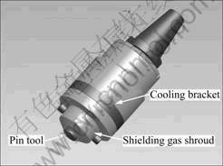
Fig.1 Special welding system for FSW of titanium alloys
The transverse weld cross-sections were cut by electrical discharge machining and prepared by standard metallographic procedure. The microstructures were observed by optical microscopy (OM) and transmission electron microscopy (TEM). The polished weld cross-sections were chemically etched using Kroll’s reagent (13 mL HF, 26 mL HNO3 and 100 mL H2O) and then observed on an Olympus-PMG3 OM. Thin-foil disk specimens were cut from the base material (BM) and the SZ for the TEM observation. TEM specimens were first mechanically polished to a thickness of 0.1 mm and then twin-jet electro-polished in a solution of 6% HClO4 + 34% C4H9OH + 60% CH3OH (volume fraction). TEM observations were carried out on a Philips CM-12 microscope operated at 120 kV.
Transverse tensile tests were carried out on an Instron-1186 mechanical tester using a crosshead speed of 0.5 mm/min at room temperature. The tensile fracture surfaces of the joint were observed by a Hitachi S-4700 scanning electron microscopy (SEM). Vickers hardness was measured along the transverse joint centerline on an HVS-1000 Vickers hardness tester using a load of 4.9 N for 20 s.
3 Results and discussion
3.1 Weld formation of joint
Fig.2(a) shows the surface appearance of the TC4 joint. It can be seen that the joint has an excellent surface appearance without any oxidization color. This indicates that the designed welding system is suitable for FSW of titanium alloys and excellent weld formation can be obtained when proper welding parameters are used.
Fig.2(b) shows a typical low magnification overview of the TC4 weld cross-section, where RS and AS stands for the retreating side and the advancing side,
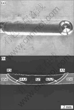
Fig.2 Weld formation of joint: (a) Weld surface appearance; (b) Weld cross-section
respectively. The central darker zone corresponds to the weld; the sideward lighter zone is the BM. A full penetration weld is obtained and the weld thickness is slightly smaller than that of the BM. The weld cross-section looks like ‘basin-shape’ and no volumetric defect is observed on the cross-section of the weld.
3.2 Microstructural zones of joint
On the TC4 weld cross-section (Fig.2(b)), the narrow gray zone between the weld and the BM is the heat-affected zone (HAZ). Compared with the microstructural zones of aluminum alloy weld, the most striking feature of the TC4 weld is the absence of apparent TMAZ, thus the weld only consists of SZ, instead of SZ + TMAZ. Similar results have ever been observed in Refs.[5, 6, 19]. It is well known that the TMAZ is between the HAZ and the SZ, and the TMAZ is characterized by largely deformed grains. The lack of TMAZ in the weld is attributed to the accommodation and distribution of the sizeable strains associated with the SZ through the surrounding material, which may be decided by the deformation compatibility of TC4 titanium alloy. As will be discussed later, the phase transformation during the FSW also has an effect on whether the TMAZ exists or not. The narrow HAZ is related with much lower thermo-conductivity of TC4 titanium alloy (17 W/(m・K)) than that of aluminum alloys (210 W/(m・K)).
3.2.1 Base metal zone
According to OM observation, the BM has an initial microstructure characterized by elongated primary α and transformed β as shown in Fig.3(a). The BM is rolled in the α+β temperature range, and annealed below the β-transus temperature followed by air cooling. The white and grey regions in the OM image represent primary α and transformed β, respectively.
TEM observations can further reveal the detailed microstructure of the BM. A large amount of dislocation substructures exist in primary α, as shown in Fig.3(b). The substructures tend to be straight and regular. This indicates that recovery occurs in the milled BM during the annealing process. Transformed β is characterized by secondary α phase and residual β phase due to the addition of β stable element V[20], as shown in Fig.3(c).
3.2.2 Stir zone
The material in the SZ reaches high temperatures and experiences high strains during FSW. The material works at temperature high enough to induce recrystallization, and several mechanisms based on dynamic recrystallization (DRX) have been proposed to explain grain refinement in the SZ of aluminum alloys[21-23]. However, the microstructural evolution in titanium alloy FSW joints is less well understood due to the involvement of complicated solid-state trans-
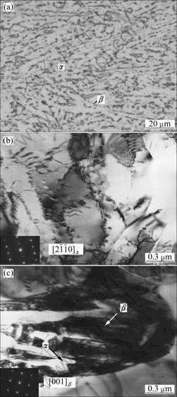
Fig.3 Microstructures of BM: (a) OM micrograph; (b) TEM image of primary α; (c) TEM image of transformed β
formation during the process, especially for α+β titanium alloys. It has been reported that the maximum temperature can exceed the β-transus temperature in the SZ, thus a fully lamellar microstructure is formed[9, 19]. However, the SZ only consists of equiaxed primary α and transformed β in the present study, as shown in Fig.4(a). Similar result has also been reported by PILCHAK et al[13]. Compared with the BM, the microstructure in the SZ is significantly refined. However, the details of transformed β cannot be revealed by OM due to the fine microstructure in the SZ.
Microstructural evolution in the SZ is further revealed by TEM. Large amounts of equiaxed primary α grains with low dislocation density are formed in the SZ, as shown in Fig.4(b). It can be confirmed that DRX has occurred in the SZ due to significant plastic deformation and frictional heating during the FSW[24]. Transformed β in the SZ is characterized by fine lamellar α+β microstructure, as shown in Fig.4(c), and thus microstructure in the SZ can be defined as bimodal microstructure[20]. The formation of bimodal microstructure in the SZ suggests that the peak temperature is below the β-transus temperature, and primary α recrystallization known as α globularization proceeds in the SZ during the heating stage of the welding process. The β→α+β transformation is produced in the cooling stage of the FSW process, resulting in fine alternate lamellar α+β microstructure due to the relatively high cooling rate; therefore, a bimodal microstructure is developed in the SZ.
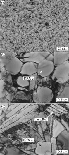
Fig.4 Microstructures of SZ: (a) OM micrograph; (b) TEM image of DRX α; (c) TEM image of transformed β
3.2.3 Heat affected zone
The material in heat affected zone experiences no detectable plastic strain during FSW. Therefore, any microstructural evolution in this region results from the temperature increases generated during FSW and any residual strains remaining from the prior material processing history. There is no substantial residual strain in the as-received mill annealed TC4 sheet, thus the microstructure of the HAZ mainly depends on the temperature history during FSW. As seen in Fig.2(b), the shape of the HAZ is irregular and the maximum width of the HAZ is less than 0.5 mm, and it is only observed by OM because of the great difficulty in TEM specimen preparation. As shown in Fig.5, the microstructure of the HAZ is similar to that of the BM, but there is an increase in the volume fraction of β.
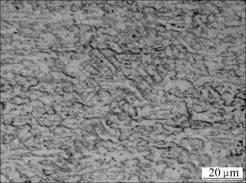
Fig.5 Optical micrograph of HAZ
The increase of β in the HAZ can be explained by the annealing effect due to the friction heat during FSW. It is indicated that temperature in the HAZ is below the β-transus temperature but above β→α+β transformation temperature, thus α→β transformation can occur in this region in the heating stage of the FSW process, resulting in an increase in the volume fraction of β. However, the high-temperature residence time in the HAZ is relatively short, so the increase in the volume fraction of β is not significant.
3.3 Tensile characteristics of joint
Fig.6(a) shows the transverse tensile test result of the TC4 joint. The average tensile strength of the joint is up to 953 MPa, which is equivalent to 92% that of the BM. This indicates that the TC4 titanium alloy can be joined successfully by FSW. All the tensile samples are fractured in the SZ during the tensile tests, as shown in Fig.6(b). All the fracture surfaces possess typical plastic fracture characteristics, i.e. fine and uniform dimples, as shown in Fig.6(c).
In order to explain the tensile characteristics of the joint, the Vickers hardness distribution of the joint was measured, as shown in Fig.7. The HAZ has a slightly lower hardness than the BM, while the lowest hardness is found in the SZ. No significant hardness difference between the RS and AS is seen because there is no significant difference in microstructure between the RS and AS. The slight decrease in hardness in the HAZ can be explained by the increase in the volume fraction of β
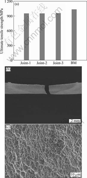
Fig.6 Transverse tensile characteristics of joint: (a) Tensile strength; (b) Fracture location; (c) Fracture surface morphology
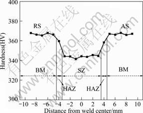
Fig.7 Vickers hardness distribution in joint
due to the annealing effect, as mentioned above. As for the SZ, it experiences DRX induced by the friction stir heating and plastic deformation imposed by the pin tool. It is well known that the deformed material is softened during recovery or recrystallization, accordingly this gives the explanation for the hardness decrease in the SZ.
Many studies have demonstrated that a friction stir welded joint having a heterogeneous hardness distribution fails in the minimum hardness region and the tensile properties of the joint are dependent on the minimum hardness region in the entire joint. Therefore, the TC4 joint is fractured in the SZ during the tensile test because there is a lowest hardness in the SZ, and the TC4 joint possesses a lower strength than the BM because the SZ possesses a lower hardness than the BM.
4 Conclusions
1) TC4 titanium alloy can be friction stir welded successfully using a specially designed welding system composed of W-Re pin tool, liquid cooled tool holder and shielding gas shroud. Excellent weld formation can be obtained under proper welding conditions.
2) The FSW joint of TC4 titanium alloy consists of SZ, HAZ and BM. The SZ is characterized by equiaxed dynamically recrystallized α grains and transformed β with fine α+β lamellar microstructure. The microstructure of the HAZ is similar to that of the BM, but there is an increase in the volume fraction of β. The microstructural evolution of these regions can be reasonably explained by taking into account of the solid-state transformation and the annealing effect of the microstructure during the FSW.
3) The tensile strength of the joint is equivalent to 92% that of the BM. The joint is fractured in the SZ and the fracture surface possesses typical plastic fracture characteristics. The HAZ exhibits lower hardness than the BM, while the SZ is the weakest part in the joint, through which the tensile characteristics of the TC4 joint can be explained.
References
[1] POLMEAR I J. Recent developments in light alloys [J]. Materials Transactions, 1996, 37: 12-31.
[2] MISHRA R S, MA Z Y. Friction stir welding and processing [J]. Materials Science and Engineering R, 2005, 50: 1-78.
[3] NANDAN R, DEBROY T, BHADESHIA H. Recent advances in friction-stir welding―Process, weldment structure and properties [J]. Progress in Materials Science, 2008, 53: 980-1023.
[4] THREADGILL P L, LEONARD A J, SHERCLIFF H R, WITHERS P J. Friction stir welding of aluminium alloys [J]. International Materials Reviews, 2009, 54: 49-93.
[5] LEE W B, LEE C Y, CHANG W S, YEON Y M, JUNG S B. Microstructural investigation of friction stir welded pure titanium [J]. Materials Letters, 2005, 59: 3315-3318.
[6] ZHANG Y, SATO Y S, KOKAWA H, PARK S H C, HIRANO S. Stir zone microstructure of commercial purity titanium friction stir welded using PCBN tool [J]. Materials Science and Engineering A, 2008, 488: 25-30.
[7] REYNOLDS A P, HOOD E, TANG W. Texture in friction stir welds of Ti metal 21S [J]. Scripta Materialia, 2005, 52: 491-494.
[8] KNIPLING K E, FONDA R W. Texture development in the stir zone of near-alpha titanium friction stir welds [J]. Scripta Materialia, 2009, 60: 1097-1100.
[9] RAMIREZ A J, JUHAS M C. Microstructural evolution in Ti-6Al-4V friction stir welds [J]. Materials Science Forum, 2003, 426/432: 2999-3004.
[10] WANG Kuai-she, ZHANG Xiao-long, SHEN Yang, XU Ke-wei. Microstructure of friction stir weld for TC4 titanium alloy [J]. Rare Metal Materials and Engineering, 2008, 37: 2045-2048. (in Chinese)
[11] MIRONOV S, ZHANG Y, SATO Y S, KOKAWA H. Development of grain structure in beta-phase field during friction stir welding of Ti-6Al-4V alloy [J]. Scripta Materialia, 2008, 59: 27-30.
[12] MIRONOV S, ZHANG Y, SATO Y S, KOKAWA H. Crystallography of transformed beta microstructure in friction stir welded Ti-6Al-4V alloy [J]. Scripta Materialia, 2008, 59: 511-514.
[13] PILCHAK A L, JUHAS M C, WILLIAMS J C. Microstructural changes due to friction stir processing of investment-cast Ti-6Al-4V [J]. Metallurgical and Materials Transactions A, 2007, 38: 401-408.
[14] PILCHAK A L, NORFLEET D M, JUHAS M C, WILLIAMS J C. Friction stir processing of investment-cast Ti-6Al-4V: Microstructure and properties [J]. Metallurgical and Materials Transactions A, 2008, 39: 1519-1524.
[15] SANDERS D G, RAMULU M, EDWARDS P D. Superplastic forming of friction stir welds in titanium alloy Ti-6Al-4V: Preliminary results [J]. Materialwissenschaft Und Werkstofftechnik, 2008, 39: 353-357.
[16] SANDERS D G, RAMULU M, KLOCK-McCOOK E J, EDWARDS P D, REYNOLDS A P, TRAPP T. Characterization of superplastically formed friction stir weld in titanium Ti-6Al-4V: Preliminary results [J]. Journal of Materials Engineering and Performance, 2008, 17: 187-192.
[17] EDWARDS P, RAMULU M. Effect of process conditions on superplastic forming behaviour in Ti-6Al-4V friction stir welds [J]. Science and Technology of Welding and Joining, 2009, 14: 669-680.
[18] LUAN Guo-hong, CHAI Peng, SUN Cheng-bin. Preliminary study on friction stir welding of titanium alloy [J]. Transactions of the China Welding Institution, 2005, 26: 83-88. (in Chinese)
[19] ZHANG Y, SATO Y S, KOKAWA H, PARK S H C, HIRANO S. Microstructural characteristics and mechanical properties of Ti-6Al-4V friction stir welds [J]. Materials Science and Engineering A, 2008, 485: 448-455.
[20] LUTJERING G, WILLIAMS J C. Titanium [M]. 2nd Ed. Berlin: Springer, 2007: 15-50.
[21] LIU G, MURR L E, NIOU C S, MCCLURE J C, VEGA F R. Microstructural aspects of the friction-stir welding of 6061-T6 aluminum [J]. Scripta Materialia, 1997, 37: 355-361.
[22] MURR L E, LIU G, McCLURE J C. Dynamic recrystallization in friction-stir welding of aluminium alloy 1100 [J]. Journal of Materials Science Letters, 1997, 16: 1801-1803.
[23] FLORES O V, KENNEDY C, MURR L E, BROWN D, PAPPU S, NOWAK B M, MCCLURE J C. Microstructural issues in a friction-stir-welded aluminium alloy [J]. Scripta Materialia, 1998, 38: 703-708.
[24] HUMPHREYS F J, HATHERLY M. Recrystallization and related annealing phenomena [M]. 2nd Ed. Amsterdam: Elsevier, 2004: 285-318.
(Edited by YANG Bing)
Foundation item: Project(2010CB731704) supported by the National Basic Research Program of China; Project supported by the Program of Excellent Team in Harbin Institute of Technology, China
Corresponding author: LIU Hui-jie; Tel: +86-451-86413951; E-mail: liuhj@hit.edu.cn
DOI: 10.1016/S1003-6326(09)60388-5

