Article ID: 1003-6326(2005)03-0515-04
Rupture locations of friction stir welded joints of
AA2017-T351 and AA6061-T6 aluminum alloys
LIU Hui-jie(�����)1, 2, FENG Ji-cai(�뼪��)1, H.Fujii2, M.Maeda2, K.Nogi2
(1. State Key Laboratory of Advanced Welding Production Technology,
Harbin Institute of Technology, Harbin 150001, China;
2. Joining and Welding Research Institute, Osaka University, Osaka 567-0047, Japan)
Abstract: The tensile rupture locations of friction stir welded joints of AA2017-T351 and AA6061-T6 aluminum alloys were examined. The experiments show that the rupture locations of the joints are different for the two aluminum alloys, which are influenced by the welding parameters. When the joints are free of welding defects, the AA2017-T351 joints are ruptured in the weld nugget adjacent to the thermo-mechanically affected zone on the advancing side and the rupture surfaces appear as oval contours of the weld nugget, while the AA6061-T6 joints are ruptured in the heat affected zone on the retreating side and the rupture surfaces are inclined at a certain degree to the bottom surfaces of the joints. When welding defects are present in the joints, the AA2017-T351 joints are ruptured in the weld center, while the AA6061-T6 joints are ruptured on the retreating side near the weld center. The rupture locations of the joints are dependent on the internal structures of the joints and can be explained through them.
Key words: friction stir welding; aluminum alloy; tensile test; rupture location; welding parameter CLC
number: TG453.9 Document code: A
1 INTRODUCTION
Friction stir welding (FSW) can produce high-quality and low-cost aluminum alloy joints, and thus has been extensively and intensively studied since it was invented in 1991[1-3]. Many studies were focused on the mechanical properties[4-11] and microstructural characterizations[10-16] of the joints. Only a few studies were more or less involved with the rupture behavior or locations of the joints[5-11], and some of the study results had a certain lack of clarity[7-9] or were contradictory to each other[10, 11].
Accordingly, it is necessary for us to go further into this topic so as to comprehend the rupture behavior of the different aluminum alloy joints. In this study, two types of aluminum alloys, i.e. AA2017-T351 Al-Cu alloy and AA6061-T6 Al-Si alloy, are selected as the experimental materials for FSW, and the emphasis is placed on the rupture locations of the joints and their decisive factors.
2 EXPERIMENTAL
Base materials used in this study were 5mm-thick AA2017-T351 and AA6061-T6 aluminum alloy plates, with the chemical compositions and mechanical properties listed in Table 1. The plates were all cut and machined into rectangular welding samples, 300mm in length and 80mm in width, and the samples were longitudinally butt-welded using an FSW machine (Hitachi, SHK207-899). The welding tool size and welding parameters used in the experiments are shown in Table 2.
After welding, the joints were cross-sectioned perpendicularly to the welding direction for metallographic examination and tensile tests using an electrical-discharge cutting machine (Brother, HSC-300). The cross sections of the metallographic specimens were polished with an alumina suspension, etched with Keller��s reagent and examined by optical microscopy.
The configuration and size of the transverse tensile specimens are shown in Fig.1, in which RS and AS denote the retreating side and advancing side of the joint. Prior to the tensile tests, Vickers hardness profiles were measured along the centerlines of the cross sections of the tensile specimens under a load of 0.98N for 10s using an automatic microhardness tester (Akashi, AAV-502), and the Vickers indentations with a spacing of 1mm were used to determine the rupture locations of the joints. The tensile tests were carried out at room temperature with a crosshead speed of 1mm/min using a computer-controlled testing machine (Shimadzu, AG-10TB).
3 RESULTS AND DISCUSSION
3.1 Rupture locations of joints
Fig.2 shows the rupture locations of the joints
Table 1 Chemical compositions and mechanical properties of base materials
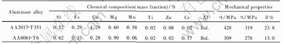
Table 2 Welding tool size and welding parameters used in experiments
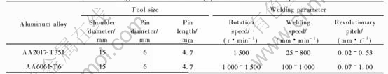
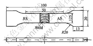
Fig.1 Configuration and size of tensile specimens (unit: mm)
welded at different revolutionary pitches, including typical photographs (Figs.2(a) and (b)) and detailed data (Fig.2(c)). In this figure, the rupture location means the distance between the rupture surface and the weld center along the centerline of the joint cross-section.
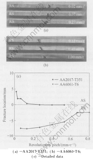
Fig.2 Rupture locations of joints of two aluminum alloys
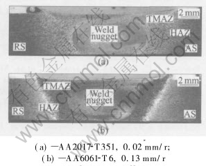
Fig.3 Cross sections of defect-free joints of two aluminum alloys
Regarding AA2017-T351, some joints are ruptured on the AS, the rupture locations are not far distant from the weld center, and the rupture surfaces appear as an oval contour of the weld nugget, while other joints are ruptured in the weld center(see Figs.2(a) and (c)).
With respect to AA6061-T6, all the joints are ruptured on the RS. Some rupture locations are distant from the weld center and the rupture surfaces are inclined at a certain degree to the bottom surfaces of the joints, while other rupture locations are near the weld center (see Figs.2(b) and (c)).
It should be noted that the rupture locations of the joints change with the FSW parameters. As the revolutionary pitch increases, the rupture locations of the joints move towards the weld center, but the rupture in the weld center is only presented in the AA2017-T351 joints (see Fig.2(c)).
These results indicate that the rupture locations of the joints are different for different aluminum alloys, and they are influenced by the FSW parameters.
3.2 Decisive factors of rupture locations
The rupture locations of the joints are dependent on the internal structures of the joints. When the joints are free of defects, as shown in Fig.3, a large number of joints are ruptured according to the microhardness distributions in the joints, e.g. AA6061-T6 joints, but a small number of joints are ruptured independently of them, e.g. AA2017-T351 joints.
In the AA2017-T351 joints, there are two low-hardness zones on both sides of the weld center (see Fig.4(a)). However, it is strange that the joints are ruptured in neither low-hardness zone. In detail, the joints are ruptured in the weld nugget adjacent to the thermo-mechanically affected zone (TMAZ) on the RS, i.e. at or near the interface between the weld nugget and the TMAZ on the AS (see Fig.3(a)), and the plastic deformation produced in the joints are very low. The reason for this may be that a significant difference in the microstructure exists between the weld nugget and the TMAZ. The weld nugget is composed of fine, equiaxed and recrystallized grains, while the TMAZ is composed of coarse, bent and recovered grains. Therefore, the interface between the weld nugget and the TMAZ is clearly visible and becomes a weaker region or location in the joint, and thus the fracture occurs at this interface during the tensile testing.
In the AA6061-T6 joints, there are also two low-hardness zones on both sides of the weld center (see Fig.4(b)), and they correspond to the two HAZs in the joint (see Fig.3(b)) because of the dissolution or growth of strengthening precipitates in such zones during the welding thermal cycle. The minimum hardness value is present in the low-hardness zone on the RS, accordingly the joints are ruptured in the HAZ on the RS. The distance between the minimum-hardness location and the weld center decreases as the revolutionary pitch increases, consequently the rupture locations of the joints move towards the weld center.
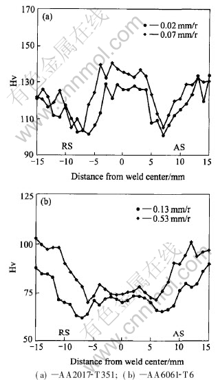
Fig.4 Microhardness profiles in joints of two aluminum alloys
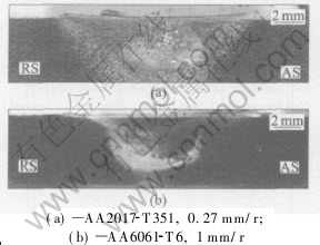
Fig.5 Defects in joints of two aluminum alloys
On the other hand, when welding defects are present in the joints, the rupture locations of the joints are significantly dependent on these defects. Fig.5 shows the welding defects in the joints of the two aluminum alloys. In the AA2017-T351 joints, the defects are composed of many voids and distributed in the middle of the weld (see Fig.5(a)), therefore the joints with defects are fractured in the weld center. In the AA6061-T6 joints, the defects are located in the lower parts of the joints. They are narrow and long, but smaller than the diameter of the tool pin (see Fig.5(b)). During the tensile tests, the joints are ruptured through the tips of the defects. Because the defect length is smaller than the pin diameter, the rupture locations are not far distant from the weld center. Moreover, the defects slope slightly from the RS to the AS, therefore the joints tend to rupture on the RS.
4 CONCLUSIONS
1) The rupture locations of the joints are different for the two aluminum alloys selected in this study, and they are influenced by the FSW parameters or internal structures of the joints.
2) When the joints are free of welding defects, the AA2017-T351 joints are ruptured in the weld nugget adjacent to the TMAZ on the AS, and the rupture surfaces appear as oval contours of the weld nugget; the rupture locations of the AA6061-T6 joints are in the HAZ on the RS, and the rupture surfaces are inclined at a certain degree to the bottom surfaces of the joints.
3) When welding defects are present in the joints, the AA2017-T351 joints are ruptured in the weld center, while the AA6061-T6 joints are ruptured on the RS near the weld center.
REFERENCES
[1]Campbell G, Stotler T. Friction stir welding of armor grade aluminum plate[J]. Weld J, 1999, 78: 45-47.
[2]Johnsen M R. Friction stir welding takes off at Boeing[J]. Weld J, 1999, 78: 35-39.
[3]Dawes C J, Thomas W M. Friction stir process welds aluminum alloys[J]. Weld J, 1996, 75: 41-45.
[4]Liu H J, Fujii H, Maeda M, et al. Friction stir welding characteristics of two aluminum alloys[J]. Trans Nonferrous Met Soc China, 2003, 13 (5): 1108-1111.
[5]Liu H J, Fujii H, Maeda M, et al. Study of friction stir welding of AA5083 aluminum alloy[J]. Trans Nonferrous Met Soc China, 2003, 13 (Special): 14-17.
[6]Okamura H, Aota K, Sakamoto M, et al. Behavior of oxide during friction stir welding of aluminum alloy and its influence on mechanical properties[J]. Q J Jap Weld Soc, 2001, 19: 446-456.
[7]Mahoney M W, Rhodes C J, Flintoff J G, et al. Properties of friction stir welded 7075-T651 aluminum[J]. Metall Mater Trans A, 1998, 29: 1955-1964.
[8]Svensson L E, Karlsson L, Larsson H, et al. Microstructure and mechanical properties of friction stir welded aluminum alloys with special reference to AA5083 and AA6082[J]. Sci Technol Weld Join, 2000, 5: 285-296.
[9]Strombeck A V, Santos J F D, Torster F, et al. Fracture toughness behavior of FSW joints on aluminum alloys[A]. Proc 1st Int Friction Stir Welding Symp[C]. California, USA, 1999.
[10]Magnusson L, Kallman L. Mechanical properties of friction stir welds in thin sheet of aluminum 2024, 6013 and 7475[A]. Proc 2nd Int Friction Stir Welding Symp[C]. Gothenburg, Sweden, 2000.
[11]Sato Y S, Kokawa H. Distribution of tensile property and microstructure in friction stir weld of 6063 aluminum[J]. Metall Mater Trans A, 2001, 32: 3023-3031.
[12]Sato Y S, Urata M, Kokawa H, et al. Retention of the grained microstructure of equal channel angular pressed aluminum alloy 1050 by friction stir welding[J]. Scripta Mater, 2001, 45: 109-113.
[13]Field D P, Nelson T W, Hovanski Y, et al. Heterogeneity of crystallographic texture in friction stir welds of aluminum[J]. Metall Mater Trans A, 2001, 32: 2869-2877.
[14]Flores O V, Kennedy C, Murr L E, et al. Microstructural issues in a friction stir welded aluminum alloy[J]. Scripta Mater, 1998, 38: 703-708.
[15]Jin H, Saimoto S, Ball M, et al. Characterization of microstructure and texture in friction stir welded joints of 5754 and 5182 aluminum alloy sheets[J]. Mater Sci Technol, 2001, 17: 1605-1614.
[16]Sato Y S, Urata M, Kokawa H, et al. Effect of friction stir processing on microstructure and hardness profile of equal channel angular pressed aluminum alloy 1050[A]. Proc 7th Int Welding Symp[C]. Kobe, Japan, 2001.
(Edited by YUAN Sai-qian)
Received date: 2004-09-20; Accepted date: 2005-01-26
Correspondence: LIU Hui-jie, Professor, PhD; Tel/Fax: +86-451-86418146; E-mail: liuhj@hope.hit.edu.cn

