Boost PFC变换器快时标分岔分析及其双积分滑模控制
郑连清,鲁思男,申滔,陆治国
(重庆大学 输配电装备及系统安全与新技术国家重点实验室,重庆,400044)
摘要:为了分析峰值电流型Boost PFC(power factor correction)在快时标下的非线性现象,建立Boost PFC变换器的离散迭代映射,并基于此映射推导其状态转移矩阵的表达式,得到系统分岔的条件,通过仿真观察系统电感电流在输入电压周期内出现的间歇性分岔和混沌现象。为了避免分岔,使系统稳定工作在单周期态,采用双积分滑模的控制方法。仿真结果表明:与常规的斜坡补偿法相比,双积分滑模法不需要施加外部扰动,且具有良好的鲁棒性,在有效地避免因输入电压变化所产生的分岔现象的同时,让Boost PFC具有较高的功率因数(PF),且算法简单,易于实现,对PFC变换器的分岔控制提供了借鉴。
关键词:功率因数校正;快时标;分岔;双积分滑模
中图分类号:TM46 文献标志码:A 文章编号:1672-7207(2013)02-0587-06
Analysis of fast-scale bifurcation in Boost PFC converters and double integral sliding mode control
ZHENG Lianqing, LU Sinan, SHEN Tao, LU Zhiguo
(State Key Laboratory of Power Transmission Equipment & System Security and New Technology,
Chongqing University, Chongqing 400044, China)
Abstract: In order to analyze fast-scale nonlinear phenomenon in Boost PFC in peak-current control mode, a discrete iterative map for Boost PFC converter was derived, and the expression of the state transition matrix was obtained according to this map. In addition, the bifurcation boundary of the system was also derived. Then the simulation was presented to show the intermittent bifurcations and chaos phenomenon of the inductor current in one input voltage cycle. To avoid bifurcations, a double integral sliding mode control was adopted to make the system operate stably in single-period state. Compared with slope compensation, a conclusion can be drawn that double integral sliding mode control can achieve good robustness without imposing external disturbance, and avoid bifurcations caused by variation of the input voltage effectively, which can also attain high power factor (PF) with simple algorithm. The new method is easy to realize and can provide reference for bifurcation control in PFC converters.
Key words: power factor correction; fast-scale; bifurcation; double integral sliding mode control
随着非线性负载广泛应用于电网中,产生的谐波污染和低功率因数问题也日趋严重。为了解决这一问题,功率因数校正(PFC)是一种有效的方法。由于开关器件自身的特性和反馈控制环节的引入,使得Boost PFC成为一种强非线性系统[1]。近年来,国内外学者采用非线性动力学对Boost PFC变换器进行了研究并取得了一些成果[1-5]。已有的研究发现PFC变换器中同时存在2个频率,即开关频率和工频,这使得PFC变换器中可能出现2种分岔类型:快时标分岔(fast-scale)和慢时标(slow-scale)分岔,它们分别对应发现在开关频率和工频附近的分岔[2]。慢时标分岔一般以负载电阻和输出电容为分岔参数,而快时标分岔常以电感和输入电压有效值为分岔参数[3]。上述2种分岔会在变换器处于某些参数下出现,表现为倍周期分岔、边界碰撞分岔甚至混沌现象[4-5]。这些现象的存在会严重影响PFC变换器的工作性能。功率因数校正技术中,峰值电流型Boost PFC是其中最为常见的。本文作者基于峰值电流型Boost PFC建立了其离散迭代映射,从理论上分析了变换器出现快时标分岔的条件,并借鉴近几年来国内外滑模控制的研究成果[6-10],采用双积分滑模对其分岔现象进行控制。双积分滑模控制通过增加控制器的阶数改善了系统的稳态误差并降低了滑模控制中的抖振现象,同时获得了较高的功率因素。
1 稳定性分析
图1所示为峰值电流型Boost PFC的电路[11]。
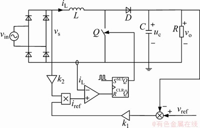
图1 峰值电流型Boost PFC原理图
Fig.1 Schematic of Boost PFC under peak-current control mode
图1中:vin为输入的工频电压;vs为整流后的电压;iL为电感电流;uc为电容两端的电压;vo为输出电压;Vref为参考电压;iref为参考电流;k1和k2为控制增益参数,其中:
 (1)
(1)
 (2)
(2)
Vm为输入电压的峰值;ω=100π。
该变换器工作在连续模式,在第n个开关周期内,输入电压为:

其中:T为开关周期,由于开关频率远远大于电源频率,可以近似认为一个开关周期内输入电压不变,记 ,
, 。
。
定义状态向量 ,则有:
,则有:

其中:
 ;
; ;
; ;Vsn=Vmp。
开关条件所对应的临界状态平面为:

在第n个开关周期内导通阶段的状态转移矩阵表示为 ,截止阶段为
 ,其中dn为第n个周期的占空比。定义跳跃矩阵[12]:

其中:I为二阶单位矩阵;n通过对h(x,t)求梯度得到,即 ,因此第n个开关周期的PFC变换器状态转移矩阵为:

对应的第n个开关周期稳态解可以通过以下方程组求解得到。

其中:Xen和Dn为系统第n个开关周期的稳态解和占空比。
对于采用峰值电流控制的变换器系统,满足时间常数(τ=RC)远远大于T,此时系统任意一个开关周期内对应的状态转移矩阵存在2个特征值,一个特征根λ1接近1,另一个为

若变换器系统是稳定的,则状态转移矩阵的特征值全部位于单位圆内。分析上式可知:当 时,系统处于临界状态,并随着输入电压的减小进入不稳定态,反之,系统则进入稳定态。
2 仿真验证分析
选取系统参数如下:Vm=110 V,Vref=220 V,L=2 mH,C=470 μF,R=100 Ω,k1=0.02,k2=0.03,T=20 μs。
图2所示为在t∈[0.050 s,0.060 s]时1/2个工频周期内的电感电流仿真波形。可见:在输入电压过0 V处,电感电流发生了快时标分岔,在局部放大曲线(图3)中发现iL分别在0.052 8 s和0.057 8 s这两个时刻发生了分岔。
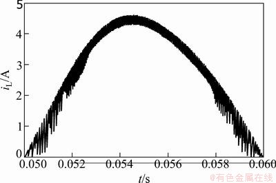
图2 电感电流iL的时域波形
Fig.2 Time-domain waveforms of inductor current iL
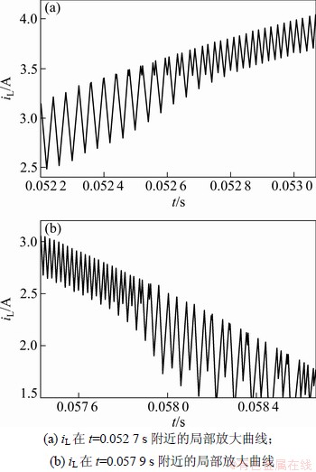
图3 电感电流iL的局部放大曲线
Fig.3 Close-up curve of inductor current iL
以开关周期T为采样间隔,基于频闪映射的原理做出电感电流的频闪采样曲线。图4所示为对应于图2的频闪采样曲线。由图4可见:随着输入电压的增大,电感电流从混沌态变为二周期态,在0.052 8 s处进入单周期态,然后在0.057 8 s处再次进入二周期态,最后发生边界碰撞分岔以非光滑的方式直接变为混沌态。
改变电路参数,降低输入电压,令Vm=55 V,给出此时的电感电流频闪采样曲线,如图5所示。其中图5(b)纵坐标M表示N次谐波幅值基波电流幅值的百分比(%)。在整个1/2个工频周期内电感电流都处于快时标不稳定状态,总谐波失真率(THD)明显增大。
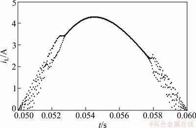
图4 电感电流iL的频闪采样曲线
Fig.4 Stroboscopic waveform of inductor current iL
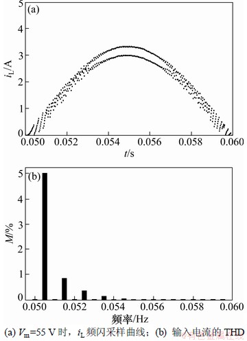
图5 电感电流iL的频闪采样曲线和THD
Fig.5 Stroboscopic waveform and THD of inductor current iL when Vm=55 V
仿真结果表明:当输入电压减小时,系统从间歇性分岔进入了混沌态,验证了稳定性分析中的结论。
3 双积分滑模控制
3.1 控制器的设计
双积分滑模控制的Boost PFC原理如图6所示。
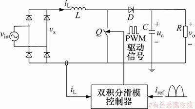
图6 双积分滑模控制的Boost PFC原理图
Fig.6 Schematic of Boost PFC with double integral sliding mode control
此控制器采用电流误差x1,电流误差的积分x2和其双重积分x3作为变量。状态变量定义如下[13]:
 ,
, ,
, (3)
(3)
令控制信号u为1或0,u=1表示开关导通,u=0表示开关断开。滑模面定义为:

其中:a,b和c为滑模系数。S的一阶导数为:

 ;
; ;
;
其中: 。鉴于滑模控制的不变性,有S=0和
 ,因此,
,因此,
 (4)
(4)
等效控制[14]中,用一个连续信号 来代替离散信号
 ,其中0<<1。
将式(3)代入式(4)中可得:
 (5)
(5)
解式(5)可得:
 (6)
(6)
其中: ;
; 。式(6)即为Boost PFC的通用控制律。
由李雅普诺夫稳定性分析确定滑动模态存在条件。定义李雅普诺夫函数为

要使系统运行在滑动模态,必须满足: [15]。
[15]。
当 ,
, 时,有
时,有
 (7)
(7)
当 ,
, 时,有
时,有
 (8)
(8)
合并式(7)和式(8),可以得到:

上式即为系统滑动模态存在的条件。
3.2 滑模系数的选择
将式(6)变形为,
 (9)
(9)
再把式(9)转化为频域表示,
 (10)
(10)
图7所示为式(10)的传递函数框图。
选取52°的相角裕度设计补偿环节,利用Matlab绘出其伯德图(如图8所示),同时考虑滑动模态的存在条件,最后确定α=2×10⁵,β=4×10⁸。
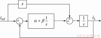
图7 双积分滑模控制的电流环框图
Fig.7 Block diagram of current loop under double integral sliding mode control
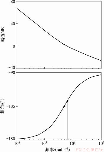
图8 双积分滑模控制的电流环伯德图
Fig.8 Bode diagram of current loop under double integral sliding mode control
4 仿真结果
保持主电路参数不变,当Vm=110 V时,Boost PFC的电感电流波形及总谐波失真率(THD)如图9所示。
降低输入电压,当Vm=55 V时,仿真结果如图10 所示。从频闪采样图中看到,电感电流没有出现分岔和混沌现象,且THD从0.55%上升到0.70%,功率因数保持在0.999。
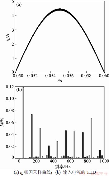
图9 Vm=110 V时,电感电流的频闪曲线和THD
Fig.9 Stroboscopic waveform and THD of inductor current when Vm=110 V
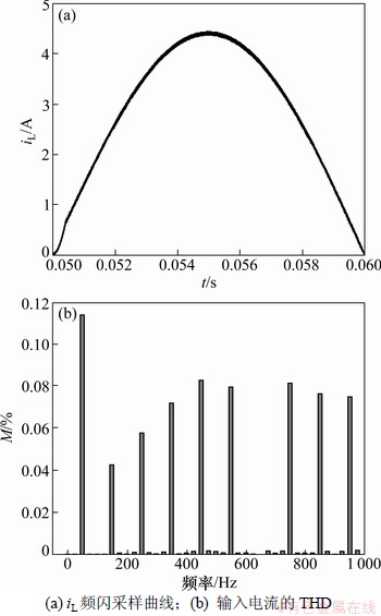
图10 Vm=55 V时,电感电流的频闪曲线和THD
Fig.10 Stroboscopic waveform and THD of inductor current when Vm=55 V
5 结论
(1) 建立了峰值电流型Boost PFC离散迭代映射,分析了随着输入电压的减小,系统发生倍周期分岔,但并未充分发展,而是以非光滑的方式直接进入混沌态。然后利用时域图和频闪采样图,验证了上述分析。最后,采用双积分滑模法实现了对Boost PFC的控制,在不同的参数条件下都有效地避免了混沌现象的发生,并使Boost PFC获得了0.999的高功率因素。
(2) 双积分滑模控制法在分岔控制中具有以下特点:不需要改变系统参数或施加外部扰动;使PFC获得较高的功率因素;具有很强的鲁棒性。鉴于该法的诸多特点,保证了Boost PFC在不同参数条件下运行的稳定性和可靠性。
参考文献:
[1] 马西奎, 李明, 戴栋, 等. 电路电子与系统中的复杂行为研究综述[J]. 电工技术学报, 2006, 21(12): 1-16.
MA Xikui, LI Ming, DAI Dong, et al. Reviews of research on complex behavior of power electronic circuits and systems[J]. Transactions of China Electrotechnical Society, 2006, 21(12): 1-16.
[2] 邹建龙, 马西奎. 功率因数校正Boost变换器中快时标分岔的实验研究[J]. 中国电机工程学报, 2008, 28(12): 38-43.
ZOU Jianlong, MA Xikui. Experimental study of fast-scale bifurcations in PFC boost converters[J]. Proceedings of the CSEE, 2008, 28(12): 38-43.
[3] 邹建龙, 马西奎, 杨宇. 功率因数校正Boost变换器中慢时标分岔的影响因素分析与分岔控制[J]. 中国电机工程学报, 2010, 30(3): 1-7.
ZOU Jianlong, MA Xikui, YANG Yu. Influencing factors to slow-scale bifurcation in PFC boost converters and bifurcation control[J]. Proceedings of the CSEE, 2010, 30(3): 1-7.
[4] Tes C K, Dranga O, Iu H H C. Bifurcation analysis of a power-factor-correction Boost converter: Uncovering fast-scale instability[C]//Proceedings of the 2003 International Symposium on Circuits and Systems. Bangkok, 2003: 312-315.
[5] Wu X Q, Tse C K, Dranga O, et al. Fast-scale instability of single-stage power-factor-correction power supplies[J]. Circuits and Systems, 2006, 53(1): 204-213
[6] Tan S C, Lai Y M, Tse C K, et al. Indirect sliding mode control of power converters via double integral sliding surface[J]. IEEE Trans Power Electron, 2008, 23(2): 600-611.
[7] Guo L P, Hung J Y, Nelms R M. Comparative evaluation of sliding mode fuzzy controller and PID controller for a boost converter[J]. Electric Power Systems Research, 2011, 81: 99-106.
[8] Wai R J, Shih L C. Design of voltage tracking control for DC-DC boost converter via total sliding-mode technique[J]. IEEE Transaction on Industrial Electronics, 2011, 58(6): 2502-2511.
[9] Pan P L, Chern T L, Kuang J H. Sliding Mode Control for PWM Single Phase Boost Power Factor Correction[C]//5th IEEE Conference on Industrial Electronics and Applications. Taichung, 2010: 82-87.
[10] 陈帝伊, 申滔, 马孝义. 参数不定的旋转圆盘在有界扰动下混沌振动的滑模变结构控制[J]. 物理学报, 2011, 60(5): 1-8.
CHEN Diyi, SHEN Tao, MA Xiaoyi. Sliding mode control of chaotic vibrations of spinning disks with uncertain parameter under bounded disturbance[J]. Acta Phys Sin, 2011, 60(5): 1-8.
[11] ZHANG Hao, MA Xi-kui, XUE Bian-ling, et al. Study of intermittent bifurcations and chaos in boost PFC converters by nonlinear discrete models[J]. Chaos, Solitons and Fractals, 2005, 23(2): 431-444.
[12] 雷涛, 张晓斌, 林辉. 峰值电流控制的PFC变换器快时标分岔控制[J]. 电工技术学报, 2010, 25(8): 91-98.
LEI Tao, ZHANG Xiaobin, LIN Hui. Control of fast time scale bifurcations in PFC converters based on peak current control[J]. Transactions of China Electrotechnical Society, 2010, 25(8): 91-98.
[13] Tan S C, Lai Y M, Tes C K, et al. A double-integral type of indirect sliding mode controllers for power converter[C]//Power Electronics Specialists Conference. Orlando, 2007: 177-183.
[14] Chu G, Tan S C, Tse C K, et al. General Control for Boost PFC Converter from a Sliding Mode Viewpoint[C]//39th IEEE Power Electronic Specialists Conference (PESC 08). Rhodes, 2008: 4452-4456.
[15] JIAO Yan-ping, LUO Fang-lin. Quasi sliding mode controller for single phase PFC boost converter[C]//5th IEEE Conference on Industrial Electronics and Applications. Taichung, 2010: 2099-2103.
(编辑 杨幼平)
收稿日期:2012-03-12;修回日期:2012-05-09
基金项目:输配电装备及系统安全与新技术国家重点实验室自主研究项目(2007DA10512711205)
通信作者:郑连清(1964-),男,浙江金华人,博士,教授,从事电力电子技术与应用研究;电话:13896145146;E-mail:lqzheng64@cqu.edu.cn

