
J. Cent. South Univ. (2018) 25: 448-460
DOI: https://doi.org/10.1007/s11771-018-3749-0

Prediction of upper limit position of bedding separation overlying a coal roadway within an extra-thick coal seam
YAN Hong(�Ϻ�)1, ZHANG Ji-xiong(�ż���)1, LI Lin-yue(���֫h)2,FENG Rui-min(������)3, LI Tian-tong(����ͮ)1
1. State Key Laboratory of Coal Resource and Safe Mining, Key Laboratory of Deep Coal Resource Mining of Ministry of Education of China (China University of Mining & Technology), Xuzhou 221116, China;
2. Guizhou Xinlian Blasting Engineering Group Co., Ltd, Guiyang 550002, China;
3. Department of Chemical and Petroleum Engineering, University of Calgary, Calgary T2N 1N4, Canada
 Central South University Press and Springer-Verlag GmbH Germany, part of Springer Nature 2018
Abstract: Failure of the surrounding rock around a roadway induced by roof separation is one major type of underground roof-fall accidents. This failure can especially be commonly-seen in a bottom-driven roadway within an extra-thick coal seam (��bottom-driven roadway�� is used throughout for ease of reference), containing weak partings in their roof coal seams. To determine the upper limit position of the roof interlayer separation is the primary premise for roof control. In this study, a mechanical model for predicting the interlayer separation overlying a bottom-driven roadway within an extra-thick coal seam was established and used to deduce the vertical stress, and length, of the elastic, and plastic zones in the rock strata above the wall of the roadway as well as the formulae for calculating the deflection in different regions of rock strata under bearing stress. Also, an approach was proposed, calculating the stratum load, deflection, and limiting span of the upper limit position of the interlayer separation in a thick coal seam. Based on the key strata control theory and its influence of bedding separation, a set of methods judging the upper limit position of the roof interlayer separation were constructed. In addition, the theoretical prediction and field monitoring for the upper limit position of interlayer separation were conducted in a typical roadway. The results obtained by these two methods are consistent, indicating that the methods proposed are conducive to improving roof control in a thick coal seam.
Key words: extra-thick coal seam; bedding separation; coal roadway; roof fall; mechanical model
Cite this article as: YAN Hong, ZHANG Ji-xiong, LI Lin-yue, FENG Rui-min, LI Tian-tong. Prediction of upper limit position of bedding separation overlying a coal roadway within an extra-thick coal seam [J]. Journal of Central South University, 2018, 25(2): 448�C460. DOI: https://doi.org/10.1007/s11771-018-3749-0.
1 Introduction
In underground coal mines, it is necessary to excavate a mining roadway for access, ventilation, coal conveying, etc. before the formation of a working face. The stability of a mining roadway, including its roof, two ribs, and floor, directly influences mine production and, more importantly, affects the safety of underground operators. For example, the frequent sudden roof collapse is one kind of disaster caused by unstable surrounding rocks [1�C4]. By virtue of the accident inquiry system of the Chinese State Administration of Work Safety, it is statistically found that roof accidents are respectively 8 and 49 times, which are more likely than water in-rush, and fire accidents in Chinese coal mines from 2001 to 2010. In addition, as reported by the Mine Safety and Health Administration (MSHA), in the USA, the death toll from roof accidents accounts for approximately 70% of all underground deaths in the USA [5]. Similarly, in India, about 61.1% of accidents in coal mines are due to roof caving: roof accidents and casualties respectively accounted for 43.6% and 41.9% of the totals from 1995 to 2000 [6, 7].
In China, the reserve of thick/ultra-thick coal seams accounts for 45% of total recoverable amount of coal. These coal seams are mainly distributed in Shanxi, Shaanxi, Mongolia, Ningxia, Gansu, Xinjiang etc [8, 9]. Among the roof accidents induced by mining roadways with complex characteristics, such as compound roof, soft coal seam, and high stresses, the accidents resulting from roof separation-instability due to driving a bottom coal roadway in extra-thick coal seams have been one of the most frequently occurred underground disasters. These accidents have shown the worst casualty rates due to their complexity. For instance, the excavation section of the roadway is large; the roof is made up of a thick coal seam and thin, soft, weak partings; there are widely-developed joint fissures in the coal seam [10�C12], as shown in Figure 1. Thereby, effective control of the roof separation of the roadway in extra-thick coal seams can prevent the development of roof failures on the premise that the upper limiting position of interlayer separation can be reasonably predicted in advance.
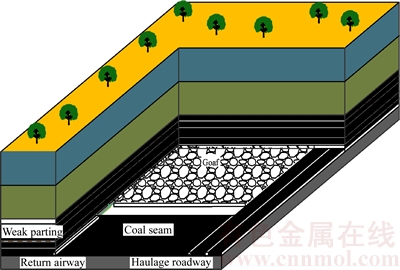
Figure 1 Layout of coal roadway within an extra-thick coal seam
Roof separation is a kind of separation phenomenon appearing in roof strata or adjacent rock strata during roadway excavation, as shown in Figure 2. Except for the physico-mechanical properties of roof coal-rock strata, the separation is also greatly affected by other factors, such as roadway section, burial depth, and geological conditions [13�C15]. Many researchers have investigated the distribution of roof separation from different perspectives, including mining science, coal field geology, engineering mechanics, etc [16�C18]. Some scholars proposed that roof separation arises when the lower stratum is separated from the upper strata, so that the strength thereof is gradually reduced from bottom to top until the strata are bent. This is owing to the effect of gravity stress, the normal tensile stress on the coal seam, and that the weak parting exceeds the normal tensile strength of the bedding surface of the strata [19, 20]. With the development of research into roadway stability, the concepts of temporary roof separation [21] and periodic separation have been introduced [22]. In recent years, monitoring devices related to roof separation have been developed, such as the mechanical roof separation indicator, on-line monitoring systems for separation, stratum probing radar, and acoustic emission and reception device technologies [23, 24].
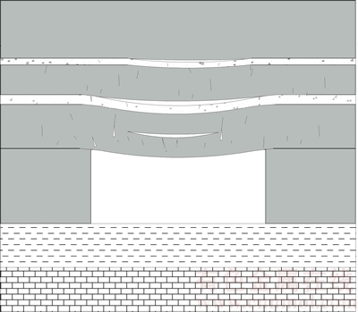
Figure 2 Schematic diagram of roof separation in coal roadways with extra thick coal seam
According to the non-linear contact theory, ZHANG et al [25] simulated the characteristics of roof separation in layered roadways by ANSYS software. QIAN et al [26] established a mechanical model for the stability of roof strata to derive the instability criterion for roof separation by combining macroscopic damage mechanical methods. WU et al [27] studied the stability and separation of a complex roof in a deep roadway and considered that, initially, the plastic separation plays the main role, while the later stage is mainly based on interlayer separation. KWON et al [28] proved that the bedding separation exerts an important influence on roof stability of underground roadways. HEBBLEWHITE et al [13] undertook detailed field observations and monitoring of roof separation values during different mining activities on a typical roadway with laminated and weak roof strata. The aforementioned studies mainly focused on the following aspects: the characteristics of roof separation in compound roadways, separation monitoring devices, stress distribution, etc. However, bottom-driven roadways within an extra- thick coal seam have rarely been investigated. The authors determined the upper limit position of the interlayer separation overlying a bottom-driven roadway within an extra-thick coal seam by establishing a mechanical model for the roof interlayer separation therein to provide guarantees of reasonable control technologies for roadways in thick coal seams.
2 Mechanical model for predicting bedding separation of a roadway roof in an extra-thick coal seam
The failure region of the coal bottom-driven roadway roof within an extra-thick coal seam mainly consists of the coal seam and soft and weak partings. After excavating the roadway, part of the interfaces between the coal and rock in the roof is separated owing to the differences in the physical and mechanical properties of the roof strata and coal seams. When the measured data used for predicting separations in some regions are greater than certain limit values, roof strata gradually become unstable, and even fall down. To determine the upper limit position of roof interlayer separation, a mechanical model representing the interlayer separation of overlying a bottom-driven roadway within an extra-thick coal seam was constructed as shown in Figure 3.
It is assumed that there are n layers above the roof, namely, S1, S2, S3, ��, Si, ��, Sn in sequence, and the uniform loading on the overlying strata is q.
Combined with key strata theory [29], the strata below the  above the roof are included and then the load borne by the
  stratum is:
 (1)
(1)
Considering the stratum, the load carried by the  stratum is:
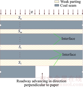
Figure 3 Mechanical model for interlayer separation of a roadway roof in an extra-thick coal seam
 (2)
(2)
The shear stress ��xy is produced by roadway excavation, and the surrounding rock stress is redistributed. The vertical stress generated by the strata above the coal rib increases to form abutment pressure areas. Figure 4 shows the stress distribution on the stratum, where km is a stress concentration coefficient. It can be seen that the greater the distance between the rock stratum and the surface of the roadway roof, the smaller the value of km, where km��1.
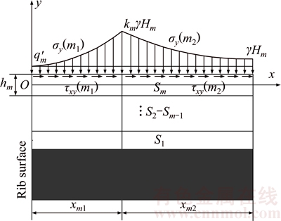
Figure 4 Stress distribution on  stratum above wall of roadway
To calculate the vertical stresses in the plastic, and elastic zones, namely, ��y(m1) and ��y(m2), and their length xm1 and xm2, the following fundamental assumptions are given:
1) The lateral stresses in plastic, and elastic zones ��x(m1) and ��x(m2) are uniformly distributed, and they are independent of the thickness of the stratum.
2) The relationship between the vertical stresses, ��y(m1) and ��y(m2) and the corresponding lateral stresses ��x(m1) and ��x(m2) in the plastic, and elastic zones are as follows:
a) In the plastic zone:
 (3)
(3)
b) In the elastic zone: when, and only when,
x=xm1 or x=xm1+xm2, ��x(m2)=��m��y(m2) (4)
3) The vertical stresses in both plastic, and elastic zones, namely ��y(m1) and ��y(m2) are the correlation function of x. Moreover, the relationship with the shear stress ��xy(m1) and ��xy(m2) on the interface meets the following conditions:
 (5)
(5)
4) Owing to the vertical stress in the elastic zone ��y(m2) reducing successively with a negative exponential relationship, its function can be approximated as a quadratic:
 (6)
(6)
where  is the minimum load distributed vertically in the plastic zone; hm is the thickness of the
  stratum; ��m is the lateral stress coefficient of the stratum;
  and
and  are the internal friction angle and cohesion of the interface between the upper adjacent seams of the stratum respectively; Hm is the vertical distance between the ground surface and thestratum; and

 are coefficients.
To calculate the vertical stresses in the plastic zone ��y(m1), as shown in Figure 5, a finite element is selected as follows:
 (7)
(7)
Substituting Eqs. (3) and (4) into Eq. (7), it can be found that:
 (8)
(8)
Then it can be solved by using Eq. (8) to give:
 (9)
(9)
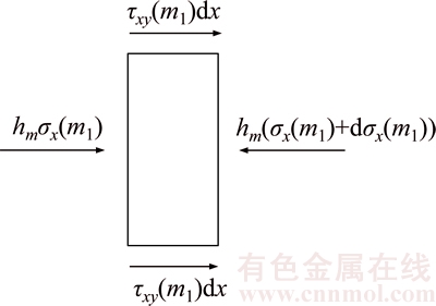
Figure 5 Stresses on a finite element in  stratum
At the boundary of the roadway, namely x=0, ��y(m1)�Cq��m, we have:
 (10)
(10)
When x=xm1, ��y(m1)=km��Hm, it can be seen, through Eqs. (9) and (10), that:
 (11)
(11)
To calculate the vertical stresses in the elastic zone ��y(m2), the shear stress ��xy(m2) and the length of the elastic zone xm2, it can be seen from elastic mechanics that the Airy stress function f should meet the general solution and compatibility equation of the homogeneous differential equations, namely:
 (12)
(12)
(a) When x=xm1, ��y(m2)=km��Hm;
(b) When x=xm1+xm2, ��y(m2)=��Hm;
(c)
 .
.
Combining conditions (a), (b), (c) and Eq. (6), gives:
 (13)
(13)
Substituting Eq. (13) into Eq. (6) gives:

 (14)
(14)
Substituting Eq. (12) into Eq. (14) gives:


 (15)
(15)
Fundamental Assumption 1 indicates that ��x(m2) is uniformly distributed, which is independent of the thickness of the stratum, so functions f1(x) and f2(x) can be expressed as follows:
 (16)
(16)
Substituting Eq. (16) into Eq. (15) gives:


 (17)
(17)
The shear stress in the elastic zone on the interface of the upper surface of the stratum and the adjacent strata is:
 (18)
(18)
At the junction of the limit equilibrium, and elastic zones, namely x=xm1, we have ��xy(m1)�C��xy(m2). Thereby, the length of the elastic zone can be obtained by substituting ��xy(m1) in Eq. (11) into Eq. (18), namely:
 (19)
(19)
The stratum was selected for stress analysis. The lower stratum in the elastic zone acted as a ground model, where  is the foundation coefficient; lm is the length of the stratum under the effect of uniform load.
Owing to the fact that the load on the rock beam of the stratum is bilaterally symmetrical, the authors only need to analyze half of the model (see Figure 6).
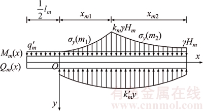
Figure 6 Stress on one side of rock beam in stratum
The differential equation for the deflection in different areas of thestratum is:
 (20)
(20)
After calculation, the deflections in different areas are as follows:
 (21)
(21)
Based on the boundary conditions at  and the continuity conditions between different areas, it can be found that:
 (22)
(22)
The specific values of the deflection parameters in each area of the stratum, including Am1, Bm1, Cm1, Dm1, Am2, Bm2, Cm2, Dm2, Cm3 and Dm3 can be solved by using Eq. (22), and then these values are substituted into Eq. (21) to obtain the concrete form of the deflection function in all areas of the stratum.
The equation for ��y(m1), ��y(m2), xm1, xm2, y1(x), y2(x), and y3(x) can be obtained according to the aforementioned results, which is conducive to determining the rock strata deformation and separation values of the mining roadway under a thick coal roof. However, due to the fact that the parameters are influenced by many complex factors, there are some limitations of determining the upper limit position of roof interlayer separation. In accordance with a large number of field monitoring results, after excavation of the roadway, the lateral stress on the roof strata is much lower than the corresponding value on the adjacent working face during mining. As a result, the stress has a limited effect on roof interlayer separation. On this basis, the stratum can be further simplified as a simply-supported beam with unit width (see Figure 7).
During analysis of the force on the stratum, the forces on the stratum and the  stratum are calculated. The loading condition for generating separation in roof strata is the corresponding load borne by the stratum and (qn)m>(qn+1)m.
The differential equation for the deflection in the stratum can be further obtained as follows:
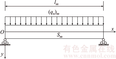
Figure 7 Model for stratum within roof above a coal roadway
 (23)
(23)
Owing to the maximum deflection of simply supported beam occurring at its midpoint, the maximum value is:
 (24)
(24)
Then the second condition for roof separation is: as for the adjacent strata, the maximum deflection of the lower rock stratum is greater than that of the stratum. Taking the stratum as an example, 
Evidently, the normal stress of an arbitrary point in the stratum �� is:
 (25)
(25)
where y is the distance between the point and the neutral axis; Im is the moment of inertia about the symmetric neutral axis; hm is the thickness of the stratum; and M is the bending moment at the section in which the point is located.
The maximum bending moment of simply supported beam is at the midpoint of the beam, namely  and then the maximum tension stress at this point ��max is:
 (26)
(26)
The maximum tensile stress is regarded as the basis for strata fracture. Then when ��max reaches the ultimate tensile strength [��ms], the beam fractures at its mid-point, and the limiting span is:
 (27)
(27)
Comparing the limiting span of a rock beam and the width of the roadway, the third condition for separation in roof coal and rock seams is that the limiting span of the rock stratum containing the separation is greater than the width of the roadway, i.e., lmT>L.
In addition, based on the field monitoring results, the main zone influenced by the roof interlayer separation during mining on a bottom- driven roadway within an extra-thick coal seam was up to 6 m away, and the maximum influence distance was h0. Therefore, when the key stratum is beyond the scope influenced by the separation, namely hs>h0, the interlayer separation produced between the key stratum and its adjacent strata can be ignored in theoretical calculations. On the contrary, if the key stratum is within the scope influenced by the separation, i.e., hs>h0, it is necessary to consider the interlayer separation generated between the key stratum and its adjacent strata.
In the light of this analysis, it can be concluded that the method of judging the upper limit of the interlayer separation overlying the bottom-driven roadway within an extra-thick coal seam (Figure 8) is applicable.
3 Case study
3.1 Geological and production conditions
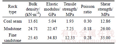
The analysis was conducted on the 29211 working face in the No. 9 coal seam of a mine in Shanxi, China. The thickness of the coal seam is 9.82 to 14.29 m, with a mean thickness of 12.39 m, as shown in Figure 9. In the working face, the fully mechanised top-coal caving mining technology was adopted and an all-collapse method was applied to roof management. Besides, the return airway of the working face is tunnelled along the floor of this coal seam, which is rectangular cross-section with dimensions: 5 m in width and 3.5 m in height, and the average mining depth of the roadway is 220 m. The coal seam including multilayer weak partings (see Figure 10), and the physico-mechanical parameters of the core samples collected by drilling from the surface of the roof to the rock stratum of the roadway are obtained by experimental tests, as shown in Table 1.
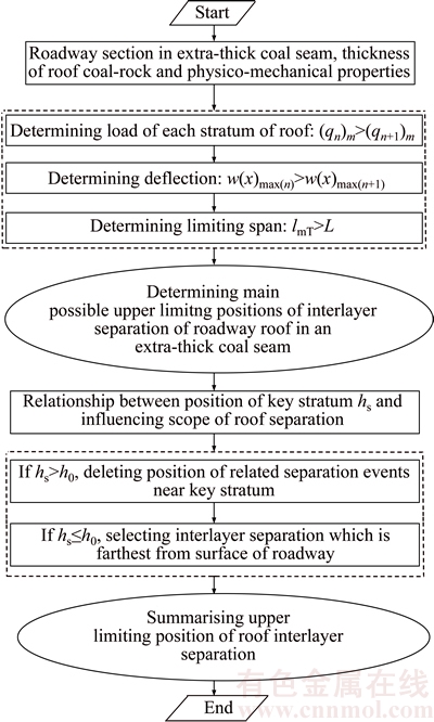
Figure 8 Method of determining upper limit of interlayer separation overlying a bottom-driven roadway within an extra-thick coal seam
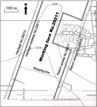
Figure 9 Layout of return airway No. 29211
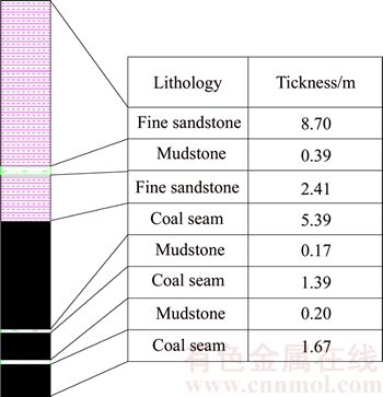
Figure 10 Coal seam and rock strata columnar section
Table 1 Physico-mechanical parameters
3.2 Theoretical determination of upper limiting position of roof interlayer separation
Using the method presented in Figure 7, namely the method for determining the upper limit of interlayer separation overlying the bottom-driven roadway within an extra-thick coal seam, the upper limit is determined in the following steps:
Step 1: Determining load
The load on the  stratum q1 is:

Taking the  stratum into consideration, the load borne by the stratum is:

Taking the 
 and
and strata into consideration, as shown in Figure 11, the strata S1, S2, S3 and S4 affect the load carried by the stratum, while the load on the stratum is unaffected by the stratum. Thus, the load borne by the stratum is (q4)1, and (q5)1<(q4)1, which meets the loading condition required by the separation between the
  stratum and the stratum of the roof.
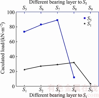
Figure 11 Calculated bearing load from S1 to S8
In accordance with the same method, the load on the rock strata above the stratum is calculated. It can be seen that the  and
and  strata affect the load carried by the stratum, while there is no influence of the
  stratum on the load borne by the stratum. Hence, the load borne by the coal seam is (q7)5 and (q8)5<(q7)5, which satisfies the loading condition for the separation between the stratum and the stratum of the roof.
Step 2: Determining deflection
Owing to the fart that the load borne by the stratum is (q4)1, the deflection equation of the stratum can be acquired by substituting it into Eq. (23), namely:
 (28)
(28)
Through Eq. (24), when x=lm/2, the maximum subsidence of the stratum w(x)max1 is:
 (29)
(29)
Then from Eq. (23), the deflection curve of the stratum is:
 (30)
(30)
Moreover, Eq. (24) shows that the maximum subsidence of the stratum w(x)max2 is:
 (31)
(31)
Owing to 
 the maximum clearance between them is:

 (32)
(32)
The stratum is made up of fine sandstones, which are characterized by great thickness and strength, so it is regarded as the key stratum of the roadway roof. Likewise, it can be found that 
The deflection curves for the and strata, and the  and strata are shown in Figure 12. It can be seen that the interlayer deflection close to the surface of the roadway roof is much greater than that far from the surface of the roadway.
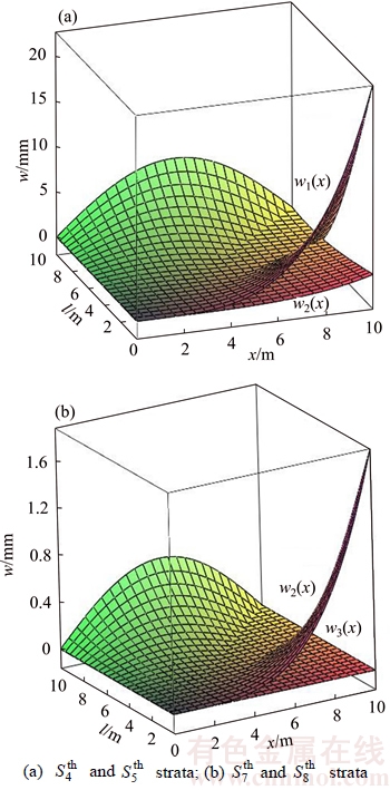
Figure 12 Deflection curves between adjacent strata in roadway roof in an extra-thick coal seam:
Thereby, both the and strata, and the and strata meet the deflection conditions for roof separation.
Step 3: Determining limiting span
According to the principle of composite beams, the deflection curves for all strata are consistent. In consequence, the deflection curves for strata S1, S2, S3 and S4 are w1(x). Through Eq. (26), it can be seen that the relationship between the maximum tensile stress and the length of the stratum is:
 (33)
(33)
From Eq. (27), the limiting span calculated from the maximum tensile stress is:

Considering the effect of the stratum on the stratum, the load borne by the stratum is:

According to Eq. (26), the relationship between the maximum tensile stress and the width of the roadway of the stratum is:
 (34)
(34)
Then through Eq. (27), the limiting span is:

The limiting spans of strata S3�CS7 can be successively computed and compared with the excavated width of the roadway in the same way, as shown in Figure 13. It can be found that the limiting spans of strata S1�CS7 are greater than the width of the roadway. As for the stratum, as the key stratum, it is obvious that the limiting span is much greater than the width of the roadway. Thus, all of them can meet the limiting span conditions required for separation.
The relationship between the maximum tensile stress on each stratum and the length of the roadway is shown in Figure 14. The maximum tensile stress on each stratum increases theoretically with increasing roadway span.
Whereas, as for the roadway with a span of 5 m, the maximum tensile stresses on all strata are less than that required for the corresponding breaking span.
Step 4: Relationship between the position of key stratum and zone of influence of roof separation
The calculated results indicate that the distance between the stratum, namely the key stratum, and the surface of the roadway roof is 11.62 m, which is much greater than the zone of influence of the separation of the roadway roof in its extra-thick coal seam, i.e., h1>h0. Therefore, combined with Figure 6, it is evident that the interlayer separation between the stratum on the stratum would not happen in field, and thus the separation should not be considered.
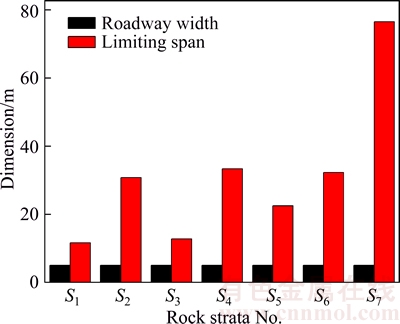
Figure 13 Limiting span for different rock strata overlying bottom-driven roadway within an extra thick coal seam
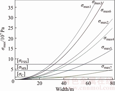
Figure 14 Theoretical relationship between maximum tensile stress and roadway width
3.3 Field monitoring results
The roof separation of a continuous region in the roadway was monitored with an on-line monitoring device. The distributed technology and intelligent integrated sensor were used in this device. The mining monitoring substation for displacement was connected with the upper main station to transmit the monitoring data to the ground monitoring server. Based on the huge amount of data from roof monitoring above the coal roadways, it was found that bedding separation often occurs in the roof of two times height of the roadway. In order to further investigate the damage and influence range of bedding separation above the coal seams and to exam the situation of bedding separation beyond the range of anchorage zone, 8 monitoring points were set up in the vertical direction from the first point 1.8 m far away from the top of the roadway to the 8th point 8.8 m in steps of 1 m, and the interval between adjacent sensors was 1.5 m, from which six groups of typical monitoring results (Figure 15) were selected.
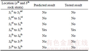
The bedding separations mainly focus on thickness of 3.8 m and 6.8 m above the roof. Due to the micro-differences in the thickness of the occurrence of the field coal-rock, the roof interlayer separations are mainly at the and strata. The separation at the thickness of 6.8 m mainly lies in the thick coal seam, which is associated with the separation produced by the extension of joint fissures in the coal seam. By comparing the predicted value and field monitoring, the results for the upper limiting position of the separation between the roof coal seams and rock strata are shown in Table 2. It was found that the upper limiting position of the roof interlayer separation obtained using the two different methods is consistent, which proved the validity of the theoretical method.
4 Conclusions
1) A mechanical model for the interlayer separation overlying a bottom-driven roadway within an extra-thick coal seam was established to deduce the vertical stress and the length of the lateral plastic and elastic zones in roadway roof strata, as well as the deflection equations for different areas.
2) A set of methods were used for determining the upper limiting position of the interlayer separation of the bottom-driven roadway roof within an extra-thick coal seam. Besides, combined with the mechanical calculation method, the conditions required for locating the upper limiting position of the interlayer separation were determined, including the loading condition, limiting span, deflection condition, and a method for judging the position of the key roof stratum and the zone of influence of the separation.
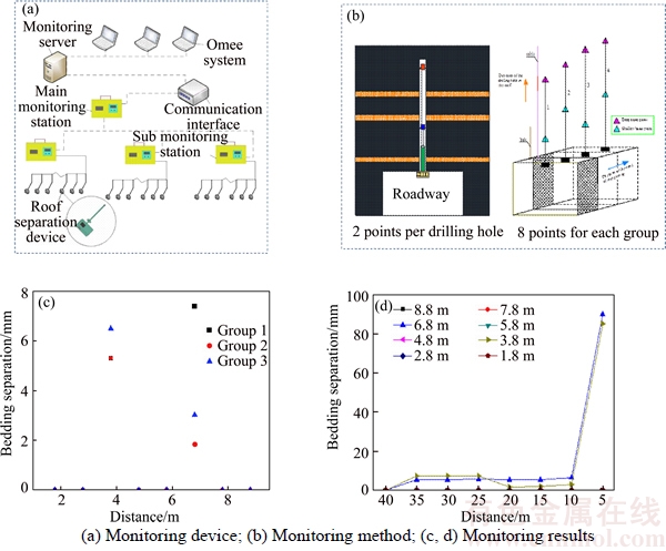
Figure 15 Monitoring results for roof separation at a measuring point in roadway of an extra-thick coal seam:
Table 2 Comparison between predicted and monitored results for upper limiting position of interlayer separation overlying a bottom-driven roadway within an extra-thick coal seam
3) A typical bottom-driven roadway within an extra-thick coal seam was selected for the analysis and the field monitoring of its upper limiting value of interlayer separation. The computed and monitoring results demonstrated that the upper limiting position of separation determined using the two methods is consistent, which verified the validity of the proposed method.
References
[1] UNAL E, OZKAN I, CAKMAKCI G. Modeling the behaviour of longwall coal mine gate roadways subjected to dynamic loading [J]. International Journal of Rock Mechanics and Mining Sciences, 2001, 38(2): 181�C197.
[2] GONG Feng-qiang, LI Xi-bing, GAO Ke. Catastrophe progression method for stability classification of underground engineering surrounding rock [J]. Journal of Central South University: Science and Technology, 2008, 39(5): 1081�C1087. (in Chinese)
[3] LIU Hong-tao. Research on the design method of parameters supporting with bolt in coal road on the base of the anchored-clustered structure [D]. Beijing: China University of Mining and Technology (Beijing), 2007. (in Chinese)
[4] JIANG Li-shuai, SAINOKI A, MITRI H S, MA Nian-jie, HAO Zhen. Influence of fracture-induced weakening on coal mine gateroad stability [J]. International Journal of Rock Mechanics and Mining Sciences, 2016, 88: 307�C317.
[5] ZHANG Yuan, WAN Zhi-jun, GU Bin, ZHOU Chang-bing. An experimental investigation of transient heat transfer in surrounding rock mass of high geothermal roadway [J]. Thermal Science, 2016, 20(6): 2115�C2124.
[6] KUSHWAHA A, SINGH SK, TEWARI S, SINHA A. Empirical approach for designing of support system in mechanized coal pillar mining [J]. International Journal of Rock Mechanics and Mining Sciences, 2010, 47(7): 1063�C1078.
[7] PALEI S K, DAS S K. Sensitivity analysis of support safety factor for predicting the effects of contributing parameters on roof falls in underground coal mines [J]. International Journal of Coal Geology, 2008, 75(4): 241�C247.
[8] XIE He-ping, WANG Jin-hua, SHEN Bao-hong, LIU Jian-zhong, JIANG Peng-fei, ZHOU Hong-wei, LIU Hong, WU Gang. New idea of coal mining: Scientific mining and sustainable mining capacity [J]. Journal of China Coal Society, 2012, 37(7): 1069�C1079.
[9] YAN Hong. Roof coal deformation mechanism and its control technology for roadways driving along the floor in ultra-thick coal seams [M]. Xuzhou: China University of Mining and Technology Press, 2017. (in Chinese)
[10] KUMARA R, SINGHA A K, MISHRAB A K, SINGHA R. Underground mining of thick coal seams [J]. International Journal of Mining Science and Technology, 2015, 25(6): 885�C896.
[11] WANG Qi. Research on control mechanism of surrounding rock failure in deep roadways with thick top-coal and contrast of new support systems [D]. Jinan: Shandong University, 2012. (in Chinese)
[12] LI S C, WANG Q, WANG H T, JIANG B, WANG D C, ZHANG B, LI Y, RUAN G Q. Model test study on surrounding rock deformation and failure mechanisms of deep roadways with thick top coal [J]. Tunnelling and Underground Space Technology, 2015, 47: 52�C63��
[13] HEBBLEWHITE B K, LU T. Geomechanical behavior of laminated, weak coal mine roof strata and the implications for a ground reinforcement strategy [J]. International Journal of Rock Mechanics and Mining Sciences, 2004, 41(1): 147�C157.
[14] LU Ting-kai, LIU Yu-zhou, YU Hai-yong. Separation characteristics and mechanisms of laminated composite roof strata of longwall roadway [J]. Chinese Journal of Rock Mechanics and Engineering, 2005, 24(s1): 4663�C4669��(in Chinese)
[15] SHEN Bao-tang, POULSEN B. Investigation of overburden behaviour for grout injection to control mine subsidence [J]. International Journal of Mining Science and Technology, 2014, 24(3): 317�C323.
[16] ZHANG Nong, YUAN Liang. Control principle of separating and broken roof rock strata in roadway [J]. Journal of Mining & Safety Engineering, 2006, 23(1): 34�C38. (in Chinese)
[17] SHEN Rong-xi, LIU Chang-you, WU Xiu-yi. Analysis and calculation on roof separation critical values of solid-coal roadway and gob-side roadway supported with bolts [J]. Journal of Sichuan University: Engineering Science Edition, 2007, 39(3): 19�C23. (in Chinese)
[18] GU Shuan-cheng, DING Xiao. Elastoplastic analysis of effect of bed separation on anchored mass loading in rock mass [J]. Rock and Soil Mechanics, 2013, 34(9): 2649�C2654. (in Chinese)
[19] JACOB O. The origin of roof falls in starting faces with the caving system [J]. International Journal of Rock Mechanics and Mining Sciences, 1964, 1(3): 313�C314.
[20] ZHANG Guo-hua, LIANG Bing, ZHANG Hong-wei, ZHANG Xue-feng. Analysis of the roof separation in mining roadway and technical parameters determination of bolt combined supporting [J]. Journal of Chongqing University, 2010, 33(7): 135�C140. (in Chinese)
[21] HAN Chang-liang, ZHANG Nong, LI Gui-cheng, KAN Jia-guang. Bed separation mechanism under sequential roof collapse condition in a gob-side entry retaining [J]. Journal of China University of Mining & Technology, 2012, 41(6): 893�C899. (in Chinese)
[22] YU Tao, WANG Lai-gui. Mechanism of generation of overburden separation layer [J]. Journal of Liaoning Technical University, 2006, 25(s1): 132�C134. (in Chinese)
[23] APEL D B. Using ground penetrating radar (GPR) in analyzing structural composition of mine roof [J]. Mining Engineering, 2005, 57: 56�C60.
[24] XIE Jian-lin, XU Jia-lin. Numerical and physical simulation of the detection of roof separation with ground penetrating radar [J]. Journal of Mining & Safety Engineering, 2017, 34(2): 317�C322. (in Chinese)
[25] ZHANG Bai-sheng, KANG Li-xun, YANG Shuang-suo. Numerical simulation on roof separation and deformation of full seam roadway with stratified roof and large section [J]. Journal of Mining & Safety Engineering, 2006, 23(3): 264�C267. (in Chinese)
[26] QIAN Ping-gao, XIE He-ping. Stability analysis of the damage rock strata within the roof and floor of the roadway [J]. Jiangsu Coal, 1992, 12(3): 12�C15. (in Chinese)
[27] WU De-yi, WEN Guang-kun, WANG Ai-lan. Discrimination of stability between layers of compound roof in deep mining [J]. Journal of Mining & Safety Engineering, 2011, 28(2): 252�C257. (in Chinese)
[28] KWON S, WILSON J W. Deformation mechanism of the underground excavations at the WIPP site [J]. Rock Mechanics and Rock Engineering, 1999, 32(2): 101�C122.
[29] QIAN Ming-gao, MIAO Xie-xing, XU Jia-lin. Key strata theory in ground control [M]. Xuzhou: China University of Mining and Technology Press, 2003. (in Chinese)
(Edited by YANG Hua)
���ĵ���
�غ�ú���ص�����������������λ�õ��ж�����
ժҪ��������������Χ��ʧ���ƻ���ú����ð���ֱ��¹ʵ���Ҫ����֮һ�������Զ���ú���к���������غ�ú���ص������Ϊͻ��������չ������������ȶ��Կ��ƽ�����ֹð���¹���Ҫǰ���Ǻ���ȷ����������������λ�á��������غ�ú���ص����Ϊ�о�������Զ�������������λ�ú���ȷ�����⣬�ۺ�������ѧ���㡢���۷������ֳ����ȷ������������غ�ú����������������ѧģ�ͣ������Ƶ��ó�����������Ҳ�����������͵������Ĵ�ֱӦ�������ȼ���ͬ�����Ӷȷ���ʽ�������һ���ж��غ�ú������������������λ�õķ������������ѧ��ѧ���㷽���Ƶ��ó�����������λ��ȷ������Ҫ����ĺ�������������ȡ��Ӷ�����������ؼ���λ�������λ�÷�Χ���ж�ʽ��ѡ������غ�ú��������в���������ֵ�����۷������ֳ���⣬�����Ƶ������ݼ������ʾ����ȷ�����������λ����һ�µģ�֤����������ж���������ȷ�ġ�
�ؼ��ʣ��غ�ú�㣻������㣻ú�ð������ѧģ��
Foundation item: Project(2017XKQY012) supported by the Fundamental Research Funds for the Central Universities, China; Project(PAPD) supported by the Priority Academic Program Development of Jiangsu Higher Education Institutions, China
Received date: 2016-12-12; Accepted date: 2017-12-10
Corresponding author: YAN Hong, PhD, Associate Professor; Tel: +86�C516�C83593019; E-mail: linodex@163.com: ORCID: 0000- 0001-6784-5962

