Comprehensive safety factor of roof in goaf underdeep high stress
��Դ�ڿ������ϴ�ѧѧ��(Ӣ�İ�)2021���2��
�������ߣ������� ������ ���� �����
����ҳ�룺595 - 603
Key words��deep mining; high stress; hingeless arch; comprehensive safety factor; stope span
Abstract: The safety factor of roof under deep high stress is a quantitative index for evaluating roof stability. Based on the failure mode of surrounding rock of stope roof, the mechanics model of goaf roof is constructed, and the internal force of roof is deduced by the theory of hingeless arch. The calculation method of roof safety factor (K) under the environment of deep mining is proposed in view of compression failure and shear failure of roof. The calculation formulas of shear safety factor (K1), compression safety factor (K2) and comprehensive safety factor (K) of roof are given. The influence of stope span and roof thickness on roof stability is considered in this paper. The results show that when the roof thickness remains constant, the roof safety factor decreases with the increasing of the stope span; when the stope span remains constant, the roof safety factor increases with the increasing of the roof thickness. The deep mining example shows that when the stope span is 30 m and the roof thickness is 10 m, the roof comprehensive safety factor is 1.12, which indicates the roof is in a stable state.
Cite this article as: JIANG Li-chun, JIAO Hua-zhe, WANG Yu-dan, WANG Ge-ge. Comprehensive safety factor of roof in goaf underdeep high stress [J]. Journal of Central South University, 2021, 28(2): 595-603. DOI: https://doi.org/10.1007/s11771-021-4624-y.

J. Cent. South Univ. (2021) 28: 595-603
DOI: https://doi.org/10.1007/s11771-021-4624-y

JIANG Li-chun(������)1, 2, JIAO Hua-zhe(������)3, WANG Yu-dan(����)2, WANG Ge-ge(�����)2
1. School of Civil Engineering and Transportation, South China University of Technology,Guangzhou 510640, China;
2. Institute of Safety Science and Engineering, South China University of Technology,Guangzhou 510640, China;
3. School of Civil Engineering, Henan Polytechnic University, Jiaozuo 454000, China
 Central South University Press and Springer-Verlag GmbH Germany, part of Springer Nature 2021
Abstract: The safety factor of roof under deep high stress is a quantitative index for evaluating roof stability. Based on the failure mode of surrounding rock of stope roof, the mechanics model of goaf roof is constructed, and the internal force of roof is deduced by the theory of hingeless arch. The calculation method of roof safety factor (K) under the environment of deep mining is proposed in view of compression failure and shear failure of roof. The calculation formulas of shear safety factor (K1), compression safety factor (K2) and comprehensive safety factor (K) of roof are given. The influence of stope span and roof thickness on roof stability is considered in this paper. The results show that when the roof thickness remains constant, the roof safety factor decreases with the increasing of the stope span; when the stope span remains constant, the roof safety factor increases with the increasing of the roof thickness. The deep mining example shows that when the stope span is 30 m and the roof thickness is 10 m, the roof comprehensive safety factor is 1.12, which indicates the roof is in a stable state.
Key words: deep mining; high stress; hingeless arch; comprehensive safety factor; stope span
Cite this article as: JIANG Li-chun, JIAO Hua-zhe, WANG Yu-dan, WANG Ge-ge. Comprehensive safety factor of roof in goaf underdeep high stress [J]. Journal of Central South University, 2021, 28(2): 595-603. DOI: https://doi.org/10.1007/s11771-021-4624-y.
1 Introduction
In deep mining, the goaf roof is not only affected by the load of overlying rock, but also subjected to high stress. When the external load exceeds the ultimate bearing strength of the roof, the goaf roof is prone toarch collapse and bending fracture, which induces the collapse of the stope [1-7]. Arch effect of rock mass is a self-adjusting mechanical phenomenon and the stress transmission of internal stress in rock mass can resist in homogeneous deformation [8, 9]. Taking full advantages of self-bearing capacity of the arch effect in rock mass, the stability of the goaf roof in deep mining can be improved.
It is an important way to evaluate roof stability to obtain roof safety factor by constructing goaf roof mechanics model. Some scholars have carried out related research in this field. SWIFT et al [10] made the semi-quantitative analysis to analyze the stability of goaf roof by using ratio method of roof thickness and roof span. YANG et al [11] used limit analysis and numerical simulation to explore the relationship between the stability of the roof and its thickness under additional load. LIU et al [12] studied the critical thickness of safety of roof under uniform load and concentrated load based on thin plate theory. ZHAO et al [13] used the strength reduction method of catastrophe theory to analyze the stability of overlapping goaf, and pointed out that the goaf roof had different displacement under different reduction coefficient, and judged whether the roof had been destroyed by the safety factor. XU et al [14] established a mechanical stability model of roof structure to analyze the instability mechanism of roof by applying the cusp catastrophe theory and deduced the expression of the limit thickness of goaf roof under filling body.
Overall, these studies provide an important insight into the single overlying rock load when analyzing roof safety factor, and put forward that the safety factor is mainly shear safety factor or compression safety factor. However, such studies show weak focus on the comprehensive safety factor of roof under deep high stress. This paper mainly studies the variation law of comprehensive safety factor in different sizes of roof under deep high stress and evaluates roof safety. The results reliability is verified by engineering examples and field displacement monitoring, which provides theoretical support for the stability of goaf roof under high stress in deep mining.
2 Roof mechanics model
2.1 Action form of high stress
Deep high stress is prone to bring danger to stope layout, and easily causes roof caving and floor cracking [15-18]. The failure mode of roof is closely related to stress magnitude, lithology and rock mass structure. According to Ref. [19], considering the synergistic effect of the dead weight of rock mass and tectonic stress, the high stress in the upper part of stope is simplified as concentrated force acting on the arch roof to facilitate calculation, as shown in Figure 1.
2.2 Action form of overlying rock
The distribution of overlying rock load on the roof can be regarded as a linear uniform distribution [20-24]. The magnitude of overlying rock load is related to the thickness of overlying rock, room width and stope span. The calculation formula of overlying rock load is shown as follows:
 (1)
(1)
where ��0 is the bulk density of ore body; z is the overlying rock thickness; a is the room width; l is the stope span.
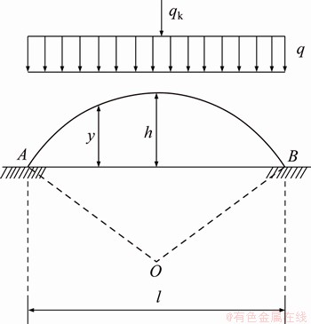
Figure 1 Hingeless arch structure model
2.3 Failure mode of roof under high stress
With the development of deep mining, the goaf roof will be displaced and bent downward under the action of high stress and overlying rock load. The failure modes of roof are compression failure and shear failure. When the compressive stress inside the roof exceeds the compressive strength limit of the roof, the roof cracks and breaks, and the compressive failure mainly occurs at this time. When the maximum shear stress exceeds the shear strength limit of the roof, shear failure occurs on the roof.
Therefore, based on the comprehensive consideration of roof compression failure and shear failure in deep mining, a comprehensive safety factor K is proposed to analyze and evaluate the safety of goaf roof.
2.4 Analysis of roof mechanics model
In the process of deep mining of metal mine, there is a great difference between the stress state of rock mass and shallow surface. The tangential stress of the surrounding rock is concentrated and the radial stress decreases. A circumferential principal compressive stress zone is produced near the top arch of the goaf. The stress load is mainly transmitted from the top arch to the foot and the surrounding rocks on both sides of the goaf through the action are similar to the arch structure. Therefore, the arched roof, intermediate columns and surrounding rock of the stope goaf can be simplified to a hingeless arch, as shown in Figure 1. After the excavation of the adjacent ore blocks, the vertical direction of the goaf roof is affected by the gravity of rock mass q and high stress qk.
The model of hingeless arch structure is solved by force method. It is a cubic statically indeterminate structure, which has three redundant constraints. The symmetrical arched roof is analyzed by using the symmetry principle of the structure. Cutting off the model at the center of the roof, the bending moment X1, axial force X2 and shear force X3 of the archtop are taken as extra unknown forces, as shown in Figure 2. The formula of force method is given in Eq.(2).
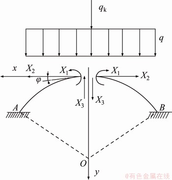
Figure 2 Basic structure of hingeless arch structure
 (2)
(2)
Using the superposition method, the bending moment M of the arbitrary section of the roof model can be obtained as follows:
 (3)
(3)
where ��ij (i=1, 2, 3; j=1, 2, 3) is the flexibility coefficient, which is the displacement along Xi direction produced by the unit force Xj acting on the basic structure alone; ��ip is the displacement along the Xi direction produced by the load acting on the basic structure alone; Xi is the stress of original structure at section i; Mi is the bending moment of any section produced by the stress Xi=1 acting on the original structure alone; Mp is the bending moment produced by the dead weight of overlying rock mass and roof and high stress acting on curved beams, (take an arch ring with wide of 1 m as the calculation unit).
By integral method, the coefficients and free terms in the force method equation (Eq. (2)) can be obtained, and the unknown superfluous forces X1, X2, X3 can be written as:

 (4)
(4)
 (5)
(5)
 (6)
(6)
where y is the ordinate of arbitrary section of arch roof; �� is the angle between the tangent of any point on the curved beam and the x axis; E is the elastic modulus of rock mass; A is the section area of the arch roof; I is the moment of inertia of arch roof section.
Under the action of high stress and the gravity of rock mass, the upper part of roof rock mass is subjected to compressive stress and the lower part is subjected to tensile stress. The uniaxial compressive strength of rock mass is far greater than its tensile strength, so the deformation of roof is mainly caused by tensile failure. According to the structural mechanics, the M(x) and the shear force Fs can be obtained by substituting Eqs. (4) and (5) into Eq. (2):
 (7)
(7)
 (8)
(8)
where x is the abscissa of arbitrary section of arch roof; y is the ordinate of arbitrary section of arch roof; r0 is the radius of hingeless arch; d is the roof thickness.
Under the action of high stress, the bending moment distribution of the arch roof is similar to the bending moment distribution form of the clamped beam at both ends. The stress concentration occurs in the roofcenter, and the maximum bending moment Mmax appears in the central area of the roof rock. The extreme value, Mmax, of M(x) can be presented as:
 (9)
(9)
where q is the dead weight stress of overlying rock; qk is the standard value of high stress load, and generally the value is 10 kN/m2; l is the stope span.
Under the action of high stress, the stress concentration occurs in the roof of the stope. With the increasing of the stope span, the stress of the roof tends to concentrate; the compressive stress of the upper strata of the roof (unhinged arch structure) increases; the tensile stress of the lower strata increases gradually; the distribution range of tensile stress expands gradually; and the tensile shear range of the roof strata of the goaf expands. As can be seen from Eq. (9), when there is only concentrated stress or horizontal stress, this assumption is still true.
3 Comprehensive safety factor of roof under deep high stress
From the foregoing analysis, the main factors affecting the stability of pillars include load, roof thickness, stope span, size of room and pillar and strength of ore body. The calculation formulas of pillar compression safety factor (K1), shear safety factor (K2) and comprehensive safety factor (K) are deduced and analyzed.
The failure forms of ore pillars mainly include brittle fracture, ductile failure and weak plane shear failure. Rock failure cannot produce obvious deformation as brittle failure for failure produces obvious plastic deformation and cannot show obvious failure surface as plastic failure. Under the combined action of overlying rock, blasting vibration and collapse body extrusion, the force of the pillar is mainly tensile stress, compressive stress and shear force. The failure form is mainly compression failure and shear failure. When the maximum compressive stress in the vertical direction exceeds the allowable ultimate compressive strength of the pillar, the pillar will have brittle failure. When the maximum shear stress exceeds the allowable ultimate shear strength of the pillar, the pillar will have plastic failure.
Therefore, based on the comprehensive consideration of the influence of compression failure and shear failure on the pillar, the comprehensive safety factor K is proposed, and the safety of the pillar is analyzed and evaluated, and the influence of deep high stress is considered. The influence of compression safety factor and shear safety factor on roof cannot be analyzed separately, so the comprehensive safety factor is proposed.
3.1 Compression safety factor
The safety factor of roof compression is the ratio of roof compressive strength to the maximum compressive stress. Under the action of overlying rock and high stress, the most unstable section of arch roof is in the center of curved beam. The axial force and the shear force of arch roof have little effect on the roof, which is usually ignored.
Based on the bending material mechanics theory, the maximum bending moment, Mmax, of the mid span section of the roof can be represented as:
 (10)
(10)
where b is the thickness of arch ring; l is the roof span; ��max is the maximum normal stress during the bending of the mid span section of the roof.
According to the rock strength theory, plastic failure occurs when the maximum tensile stress of the roof exceeds the tensile stress threshold, [��]t. ��max must be satisfied as:
 (11)
(11)
where Kv is the integrity coefficient of rock mass; ��t is the ultimate tensile strength of rock; K1 is the compression safety factor.
The compression safety factor of roof can be calculated from Eqs. (9), (10) and (11):
 (12)
(12)
where K1 is the compression safety factor of roof; d is the roof thickness; ��t is the uniaxial compressive strength.
3.2 Shear safety factor
The shear safety factor of roof is the ratio of shear strength to the maximum shear stress. According to the Mohr-Coulomb strength criterion, the shear strength of the pillar (��f) on the sliding shear plane can be obtained.
Under the action of overlying rock stress and high stress, the arch roof with a certain thickness is an equal section curved beam. The shear stress at each point equal to the distance from the neutral axis is equal on the roof shear plane. At each point on the neutral axis, the shear stress reaches the maximum value ��max:
 (13)
(13)
where Fs is the shear force of roof section; Iz is the moment of inertia for the cross section of the roof to the sexual axis on semicircle, Iz=2r0d; is the static moment of the part area with a distance greater than y from the neutral axis on the cross section of the roof to the neutral axis on semicircle, =��r03d.
In order to ensure the pillar safety, the shear strength of the roof should be greater than the ultimate shear strength, which is ��f>��max. The pillar shear safety factor (K2) can be obtained as:
 (14)
(14)
where ��max is the shear stress on the shear plane; ��fis the shear strength on the shear plane; c is the cohesion of rock body.
3.3 Comprehensive safety factor
The comprehensive safety factor is the ratio of the ultimate stress to the maximum compressive stress of the roof, which is a quantitative evaluation index of roof stability. Considering the failure mode of roof, the comprehensive safety factor (K) is the smaller value between compression safety factor and shear safety factor, and it can be calculated as:
 (15)
(15)
where ��cr is the limit stress of roof; �� is the maximum compressive stress in the vertical direction of roof.
When K=K1, compression failure occurs on the roof. When K=K2, shear failure occurs on the roof. When K is between K1 and K2, shear failure and compression failure will occur simultaneously on the roof.
The failure forms of ore pillars mainly include brittle fracture, ductile failure and weak plane shear failure. Rock failure does not produce obvious deformation as brittle failure. The failure produces obvious plastic deformation and does not show obvious failure surface as plastic failure.
Under the combined action of overlying rock, blasting vibration and collapse body extrusion, the force of the pillar is mainly tensile stress, compressive stress and shear force, and the failure form is mainly compression failure and shear failure. When the maximum compressive stress in the vertical direction exceeds the allowable ultimate compressive strength of the pillar, the pillar will have brittle failure. When the maximum shear stress exceeds the allowable ultimate shear strength of the pillar, the pillar will have plastic failure.
The comprehensive safety factor is the ratio of the ultimate stress to the maximum compressive stress of the pillar, and it is the quantitative evaluation index of the stability of the pillar. The failure form of pillar is comprehensively considered, and the comprehensive safety factor (K) is the smaller one.
4 Case study
4.1 Engineering survey
A copper mine with a mining depth of 1237 m is an ultra-deep mine with high stress. The main mining method is the delayed filling open stope with a production capacity of 3��106 t/a. The ore body is a kind of layer-controlled skarn copper deposit. The ore body is located in the axis of Qingshan anticline and occurs in the strata of Huanglong Formation and Chuanshan Formation of Carboniferous System, China, which is like a kind of layered ore body.
The roof is marble, and the floor is mainly siltstone and quartz diorite. Some physical and mechanical parameters of rock mass are shown in Table 1.
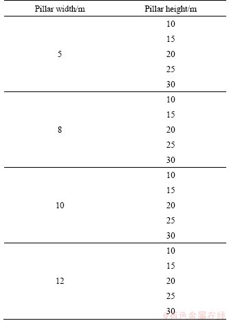
According to the actual situation of the mine, 20 groups of goaf roofs with different roof thickness (d) and stope span (l) are selected (other conditions remain unchanged). The stope spans are 10, 15, 20, 25 and 30 m, respectively, and the corresponding roof thicknesses are 5, 8, 10 and 12 m, respectively (Table 1). According to the actual situation of mines and field experiments, some physical and mechanical parameters of rock mass are listed in Table 2.
Table 1 Pillar dimension
4.2 Result analysis
4.2.1 Relationship between roof safety factor and stope span
The relationship between roof safety factor and stope span can be obtained by Eqs. (12) and (14). The trend of roof safety factor along with the change of stope span under high stress is shown in Figure 3. As shown in Figure 3, the K1 and K2 are negatively correlated with stope span, and the slope of K2 is greater than K1. As shown in Figures 3(a)-(c), K2>K1, K=K1. From Figure 3(d), when the stope span is 25 m, K=K1, the failure mode of roof is compression failure. When the stope span is greater than 25 m, K=K2, the failure mode of roof is shear failure.
4.2.2 Relationship between roof safety factor and roof thickness
When the stope span is constant, the trend of roof safety factor under the change of roof thickness is shown in Figure 4. As shown in Figure 4, when the stope span is fixed, there is a positive correlation between K1 and K2 with roof thickness, but the fluctuation amplitude is small. When the roof thickness is less than 10 m, and K=K1, the failure mode of roof is compression failure. When the roof thickness is greater than 10 m, and K=K2, the failure mode of roof is shear failure.
4.3 Engineering verification
In order to observe the change of roof displacement, the roof settlement displacement of two goafs after mining is monitored. The observation points are located in the central area of roof of two goafs respectively. Displacement monitoring for 150 d shows that the maximum displacement deformation of the roof is less than 6 mm (Figure 5), and no local collapse occurs (Figure 6). The arch effect is obvious, which confirms the reliability of theoretical analysis.
5 Conclusions
1) Considering the failure mode of stope roof surrounding rock, a mechanical model of roof hingeless arch in deep goaf is constructed, and the function expression of roof stress is given.
2) Based on the analysis of roof compression and shear failure modes in deep mining, the calculation formulas of roof compression safety factor (K1), shear safety factor (K2) and comprehensive safety factor (K) are put forward. The influence of stope span and roof thickness on roof stability is studied.
3) Taking a large gold mine as an example, the variation characteristics of three safety factors under different roof thickness and stope span are analyzed. The results show that when the roof thickness is fixed, the roof safety factor decreases with the increasing of stope span. When the stope span is fixed, the roof safety factor increases with the increasing of roof thickness. The reliability of roof safety factor is verified by engineering examples.
Table 2 Rock physical and mechanics parameters
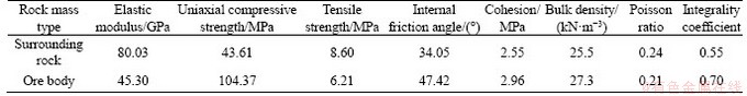
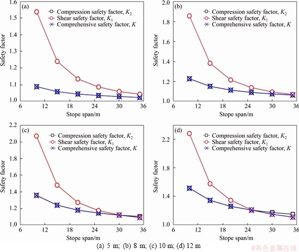
Figure 3 Roof safety factor of different stope span and different roof thickness under high stress:
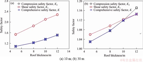
Figure 4 Roof safety factor of different thickness and different stope span under high stress:
Contributors
JIANG Li-chun provided the concept and edited the draft of manuscript. JIAO Hua-zhe established the models and wrote the first draft of the manuscript. WANG Yu-dan conducted the literature review and analyzed the calculated results. WANG Ge-ge edited the draft of manuscript. All authors replied to reviewers�� comments and revised the final version.
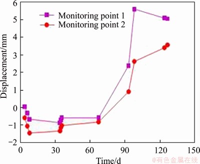
Figure 5 Displacement monitoring curves of goaf
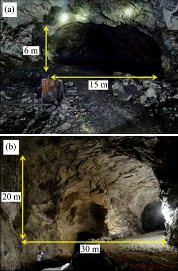
Figure 6 Realistic picture of stope roof (a, b) at the end of mining
Conflict of interest
JIANG Li-chun, JIAO Hua-zhe, WANG Yu-dan, and WANG Ge-ge declare that they have no conflict of interest.
References
[1] SUN Jian, HU Yang, ZHAO Guang-ming. Relationship between water inrush from coal seam floors and main roof weighting [J]. International Journal of Mining Science and Technology, 2017, 27(5): 873-881. DOI: 10.1016/j.ijmst. 2017.07.010.
[2] YAN Hong, ZHANG Ji-xiong, LI Lin-yue, FENG Min-rui, LI Tian-tong. Prediction of upper limit position of bedding separation overlying a coal roadway within an extra-thick coal seam [J]. Journal of Central South University, 2018, 25(2): 448-460. DOI: 10.1007/s11771-018-3749-0.
[3] HU Jian-hua, LEI Tao, ZHOU Ke-ping, LUO Xian-wei, YANG Nian-ge. Mechanical response of roof rock mass unloading during continuous mining process in underground mine [J]. Transactions of Nonferrous Metals Society of China, 2011, 21(12): 2727-2733. DOI: 10.1016/S1003- 6326(11)61116-3.
[4] MERIEL Y, GABRIEL W, ELIZABETH H. Investigation of factors influencing roof stability at a Western U.S. longwall coal mine [J]. International Journal of Mining Science and Technology, 2019, 29(1): 139-143. DOI: 10.1016/j.ijmst. 2018.11.019.
[5] HAN Chang-liang, ZHANG Nong, RAN Zhi, GAO Rui, YANG Hou-qiang. Superposed disturbance mechanism of sequential overlying strata collapse for gob-side entry retaining and corresponding control strategies [J]. Journal of Central South University, 2018, 25(9): 2258-2271. DOI: 10.1007/s11771-018-3911-8.
[6] CHEN Xin-ming, JIN Xiang-fei, JIAO Hua-zhe, YANG Yi-xuan, LIU Juan-hong. Pore connectivity and dewatering mechanism of tailings bed in raking deep-cone thickener process [J]. Minerals, 2020, 10(4): 375-397. DOI: 10.3390/min 10040375.
[7] YANG Yi-xuan, ZHAO Tong-qian, JIAO Hua-zhe, WANG Yun-fei, LI Hai-yan. Potential effect of porosity evolution of cemented paste backfill on selective solidification of heavy metal ions [J]. International Journal of Environmental Research and Public Health, 2020, 17(3): 814-830. DOI: 10.3390/ijerph17030814.
[8] WANG Qi, LUAN Ying-cheng, JIANG Bei, LI Shu-cai, YU Heng-chang. Mechanical behaviour analysis and support system field experiment of confined concrete arches [J]. Journal of Central South University, 2019, 26(4): 970-983. DOI: 10.1007/s11771-019-4064-0.
[9] WU Ai-xiang, SHEN Hui-ming, JIANG Li-chun, JIAO Hua-zhe, WANG Yi-ming. Arching effect of long-narrow cemented paste backfill body and its effect on target strength [J]. The Chinese Journal of Nonferrous Metals, 2016, 26(3): 648-654. DOI: 10.19476/j.ysxb.1004.0609.2016.03.021. (in Chinese)
[10] SWIFT G M, REDDISH D J. Stability problems associated with an abandoned ironstone mine [J]. Bulletin of Engineering Geology and the Environment, 2002, 61(3): 227-239. DOI: 10.1007/s10064-001-0147-9.
[11] YANG Yu-jiang, GAO Han, LI Yuan-hui. Analysis on roof stability of concealed gob area under additional loading [J]. Journal of Northeastern University (Natural Science), 2011, 32(9): 1332-1335. DOI: 10.12068/j.issn.1005-3026.2011. 09.029. (in Chinese)
[12] LIU Xiao-bo, AN Long, ZHANG Feng-peng. Analysis on roof stability of gob area based on thin plate theory [J]. Journal of Northeastern University (Natural Science), 2012, 33(11): 1628-1632. DOI: 10.12068/j.issn.1005-3026.2012. 11.027. (in Chinese)
[13] ZHAO Yan-lin, WU Qi-hong, WANG Wei-jun, WAN Wen, ZHAO Fu-jun. Strength reduction method to study stability of goaf overlapping roof based on catastrophe theory [J]. Chinese Journal of Rock Mechanics and Engineering, 2010, 29(7): 1424-1434. https://kns.cnki. net/kcms/detail/detail.aspx?dbcode=CJFD&dbname=CJFD2010&filename=YSLX201007019&v=twlOvu6SzOMyuwPZgI9SHx4xrmqMJWt%25mmd2BTiasREIVkpMfvycIFevgz2v8kvEwClZ4. (in Chinese)
[14] XU Heng, WANG Yi-ming, WU Ai-xiang, LI Fang-fang, GAO Wei-hong. A computational model of safe thickness of roof under filling body based on cusp catastrophe theory [J]. Chinese Journal of Rock Mechanics and Engineering, 2017, 36(3): 579-586. DOI: 10.13722/j.cnki.jrme.2016.0199. (in Chinese)
[15] DU Chun-hang, CAO Ping, CHEN Yu, LIU Jie, ZHAO Yan-lin, LIU Jing-shuo. Study on the stability and deformation of the roadway subjected to high in-situ stresses [J]. Geotechnical & Geological Engineering, 2017, 35(4): 1-14. DOI: 10.1007/s10706-017-0197-9.
[16] XIE Sheng-rong, PAN Hao, ZENG Jun-chao, WANG En, CHEN Dong-dong, ZHANG Tao, PENG Xue-jiao, YANG Jun-hui, CHEN Feng, QIAO Shun-xing. A case study on control technology of surrounding rock of a large section chamber under a 1200-m deep goaf in Xingdong coal mine, China [J]. Engineering Failure Analysis, 2019, 104: 112-125. DOI: 10.1016/j.engfailanal.2019.05.039.
[17] ZHANG Guang-chao, HE Fu-lian, LAI Yong-hui, JIA Hong-guo. Ground stability of underground gateroad with 1 km burial depth:A case study from Xingdong coal mine, China [J]. Journal of Central South University, 2018, 25(6): 1386-1398. DOI: 10.1007/s11771-018-3834-4.
[18] LI Shu-cai, WANG Hong-tao, WANG Qi, JIANG Bei, WANG Fu-qi, GUO Nian-bo, LIU Wen-jinag, REN Yao-xi. Failure mechanism of bolting support and high-strength bolt-grouting technology for deep and soft surrounding rock with high stress [J]. Journal of Central South University, 2016, 23(2): 440-448. DOI: 10.1007/s11771-016-3089-x.
[19] LIANG Ning, WU Fa-quan, WANG Yun-feng, BAO Han. Analysis of defornation and failure of rock mass of deep Guanshan tunnel under high in situ stress [J]. Rock and Soil Mechanics, 2016, 37(Supp.2): 330-336. DOI: 10.16285/ j.rsm.2016.S2.041. (in Chinese)
[20] ZHANG Hua-lei, TU Min, CHENG Hua, TANG Yong-zhi. Breaking mechanism and control technology of sandstone straight roof in thin bedrock stope [J]. International Journal of Mining Science and Technology, 2020, 30(2): 259-263. DOI: 10.1016/j.ijmst.2018.10.006.
[21] LIU Chuang, LI Hua-min, MITRI H, JIANG Dong-jie, LI Hui-gui, FENG Jun-fa. Voussoir beam model for lower strong roof strata movement in longwall mining-Case study [J]. Journal of Rock Mechanics and Geotechnical Engineering, 2017, 9(6): 1171-1176. DOI: 10.1016/j.jrmge. 2017.07.002.
[22] JIAO Hua-zhe, WANG Shu-fei, WU Ai-xiang, SHEN Hui-ming, WANG Jian-dong. Cementitious property of NaAlO2-activated Ge slag as cement supplement [J]. International Journal of Minerals Metallurgy and Materials, 2019, 26(12): 1594-1603. DOI: 10.1007/s12613-019- 1901-y.
[23] LIU Xi-ling, LUO Ke-bing, LI Xi-bing, LI Qi-yue, WANG Wei-hua, GONG Feng-qiang. Cap rock blast caving of cavity under open pit bench [J]. Transactions of Nonferrous Metals Society of China, 2017, 27(3): 648-655. DOI: 10.1016/ S1003-6326(17)60072-4.
[24] JIANG Li-chun, YANG Chao, JIAO Hua-zhe. Ultimately exposed roof area prediction of bauxite deposit goaf based on macro joint damage [J]. International Journal of Mining Science and Technology, 2020, 30(5): 699-704. DOI: 10.1016/j.ijmst.2020.06.005.
(Edited by ZHENG Yu-tong)
���ĵ���
���Ӧ���²ɿ��������ۺϰ�ȫϵ��
ժҪ�����Ӧ���¶��尲ȫϵ�������۶����ȶ��ԵĶ�������ָ�ꡣ���ڲɳ�����Χ���ƻ���ʽ�������˿���������ѧģ�ͣ������¹������Ƶ�����������С����Զ���ѹ���������ƻ���ʽ�����������ɻ����¶��尲ȫϵ��(K)�ļ��㷽���������������а�ȫϵ��(K1)��ѹ����ȫϵ��(K2)���ۺϰ�ȫϵ��(K)�ļ���ʽ���о��ɳ���ȡ������ȶԶ����ȶ��Ե�Ӱ�졣�����������������һ��ʱ�����尲ȫϵ�����Ųɳ���ȵ����Ӷ��ݼ������ɳ����һ��ʱ�����尲ȫϵ�����Ŷ����ȵ����Ӷ��������ÿ������ʵ���������ڲɳ����Ϊ30 m��������Ϊ10 m�������£������ۺϰ�ȫϵ��Ϊ1.12ʱ�����崦���ȶ�״̬��
�ؼ��ʣ�����ɣ���Ӧ�����¹����ۺϰ�ȫϵ�����ɳ����
Foundation item: Projects(51974135, 51704094) supported by the National Natural Science Foundation of China; Project(2016YFC0600802) supported by the National Key Research and Development Program of China; Project(2020M672226) supported by the China Postdoctoral Science Foundation
Received date: 2020-07-18; Accepted date: 2020-10-07
Corresponding author: JIAO Hua-zhe, PhD, Lecture; Tel: +86-18439113018; E-mail: jiaohuazhe@hpu.edu.cn; ORCID: https://orcid.org/ 0000-0002-4098-5073

