Trans. Nonferrous Met. Soc. China 23(2013) 392-399
Tribological behavior and mechanisms of graphite/CaF2/TiC/Ni-base alloy composite coatings
Bin CAI, Ye-fa TAN, Long HE, Hua TAN, Xiao-long WANG
College of Field Engineering, PLA University of Science and Technology, Nanjing 210007, China
Received 6 January 2012; accepted 18 May 2012
Abstract: In order to reduce the friction coefficients and improve the wear resistance of mechanical parts, which work in the severe friction and wear conditions at heavy loads, the graphite/CaF2/TiC/Ni-base alloy composite coatings were prepared by plasma spray and their tribological behavior and mechanisms were investigated. The results show that the friction coefficients of the composite coatings are in the range of 0.22-0.288, which are reduced by 25.9% to 53% compared with those of the pure Ni-base alloy coatings, and the wear rates of the former are 18.6%-70.1% less than those of the latter. When wear against GCr15 steel balls, a transferred layer mainly composed of ferric oxides, graphite and CaF2 may gradually develop on the worn surface of the composite coatings, which made the friction and wear between GCr15 steel ball and the composite coatings change into that between the former and the transferred layer. So the friction coefficients and the wear rates of the composite coatings are greatly reduced because of the solid lubrication effect of the transferred layer. The main wear mechanism of the composite coatings is delamination of the transferred layer in friction process.
Key words: plasma spray; composite coatings; Ni-base alloy; graphite; TiC; CaF2; tribology
1 Introduction
In metallurgy and mine machinery, many friction parts usually suffer from severe friction and wear under heavy load friction conditions. These parts not only have to possess the property of high wear resistance to ensure the service lives of the machinery, but also need low friction coefficients to reduce energy consumption and noise. Especially, many friction parts work in the open structure and severe friction conditions, in which they cannot be lubricated by liquid or grease. With the development of surface technology and solid lubrication, the effective method to solve this problem is to prepare surface coatings that have excellent anti-friction and anti-wear properties on the surface of machine parts by surface technology [1].
Ni-base alloy has excellent properties of anti-wear and corrosion resistance, it is widely used in surface engineering to strengthen friction parts of machinery [2,3]. However, the pure Ni-base alloy coating cannot provide enough wear resistance or small friction coefficients under the high contact stress and dry friction conditions. The wear resistance of Ni-base alloy coating can be greatly improved by reinforcing of hard phase particles. At present, Ni-base alloy coatings reinforced by hard phases are mainly prepared by electro plating, laser cladding and thermal spray [4-6]. For example, the Ni-base electro-brush plating coatings reinforced by nano-alumina grains were prepared and researched [4], which showed that the micro-hardness and fretting wear-resistance of the coatings were superior to those of the common pure Ni-base plating coatings. But the electro plating coating is usually so thin that it may easily failure under heavy load friction conditions. The wear resistance of the laser clad TiC/(NiAl-Ni3Al) composite coating on steel surface was enhanced by 9 times with the friction coefficient of about 0.4 compared with the AISI 321 steel under dry sliding conditions [5]. However, the laser clad technology usually needs the complicated and expensive equipment and is difficult to treat with large machine parts. Incorporating 2% nano-Al2O3 into the plasma spray Ni-base alloy coating may improve its wear resistance by 1 times [6]. Plasma spray is simple and low-cost, which is suitable for depositing coatings on large mechanical part surface.
On the promise of keeping wear resistance of the coatings, the friction coefficients of the particle reinforced composite coatings can be reduced by addition of solid lubricants. For instance, LIU et al [7] researched the laser clad /Al4C3/TiC/CaF2 composite coatings on the γ-TiAl intermetallic alloy, the friction coefficient of the composite coatings is reduced by 44% compared with the coating without CaF2, and the wear loss of the former is about 1/6 of that of the latter. The tribological properties of the graphite/TiC/Ni-base alloy composite coatings were studied, the results show that the friction coefficients and the wear rates of the composite coatings are both less than those of the pure Ni-base alloy coating [8]. In addition, it is referred that two or more types of solid lubricants may present better lubrication than single type [9]. At present, the researches on adding multi solid lubricants into the plasma spray particle reinforced Ni-base alloy coatings are scarce, and the anti-friction and anti-wear mechanisms of the composite coatings also need to be investigated. Graphite and CaF2 are the most commonly employed solid lubricants in anti-friction coatings, and CaF2 possesses solid lubrication properties at high temperatures [10,11]. In this work, the solid lubricants of graphite and CaF2 were incorporated with the TiC/Ni- base alloy coatings by plasma spray. The microstructure, microhardness and tribological properties of the composite coatings were investigated to provide experiment and theory foundations for the application of the composite coatings to engineering fields.
2 Experimental
2.1 Specimen preparation
The graphite/CaF2/TiC/Ni-base alloy composite materials were composed of nickel-clad graphite powders, nickel-clad CaF2 powders, TiC powders and Ni-base alloy powders. The nickel-clad graphite powders containing 75% nickel were in the particle size of 75-128 μm. The nickel-clad CaF2 powders contained 62.04% nickel and their particle size was 60-90 μm. Diameter of the TiC particles was 2 μm. The chemical compositions of the Ni-base alloy powders with the size from 55 to 128 μm were 15.5% Cr, 3% B, 4% Si, 14% Fe, 0.75% C and residue of Ni (in mass fraction). The contents of nickel-clad graphite powders, nickel-clad CaF2 powders and TiC powders were optimized using the orthogonal experiment, which are respectively 10%, 14% and 24%.
The 45 carbon steel was chosen as the substrate, which was previous treated by degrease and rust cleaning. The composite coating materials were sprayed on the surface of 45 carbon steel by plasma spray equipment of DH1080. The spray technological parameters were electric current of 600 A, voltage of 40 V and spray distance of 80 mm. The thickness of the composite coatings was 400 μm and its surface roughness was 0.3 μm after being ground by diamond wheel.
2.2 Tribological tests
The tribological tests were carried out in a ball-on-disc tribometer of HT-500. The upper specimen was a GCr15 steel ball with the diameter of 4 mm, surface roughness of 0.05 μm and micro-hardness of HV739. The down one was the composite coating. The GCr15 steel ball slid against the composite coatings under the normal load of 6, 8, 10 and 12 N at the speed of 0.1 m/s in dry sliding friction condition. The wear rate of the coating (V) was calculated by the following equation:
 (1)
(1)
where Δm is the mass loss and was measured by the balance of TG328A; ρ is the density of the coating; L is the total sliding distance.
2.3 Surface analysis
The microstructure and worn surface morphology of the composite coatings were observed by scanning electronic microscope (SEM) of QUANTA200, and the chemical composition of the worn surfaces was analyzed by energy-dispersive X-ray analysis of EDAX. The microhardness of the coating was measured using a DHV-1000 sclerometer.
3 Results and discussion
3.1 Microstructure of graphite/CaF2/TiC/Ni-base alloy composite coatings
The microstructures of the graphite/CaF2/TiC/ Ni-base alloy composite coatings and their EDX spectra are shown in Fig. 1. It shows that the microstructure of the composite coating is compact with few holes as shown in Fig. 1(a). The grey structure in the coating is Ni-base alloy matrix. The dark grey structure marked by arrow A, which distributed uniformly in the coating, is composed of 15.31%C, 0.51%Si, 66.18%Ti, 1.09%Cr and 16.92%Ni. It suggests that the dark grey structure is mainly TiC. The chemical composition of the bright white region marked by arrow B is 6.76%C, 3.88% F, 0.69%Si, 10.67%Ca, 19.21%Ti, 2.27%Cr, 1.55%Fe and 54.97%Ni. It can be inferred that CaF2 and TiC assemble in the bright white region. There is also black region that contains 100% C as marked by arrow C in the coating, which is graphite. TiC in the composite coatings may reinforce the Ni-base alloy and improve wear resistance of the coating. Graphite and CaF2 can be sprayed into the matrix of Ni-base alloy after clad-treating of nickel and take the solid lubrication effect to reduce friction coefficient.
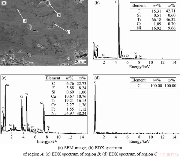
Fig. 1 Morphology of graphite/CaF2/TiC/Ni-base alloy composite coatings and its EDX spectra
The microhardness of the composite coatings as a function of distance to the surface is shown in Fig. 2. It is found that the microhardness changes in the range of HV 425.4-662.5 with the increase of distance and the average value is HV 550.3. The microhardness decreases to HV 438.2 and HV 425.4 at the distance of 240 μm and 360 μm, respectively. Because the solid lubricants such as graphite and CaF2 are so soft that they may easily deform under the press action of the sclerometer which leads to the increase of the plastic deformation of the composite coatings. It may account for the decrease of microhardness.
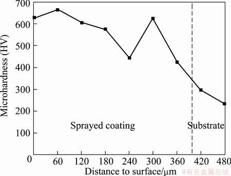
Fig. 2 Microhardness of composite coatings as function of distance to surface
3.2 Friction and wear behavior of graphite/ CaF2/TiC/Ni-base alloy composite coatings
The friction coefficients of the graphite/CaF2/ TiC/Ni-base alloy composite coatings and the pure Ni-base alloy coating with the change of loads are shown in Fig. 3. It can be seen that the friction coefficients of the composite coatings take on an increasing trend in the range of 0.22-0.288, which are reduced by 25.9%-53% compared with those of the pure Ni-base alloy coating.
Figure 4 shows the wear rates of the composite coatings and the pure Ni-base alloy coating as a function of loads. At the load of 6 N, the wear rate of the composite coatings is 0.23×10⁻³ mm3/m. When the loads exceed 8 N, the wear rates vary from 0.32×10⁻³ mm3/m to 0.37×10⁻³ mm3/m. It can be found that the wear rates of the composite coatings are 18.6%-70.1% less than those of the pure Ni-base alloy coatings. Especially, the composite coatings exhibit an excellent wear resistance at heavy loads.
The worn surface morphologies of the graphite/ CaF2/TiC/Ni-base alloy composite coatings at various loads are shown in Fig. 5. It can be seen that the worn surface of the coating is covered by a black dense transferred layer. Furthermore, the covered scope of the transferred layer is small at 6 N as shown in Fig. 5(a). As the load increases to 8 N, the transferred layer becomes large (Fig. 5(b)). In Fig. 5(c), the transferred layer almost completely covers the worn surface at the load of 10 N. The delamination phenomenon in the transferred layer emerges at the load of 12 N (Fig. 5(d)).
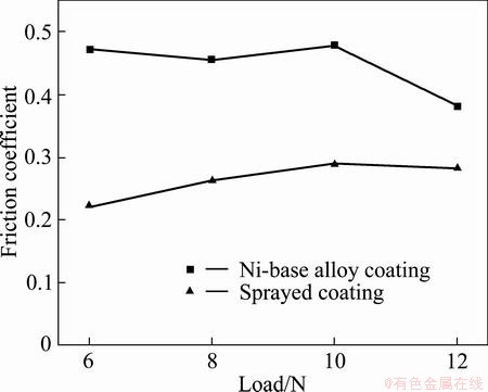
Fig. 3 Friction coefficients of composite coatings as function of loads
The EDX spectrum of the transferred layer is shown in Fig. 6. The layer is composed of 2.86% C, 29.52% O, 2.07% F, 0.33% Si, 1.64% Ca, 0.65% Cr, 61.59% Fe and 1.34% Ni. There are little Ni, Cr and Si that come from the Ni-base alloy in the transferred layer, while the amount of Fe and O in the layer is about 91.11%. This indicates that the transferred layer is mainly ferric oxides such as Fe2O3. The 2.86% C in the transferred layer is graphite, while the 2.07% F and 1.64% Ca suggest CaF2 in the layer. It can be concluded that besides ferric oxides, the transferred layer also has mixed with graphite and CaF2. Therefore, the transferred layer plays an effect of solid lubrication to reduce friction coefficient.
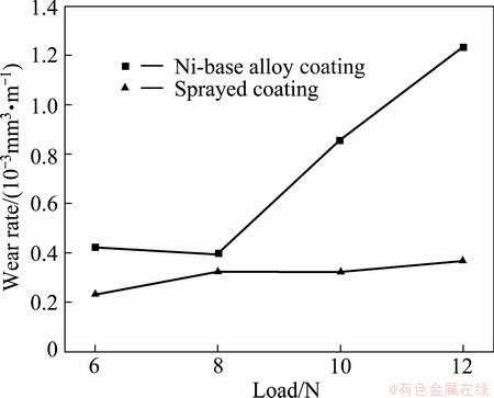
Fig. 4 Wear rates of composite coatings as function of loads
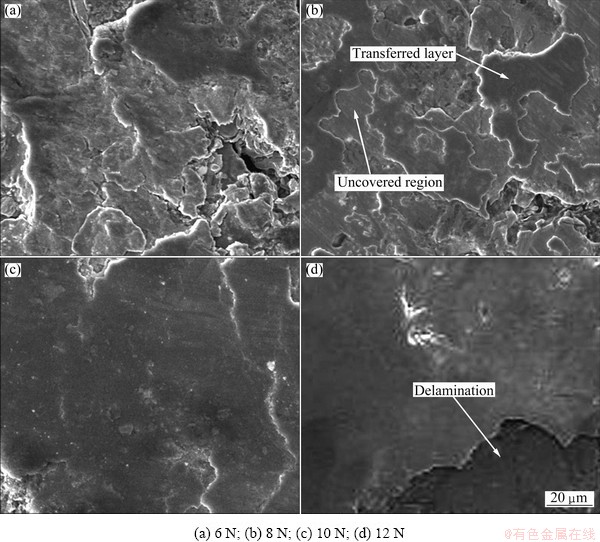
Fig. 5 Worn surfaces of composite coatings at different loads
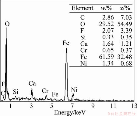
Fig. 6 EDX spectrum of transferred layer
3.3 Anti-friction mechanism of composite coatings
According to Tabor’s friction model [12], friction force (F) is composed of adhesive force (S) and plough force (P):
F=S+P (2)
At the load of 6 N, the transferred layer incompletely covers the worn surface which indicates that GCr15 steel ball contacts with both the transferred layer and the uncovered composite coating during friction. So, the normal force (W) inflicts both on the transferred layer and on the composite coating that can be expressed as follows:
W=WL+WC (3)
where WL is the normal load inflicting on the transferred layer, and WC is the normal load inflicting on the composite coating. If η is the ratio of the load on the transferred layer WL to W (0≤η≤1), WL and WC can be expressed as Eq.(4) and Eq. (5), respectively:
WL=ηW (4)
WC=(1-η)W (5)
The friction force between the GCr15 steel ball and the transferred layer is mainly the adhesive force. Equation (6) gives the adhesive force [13]:
S=Arτ (6)
where Ar is the real contact area; τ is the shear strength of the transferred layer. The real contact area between the transferred layer and the steel ball Ar1 is given by the following equation:
Ar1=WL/pr (7)
where pr is the average normal stress of the contact area. Taking the shear stress τ into consideration, pr is [14]
 (8)
(8)
where pm is the normal entirety compact plastic deformation stress, which is equal to hardness (H); α is a constant.
So,
 (9)
(9)
 (10)
(10)
where HC is the hardness of the composite coating.
The hard particles of TiC extruded on the worn surface and cut the GCr15 steel ball, so the friction force is mainly the plough force in the contact area between the composite coating and the GCr15 steel ball. The plough force may be calculated by the following formula [14]:
P=Ap (11)
where A is the plough area, p is the tensile strength of the softer material.
The micro contact model between TiC and GCr15 steel ball is presented in Fig. 7. The plough area is
A= nAi (12)
where n is the amount of TiC particles in the contact area, and Ai is the plough area of a single TiC particle shown in Fig. 7. The amount (n) of TiC particles in the contact area has a relation as follows:
 (13)
(13)
where k is the volume fraction of TiC particles, Aa is the nominal contact area between GCr15 steel ball and the coating, d is the radius of TiC particle, and VTiC is the volume of a single TiC particle.
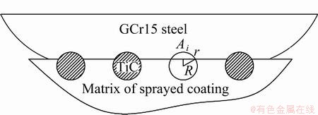
Fig. 7 Micro contact model between TiC particles and GCr15 steel
According to Fig. 7, Ai is the plough area of a single TiC particle.
 (14)
(14)
where r is the radius of the contact area between a single TiC particle and GCr15 steel, and R is the radius of TiC particle. r has a relation with the total real contact area (Ar2) between TiC particles and GCr15 steel ball as Eq. (15):
 (15)
(15)
where the Ar2 is mainly plastic contact area and can be expressed [15] as
 (16)
(16)
where HG is the hardness of GCr15 steel.
The plough force of the composite coating at 6 N may be calculated as follows: the volume fraction of TiC particles (k) is 29.5%; the diameter of TiC particle is 2 μm; Aa is supposed to be the area of the segment of the GCr15 steel ball, whose radius is 0.000684 m. So the amount of TiC particles is 207031 according to Eq. (13).
The yield strength (σs) of GCr15 steel is 518.42 MPa, so HG is 1555.25 MPa according to Eq. (17).
H=3σs (17)
The maximum value of WC is 6 N. Substituting the above data into Eq. (15), Eq. (14) and Eq. (13) respectively, then Ai is 3.05×10⁻¹⁶ m2.
The tensile strength of GCr15 steel is 742 MPa, so the plough force is 0.0469 N. It can be found that the plough force is too little to affect the friction coefficient. Therefore, the friction force of the composite coating is mainly adhesive force, and the friction coefficient (μ) can be expressed as follows:
 (18)
(18)
When the load increases to 8 N, the transferred layer becomes larger than that at 6 N, which implies that η increases, so the friction coefficient of the coating increases according to Eq. (18). As the load increases to 10 N, the transferred layer covers completely, namely η=1. The friction coefficient is
 (19)
(19)
In addition, the transferred layer also covers completely at the load of 12 N, so the friction coefficient is similar to that at 10 N.
In conclusion, the friction mechanism of the composite coatings is mainly the adhesive friction between GCr15 steel ball and the transferred layer on the composite coatings. Because the shear strength of the transferred layer composed of solid lubricants is low, the friction coefficients of the composite coatings are greatly reduced.
3.4 Generation and failure mechanisms of transferred layer
The mechanism model on generation and failure process of the transferred layer on the composite coatings in friction process is shown in Fig. 8. Figure 8(a) shows the beginning period of friction, the phases of CaF2, graphite and TiC particles distribute uniformly in the Ni-base alloy matrix, and the composite coatings have not suffered from wear as the worn surface is smooth (Fig. 8(b)).
With the friction proceeding, the phases of CaF2, graphite and TiC emerge on the friction surface of the composite coatings (Fig. 8(c)). CaF2 and graphite are soft and may be extruded and spread on the worn surface of the composite coatings. The hard TiC particles may cut the GCr15 steel ball and produce ferric debris on the worn surface. Ferric debris may easily oxygenate and produce ferric oxides such as Fe2O3 because the action energy of Eq. (20) is only 0.7 kJ/mol [16].
4Fe+3O2=2Fe2O3 (20)
The linear black traces in Fig. 8(d) are solid lubricants (graphite and CaF2) spread by the friction couple. After the running-in process, wear debris of ferric oxide may mix with graphite and CaF2 on the worn surface, and gradually develop the transferred layer as shown in Fig. 8(e). The transferred layer covers the worn surface of the composite coatings (Fig. 8(f)).
Due to the continuous sliding friction, fatigue micro-cracks generate on the transferred layer, which leads to delamination of the transferred layer (Fig. 8(g)) and results in some pits on the worn surface as shown in Fig. 8(h). So the main wear mechanism of the composite coatings is delamination of the transferred layer.
The transferred layer on the worn surface not only reduces friction coefficient of the composite coatings, but also improves its wear resistance. It can be attributed to the following reasons: firstly, the transferred layer may reduce the inter tensile-stress of the composite coatings to alleviate generation of micro-cracks in the coating; secondly, the transferred layer can protect the composite coatings during friction.
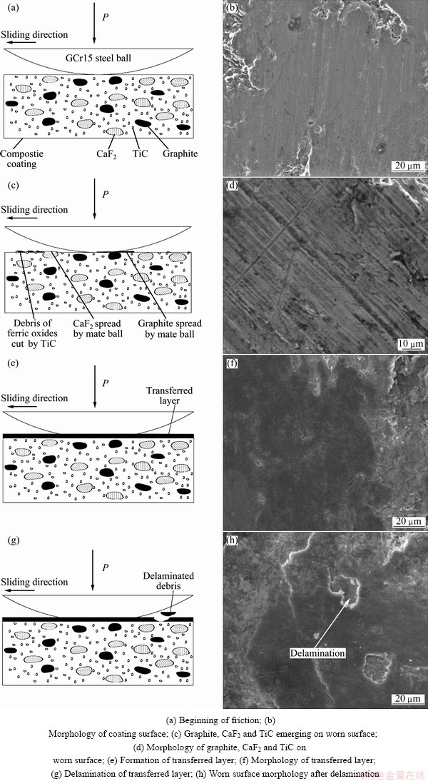
Fig. 8 Mechanism models of generation and failure process of transferred layer on composite coatings
4 Conclusions
1) Friction coefficients of the graphite/CaF2/TiC/ Ni-base alloy composite coatings are in the range of 0.22-0.288, which are reduced by 25.9%-53% compared with those of pure Ni-base alloy coatings, and the wear rates of the former are 18.6% to 70.1% less than those of the latter.
2) When wear against GCr15 steel ball, a transferred layer mainly composed of ferric oxides, graphite and CaF2 may gradually develop on the worn surface of the composite coatings, which makes the friction and wear between GCr15 steel ball and the composite coatings change into that between the former and the transferred layer. So the friction coefficients and wear rates of the composite coatings are greatly reduced because of the solid lubrication effect of the transferred layer.
3) The transferred layer protects the composite coatings. As a result, the wear resistance of the coating is improved. The main wear mechanism of the composite coatings is the delamination of the transferred layer in friction process.
References
[1] LI Zhen-sheng, YANG Min-gan, QIAN Han-cheng, GAO Xin-hai. Modern surface engineering technology [M]. Beijing: China Machine Press, 2007. (in Chinese)
[2] CARRASQUERO E J, LESAGE J, PUCHI-CABRERA E S, STAIA M H. Fretting wear of HVOF Ni-Cr based alloy deposited on SAE 1045 steel [J]. Surface and Coatings Technology, 2008, 202(18): 4544-4551.
[3] LIU Sheng-lin , ZHENG Xue-ping, GENG Gang-qiang. Dry sliding wear behavior and corrosion resistance of NiCrBSi coating deposited by activated combustion-high velocity air fuel spray process [J]. Materials and Design, 2010, 31(2): 913-917.
[4] XU Bin-shi, WANG Hai-dou, DONG Shi-yun, JIANG Bin. Fretting wear-resistance of Ni-base electro-brush plating coating reinforced by nano-alumina grains [J]. Materials Letters, 2006, 60 (5): 710-713.
[5] CHEN Y, WANG H M. Microstructure and wear resistance of a laser clad TiC reinforced nickel aluminides matrix composite coating [J]. Materials Science and Engineering A, 2004, 368(2): 80-87.
[6] ZHANG Tian-ming. Microstructure and abrasive resistance of nano-Al2O3/Ni coating plasma-sprayed [J]. Physics Examination and Testing, 2007, 25(4): 15-18. (in Chinese)
[7] LIU Xiu-bo, SHI Shi-hong, GUO Jian, FU Ge-yan, WANG Ming-di. Microstructure and wear behavior of γ/Al4C3/TiC/CaF2 composite coating on γ-TiAl intermetallic alloy prepared by Nd: YAG laser cladding [J]. Applied Surface Science, 2009, 255(11): 5662-5668.
[8] CAI Bin, TAN Ye-fa, TU Yi-qiang, WANG Xiao-long, TAN Hua. Tribological properties of Ni-base alloy composite coating modified by both graphite and TiC particles [J]. Transactions of Nonferrous Metals Society of China, 2011, 21(11): 2426-2432.
[9] SHI Miao-sen. Solid lubricating technology [M]. Beijing: China Oil Industry Press, 1998. (in Chinese)
[10] WOJCIECH  RAFAL C, NORBERT R, JOANNA B J. Plasma-sprayed composite coatings with reduced friction coefficient [J]. Surface & Coating Technology, 2008, 202(2): 4578-4582.
[11] ZHANG Xiao-feng, ZHANG Xiang-lin, WANG Ai-hua, HUANG Zao-wen. Microstructure and properties of HVOF sprayed Ni-based submicron WS2/CaF2 self-lubricating composite coating [J]. Transactions of Nonferrous Metals Society of China, 2009, 19(1): 85-92.
[12] BOWDEN F P, TABOR D. The friction and lubrication of solids (part II) [M]. Oxford: Clarendon Press, 1964: 32-33.
[13] BOWDEN F P, TABOR D. An introduction to tribology [M]. Beijing: China Machine Press, 1982: 57-60. (in Chinese)
[14] BHUSHAN B. Introduction to tribology [M]. Beijing: China Machine Press, 2006: 121-122. (in Chinese)
[15] WU Yun-xin, WANG Fu-xing, CHENG Yin-qian, CHEN Nan-ping. A study of the optimization mechanism of solid lubricant concentration in Ni/MoS2 self-lubricating composite [J]. Wear, 1997, 205(1-2): 64-70.
[16] WANG Jun-xiang, GU Ming-yuan. Investigation of CaF2 filler and carbon fiber on the tribological properties and wear mechanisms of nylon1010 composites [J]. Polymer Materials Science and Engineering, 2005, 21(3): 184-187. (in Chinese).
石墨/CaF2/TiC协同改善镍基合金喷涂层的摩擦磨损行为与机理
蔡 滨,谭业发,何 龙,谭 华,王小龙
解放军理工大学 野战工程学院,南京 210007
摘 要:为了降低机械零件在强烈摩擦磨损条件下的摩擦因数,提高其耐磨性,制备了等离子喷涂石墨/CaF2/TiC/镍基合金复合涂层,研究其摩擦学行为及机理。结果表明,石墨/CaF2/TiC/镍基合金复合涂层的摩擦因数为0.22~0.288,较纯镍基合金涂层的降低了25.9%~53%,磨损率较之降低18.6%~70.1%。与GCr15钢球对摩时,复合涂层的磨损表面逐渐形成了由铁氧化物、石墨和CaF2组成的转移层,使GCr15钢球与复合涂层的摩擦转变为钢球与转移层的摩擦。由于转移层起到固体润滑作用,复合涂层的摩擦因数和磨损率大幅度降低。复合涂层的主要磨损机理是转移层在载荷的反复作用下而产生的层脱剥落。
关键词:等离子喷涂;复合涂层;镍基合金;石墨;TiC;CaF2;摩擦学
(Edited by Xiang-qun LI)
Corresponding author: Ye-fa TAN; Tel: +86-25-80821055; E-mail: tanyefa7651@163.com
DOI: 10.1016/S1003-6326(13)62475-9

