Article ID: 1003-6326(2005)06-1333-08
Microstructure and wear properties of tungsten carbide reinforced steel matrix composites
YOU Xian-qing(������)1, SONG Xue-feng(��ѩ��)1,
REN Hao(�� �)1, MA Jian-guo(������)2,
HUANG Man-ping(����ƽ)2, ZHANG Cheng-jun(�ųɾ�)1
(1. Institute of Material Science and Engineering, Hefei University of Technology,
Hefei 230009, China;
2. Anhui Architectural Engineering College, Hefei 230022, China)
Abstract: WC(27%) reinforced steel matrix composites were produced by using an electroslag melting casting technique. The microstructure of the material was characterized using scanning electron microscopy(SEM), optical microscopy and X-ray diffraction(XRD). Energy dispersive spectroscopy(EDS) and transmission electron micro-scopy were performed to investigate the interfacial composition between WC particle and steel matrix. The results reveal that the WC particles are partially melted into the steel substrate. At the same time, a reaction layer was detected along with the periphery of WC particle, which significantly enhances the bonding strength of the interface. A slipping wear (high stress abrasion) test was utilized to understand the wear behavior of this material. Abrasive experiment displays a better wear resistance than unreinforced steel matrix when coarse WC particles are dispersed into it. The coarse particles provide greater wear-resistance than the fine particles and operatively takes on the most applied loads. Additionally, the large particles have not been peeled during the wear process for a long time, which indicates the effect of interfacial reaction on wear behavior at the ambient temperature. A double carbide (Fe, W)3C is detected in the interface zone between particles and matrices using transmission electron microscopy.
Key words: electroslag melting casting; WC particle; interface reaction zone; wear CLC
number: TG331 Document code: A
1 INTRODUCTION
Particulate-reinforced metal matrix composites(PMMCs) are well known for their higher specific modulus and strength as well as excellent wear resistance when compared with their monolithic counterparts. Therefore, PMMCs have served as an important class of high performance materials for use in aerospace, automotive and mining industries. Metal matrix composites containing a high volume fraction of carbide, nitride, boride and/or oxide particles are frequently the choice of materials for applications which require good wear resistance[1-4]. Tungsten carbide has high hardness, good wear resistance and impact as well as strong wetting cohesion between duplex phase, i.e. WC phase and matrix phase.
Over the last decade, attempts to produce WC particle reinforced steel matrix composites have intensified. Generally, there are two ways to obtain a high mass fraction of WC particles in steel: through casting method[5-7] or via powder metallurgy(P/M) processing techniques[8-10]. Additionally, WC has been incorporated into the surface region of Fe-based or Ni-based alloys through laser cladding[11-13]. The aim of these methods is to manufacture a composite materials combining attractive properties from different materials. However, it is often difficult to achieve the benefits of casting methods or conventional powder metallurgy route because of inhomogeneous distribution and clustering. Clustering is often accompanied by porosity, which reduces the wear resistance of the composite[14, 15]. Furthermore, if the bonding force between particles and matrix is poor, the mechanical properties are drastically decreased[16].
Electroslag melting casting process combined powder metallurgy and metallurgical melting casting is a new productive process, which is utilized to produce particulate-reinforced metal matrix composite. Production of PMMCs by the eletroslag melting casting technique provides a potential advantage because the microstructure combined with the reinforcement of WC particles is free from macro segregations[17]. Compared with the traditional powder metallurgy route, the eletroslag melting casting process represents a good contact between particle and matrix where an interfacial layer has been detected. It is contributed to the increase of the intensity of interface combinations, because the formation of the interface reaction zone is combined by the power chemical valence which elevates the resistance to applied loads. Another advantage is the possibility to produce large components. As for the conventional casting materials, segregation of the particles can be a problem because of the slow cooling rate. However, when the velocity of the solidification front has to exceed a critical value in order to ensure that particles are engulfed and not pushed ahead of the solidification front[14, 18], the distribution of the particles remains relatively homogeneous in this way. However, the melting chamber of electroslag melting casting process has a cooling system using cold water apart from the melting of electrode in the form of liquid drip, which can make the velocity of cooling reach the critical magnitude. Additionally, an electric magnetic stirrer is employed to mingle WC particles with matrix sufficiently. Therefore, the electroslag melting casting process can avoid the shortcomings of two methods mentioned above.
In our present work, WC(27%) reinforced steel matrix composites were successfully produced by using the electroslag melting casting technique. On the basis of previous literatures, the coarse grade WC particulates were selected intentionally into steel matrix molten to evaluate effects of interfacial reaction between WC particle and steel matrix on wear behavior of bulk composites.
2 EXPERIMENTAL
2.1 Sample preparation
Commercially available WC particles(mean size to 60��m) and carbon steel powders as additive were used as original powders, abandoned GCr15 bearing steel acted as raw matrix materials. It is noted that a small amount of alloy elements should be entered into melt to achieve stoichiometry in the materials. A cast made from steel matrix composite with 27% WC was produced using the electroslag melting casting. Basically, the electroslag melting casting of WC particles reinforced steel matrix composites route includes:
1) An electrode was fabricated from the mixed raw powders and GCr15 bearing steel using a medium frequency inducing furnace.
2) The electrode was melted in the form of liquid drip through a single beam vertical electroslag furnace.
3) Consolidation of melt.
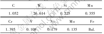
The composition of casting materials measured by an optical spectrometer(OE SPECTROMETER ARL-4460) is shown in Table 1.
Table 1 Chemical composition of WC/steel-based composite by electroslag melting casting(mass fraction, %)
Metallographic specimens were cut to size of 10mm��10mm��15mm using an electrical discharge machining. The composite plates were machined into small rectangular shape for sliding wear testing using the same machining. This was followed by annealing process for 2h at temperature of 880��, then cooled in furnace to 740�� and remained 8h at that temperature, finally, the samples were cooled to room temperature in the stove. The finishing treatment was applied to specimens. The as-pretreated specimens had been immediately hardened in the oil tank at 950�� before they were tempered for another 3h at low temperature of 180��.The ultimate hardness of samples is HRC65.
2.2 Abrasive wear testing procedure
Dry slipping wear test was carried out on a MM200 wear-test machine at the ambient temperature. The test involved the wear of the flat plane (8mm��30mm) of a rectangular pin (8mm��8mm��30mm) of sample material in contact with an wear rings made from GCr15 bearing steel with a hardness of HRC 58-62, which was derived from quenching firstly in oil media at 860�� before they were tempered for 3h at low temperature of 160��. The constant load was 400N, the rotative velocity was 200r/min. The average width of wear groove was measured with the help of microscope, the wear volume was calculated by the following formula:
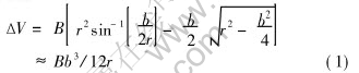
where B is the width of wear ring, mm; b is the width of wear groove, mm; r is the outer radius of wear ring, mm; ��V is the wear volume, mm3.
2.3 Characterization
Room-temperature X-ray diffraction(XRD) (D/Max-rB, Rigaku, Japan) was performed to the samples for phase determination with CuK�� radiation. The XRD diffraction patterns were collected in a 30-80�� angle range and at a 0.02�� angle step.
Scanning electron microscope(SEM) and light optical microscope were used to characterize the microstructure of as-treated terminally materials.
Energy dispersive spectroscopy(EDS) and transmission electron microscope(TEM) were performed to investigate the interfacial composition between WC particles and matrix.
3 RESULTS AND DISCUSSION
3.1 Microstructure
The morphology and spatial distribution of WC particles in the composite materials are shown in Fig.1. WC particles are dispersed homogeneously in the steel matrix and obvious particles clustering isn��t detected. Only some fine carbides are prone to clustering, which are derived from precipitation of compound carbides, but the coarse particles almost isolate each other. The composites contain large, round WC particles along with much small particles dispersed between the large ones(Fig.2) and a large amount of smaller, rounder WC or compound cemented carbide with more uniform size distribution in the steel substrates are detected. Additionally, some large, angular WC particles isolated are emerged in Fig.1. Thus, WC particles in as-consolidated composites can be classified into three types. Class �� is large, oval or round WC particle, class �� is large, angular WC particle, class �� is smaller particle produced in-situ or during recrystallization.
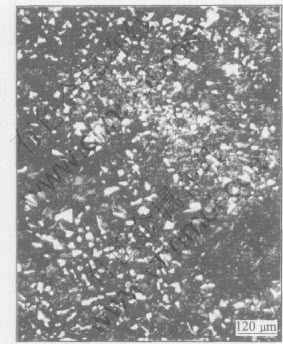
Fig.1 Microstructure of WC/steel matrix composite at lower magnification
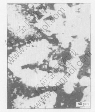
Fig.2 Optical micrograph of class �� WC particles
Class �� is actually remnants of some original WC particles dissolved partly in the rim during the electroslag melting casting process whose work temperature is over 2000��. These initial WC particle aren��t dissolved and remain basically its initial shape. As the thermodynamics property in the sharp angle of WC particle is prone to unstablility, the sharp angle is preferentially solubilized to be a round arc. Although the operational temperature is much higher than other processing such as traditional casting method, WC particulates still retains in the process because the work time is extremely short. Solution is performed firstly in the acute angle with small curvature radius, high surface energy and thermodynamic unstability, which can be characterized as effect of particle rim.
Class �� is initial WC particle in the raw powders with high chemical stability. Even though they are in the temperature of over 2000��, no interfacial reactions are evident in interface. The interface zone between them is clear and straight compared with class �� whose interface is very obscure due to interface reactions(see Fig.3).
Class �� is very small whose average diameter is not larger than 5��m. They derive from in-situ precipitation of WC particles or recrystallization in the process. Although the number of class �� is large, a small number of large particles contained in the composites cover more volume than the small particles, for examples, the average diameter of large WC particles is approximately 55��m which take up about 30% of the composite in volume, which provides the prerequisite to remarkable wear resistance of the composites.
Fig.4 shows a typical micrograph of individual partially dissolved particle. An obvious reaction layer whose thickness reaches several microns beyond the amount of conventional solution-diffusion zone is detected. During the process of WC
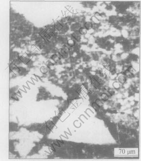
Fig.3 Boundary shape of class �� WC particles
dissolution and decomposition at the steel matrix interface, W atoms are released which are dissolved into Fe during exposure to high temperature. Simultaneously, inter-dissolution between WC particles and matrix is performed generating W and Fe atoms. When the appropriate concentration of W atoms build up in front of the rim of WC particles, on the basis of author��s previous studies[17], the reaction can occur to form Fe3W3C. A reaction layer with proper thickness can improve the bonding strength of WC and matrix as well as dramatically enhance mechanical properties of the monolithic composites. Moreover, the dissolution of WC which can blunt the sharp angle of WC contributes to relief of stress concentration, at the same time, promotes the strength-toughness combination of materials.
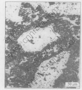
Fig.4 Reaction layer at edge of large WCp in composite
Fig.5 shows a line scan profile for the Fe and W elements which displays the contents of W element near the rim of a singular WC particle are higher than that of beyond the periphery of the WC particle.
The results of XRD analysis (see Fig.6) confirms the existence of Fe3W3C phase. Meantime, WC, Cr23C6, ��-Fe and Cr7C3 are detected in the specimen made from WC particles reinforced GCr15 bearing steel matrix composites.
3.2 Tribological property
3.2.1 Wear mechanism
Fig.7 shows the worn surface of GCr15 bearing steel composites reinforced with large WC particles. When the composite materials are worn against the ring made from GCr15 bearing steel
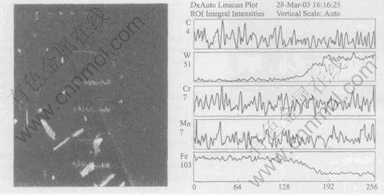
Fig.5 Line scan profiles of elements of WC/steel composites
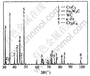
Fig.6 XRD pattern of WC/steel composites
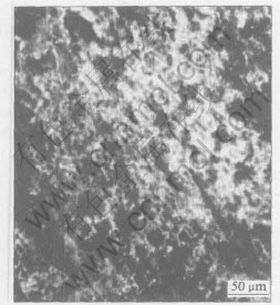
Fig.7 Worn surface of experimental material
under a 400N load, the imprint of adhesion effect and plastic deformation of matrix is not apparent in the worn surface of composite materials. However, ploughing grooves which are representative behavior of abrasive grain wear are revealed parallel to sliding orientation of specimens. These grooves are caused by the ploughing action of fragments or squeezed between the sliding surface and produced by the hard asperity of contacting surface during the wear process.
At the first stage, the hard phase take on primarily the applied loads after surface of specimen is worn to be flat. At the moment, ploughing activities of particles are conducted on the specimen surface. On the other hand, steel matrix only braces the WC particles and the coarse carbides protect the matrix from damage of the applied stress. With the wear testing going on, the width and depth of ploughing grooves are drastically increased.
However, the WC particles embeded into composite under constant loads are fractured by the tangential frictional forces after a long time. There are some wear debris (shown in Fig.7) in the form of particle chips generated along the periphery of the ploughing grooves. The wear debris trapped into slipping face deteriorate the specimen��s failure. At the end, once the particles are peeled, a large volume of matrix are exposed to the tangential frictional forces, which get rise to flying increase of wear loss rate. Consequently, as the thickness of reaction layer is controlled under a critical value, composites reinforced by coarse WC particles are provided better crack strength in interface, which makes the WC particles uneasily peeled.
3.2.2 Effect of WC particles on wear resistance
Fig.8 shows the variation of volume loss with wear time for the composites reinforced with WC particles and the unreinforced GCr15 bearing steel under the same conditions. Apparently, the volumetric wear of GCr15 bearing steel increases rapidly with the wear time. On the other hand, WC particles reinforced steel matrix composites experience a stability in volumetric wear with the elongation of wear time, indicating that hard WC particles can protect the steel matrix effectively during sliding wear. The volume loss of WC reinforced composites ranges primarily from 2mm3 to 3mm3. Meanwhile, the dependence of volume loss on wear time is approximately flat linear in WC reinforced composites, and the relationship displays that the stable stage of wear is longer than that of GCr15 under the same conditions. Therefore, these merits make WC reinforced composites attractive for the industrial applications which are required to wear resistance.
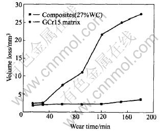
Fig.8 Relationship between wear volume and wear time of composites
3.2.3 Effect of WC particles size on wear resistance
The previous work had some attempts to investigate the wear resistance of equivalent composites containing 40% WC particles(mean size is 8��m)[19]. As compared with variation of present study as Fig.9. it is clear that the composite with few contents of coarse WC particles (60��m) have better wear resistance than the one with more contents of fine WC particle(8��m). Particularly, the longer the wear time is, the more obvious the advantages of composites with 27% large WC are.
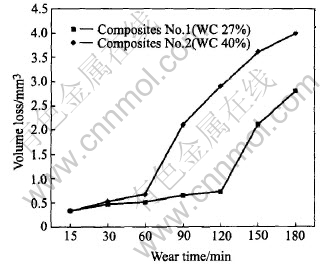
Fig.9 Variation between wear loss volume and wear time in WC/steel composites with different grain sizes
Therefore, although the number of reinforcement phase affects decisively the wear property of composites, the wear resistance is not unvariedly proportional to the amount of particles. What is more, it is the key to improving the strength of boundary bonding in terms of hard phase and matrix. High bounding strength makes WC particles uneasily peeled from the steel matrix as well as elevates the capacity of resistance to applied loads.
Based on the contexts mentioned above, a reaction layer which promotes interfacial bonding intensity and enhances the protecting effect to matrix provided by large WC particles is emerged in the vicinity of coarse WC particles. Thus, the substrates under heavy loads could effectively transmit most stress to large WC particles, the drop-out of flint particles is confined as well. On the other hand, the small WC particles in the composites show the characteristic of easy shedding when worn under the same conditions. The reason is that during dry slipping with heavy loads, small WC particles are subjected to peel in view of the lower depth of penetration into the matrix by the presence of fine WC particles. Subsequently, wear chips resulted from the peeled particles are clamped between ring and sample and combine with them to become three-body sliding abrasion, which destroys critically the surface and increases drastically the wear rate. At the same time, it is obvious that adhesion effect and plastic deformation are taken place in fine WC particles reinforced composites during the wear testing, which further deteriorates the wear of surface. Moreover, a previous literature[20] also pointed out that the interfacial reactions layer generated in the rim of fine WC particle is looser and weaker than that of large WC particle, which is often companied by pore. This is possibly one of the reasons to interpret the results attained from Fig.9.
The result presented in Fig.10(a) demonstrates that no drop of large WC particles (60��m) is evident in the worn surface during the abrasive wear process. However, some pits and white patches are detected in Fig.10(b). The worn surface is associated with plastic flow and adhesion effect as well as the removal of WC particles. The pits are generated from the removal of fine WC particles and the white patches are the matrix on the worn surface removed recently in terms of adhesion effect.
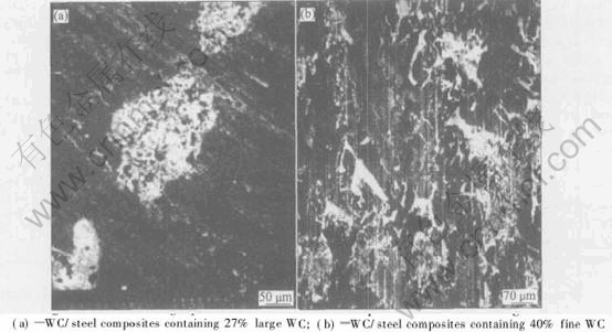
Fig.10 SEM micrographs of wear surface of composites with different grain sizes
Fig.11 shows the pronounced micrograph of large WC particle dissolved in the core on the worn surface. It reveals that no removal of WC particles and some cracking(arrows) are evident in this micrograph. The crack occurs intragranularly and no cracking emerges in the matrix of the composite with large particles, which implies that the applied loads are predominantly transported to WC particles, meanwhile, WC particles release the loads through initiation and propagation of crack.
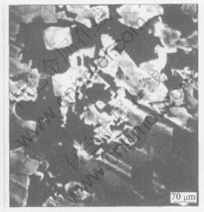
Fig.11 SEM morphology of intragranular crack of coarse WCp on worn surface
3.2.4 Effect of interfacial reaction on wear resistance
The WC particles reinforced steel matrix composite systems are characterized by interfacial reactions between WC particle and matrix. It is important to control the thickness of reaction layer within a critical value. In general, if interface reactions are not controllable at an acceptable level, particles deterioration can occur and its load bearing capacity is reduced or, eventually even lost completely. Interfacial reactions can change the composition of the matrix through diffusion of alloy element at high temperature. It is observed that structural changes occur not only via the interfacial reactions between WC and matrix, but also through constituent change in the matrix itself by virtue of influx of alloy atoms. Therefore, controlling the interface reactions is essential to generate a strong and satisfactory PMMCs.
Most of the authors estimating interface reactions in PMMCs[21], agree that reaction rates between matrix and reinforcing agent conform to a diffusion controlled parabolic relation according to:
x2=kt(2)
where x is the reaction zone width, t is the time of the reaction and k is the reaction rate constant. From the reaction zone width, k is determined according to Eqn.(2), however, the reaction zone width (x) can be estimated on micrographs. The temperature dependence of the rate constant can be explored by the common relation:
k(T)= k0exp(-Eeff/RT)(3)
where k0 is a constant.
These equations provide the control of interfacial reaction with useful information. Commonly, we can adjust the operation temperature and molten time to obtain an acceptable thickness of reactions layer. If the value of thickness of reaction zone is very high beyond the critical value, the resistance to wear reduces. The reason is that not only for property of thick interface layer to easily peel but also for the particulate itself destruction result in the reduction of capacity of particle strengthening, which drastically causes the ability of resistance to wear decrease. On the other hand, the thickness is too thin to supply good bonding strength in the interface. Thus, the contradictory trends can be reconciled only by a reasonable compromise, i.e. there is objectively a critical value of interface layer thickness. A desirable reaction layer with suitable thickness can enhance the wear resistance and perfect the physical compatibility for WC particle and matrix as well as relieve the heat stress in the matrix due to differences of elastic modulus and heat expansion coefficient between WC particle and matrix.
4 CONCLUSIONS
1) Using the electroslag melting casting technique, an outstanding bearing steel matrix reinforced with coarse WC particles, with an interfacial reaction layer with a thickness of 3-4��m, consisting of Fe3W3C, was successfully produced. The interfacial reaction layer can improve the physical compatibility between WC and matrix as well as elevate the interface bonding strength.
2) The representative micrographs show there are three types of WC particles in the as-consolidated steel matrix composites. Class �� is large, oval or round WC particle, class �� is large, angular WC particle, class �� is smaller particle produced in-situ or recrystallization. The properties and physical condition differ distinctly from each other.
3) The wear resistance of the tested materials against sliding wear shows excellent results. The wear tests demonstrate that composites reinforced with large WC particles have better wear resistance than composites unreinforced. Coarse WC particles can provide a better protection to the steel matrix from action of the tangential frictional forces. Meantime, the presence of large WC particles in the matrix impedes the adhesion effect and plastic deformation at the worn surface. Additionally, in comparison with the wear resistance of composites reinforced with 40% fine WC particles, the wear volume loss of latter is higher than that of the present testing materials. The reason is that high interfacial bonding strength resulted from suitable interfacial reactions between large WC particle and matrix constrains the removal of WC particles. Further, it remarkably improves the resistance to wear.
4) For the PMMCs, it is worth noting to control the thickness of interfacial reactions. A desirable interfacial reaction layer can drastically promote the wear resistance.
ACKNOWLEDGEMENTS
The authors would like to thank the supports of the Laboratory Center of Institute of Material Science and Engineering at Hefei University of Technology.
REFERENCES
[1]Berns H, Wewers B. Development of an abrasion resistant steel composite with in situ TiC particles [J]. Wear, 2001, 251: 1386-1395.
[2]Velasco F, Gordo E, Isalel R. Mechanical and wear behavior and high speed steel reinforced with TiCN particle [J]. International Journal of Refractory Metal & Hard Material, 2001, 19: 319-323.
[3]Dogan O N, Hawk J A, Tylczalt J H. Wear of cast chromium steel with TiC reinforcement [J]. Wear, 2001, 250: 462-469.
[4]Quercia G, Grigorescu I, Contreras H, et al. Friction and wear behavior of several hard materials [J]. International Journal of Refractory Metals & Hard Materials, 2001, 19: 359-369.
[5]Lindroos V K, Talvitie M J. Recent advances in metal composites [J]. Journal of Materials Processing Technology, 1995, 53: 273-284.
[6]Pagonnis E, Lindroos V K. Processing and properties of particulate reinforced steel matrix composites [J]. Materials Science and Technology, 1998, A246: 221-234.
[7]Upadhyaya G S. Cemented Tungsten Carbides -Production, Properties and Testing [M]. Norwich, NY, USA: William Andrew Press, 1998.
[8]Luyckx S, Osborne C, Cornish L A, et al. Fine-grained WC-VC-CO hardmental [J]. Powder Metall, 1996, 39(3): 210-212.
[9]Deng X, Patterson B R, Chawla K K, et al. Mechanical properties of a hybrid cemented carbide composite [J]. International Journal of Refractory Metals & Hard Materials, 2001, 19: 547-552.
[10]Rosa L G, Amaral P M, Anjinho C, et al. Fracture toughness of solar-sintered WC with CO additive [J]. Ceramics International, 2002, 28: 345-348.
[11]Cerr W, Martinella R, Mor G P, et al. Laser deposition of carbide-reinforced coatings [J]. Surf Coat Technol, 1991, 49: 40-45.
[12]Cottrell A H. Cohesion in tungsten carbide [J]. Mater Sci Technol, 1995, 11: 209-212.
[13]Li Q, Lei T Q, ZHANG Y Z, et al. Microstructure of laser clad (WC+W2C)P/Ni based alloy composite coatings [J]. Materials Science &Technology, 2002, 10(1): 5-10.(in Chinese)
[14]Clyne T W, Withers P J. An Introduction to Metal Matrix Composites [M]. Cambridge: Cambridge Univ Press, 1993.
[15]Dogan O N, Hawk J A, Tylczak J H, et al. Wear of titanium carbide reinforced metal matrix composites [J]. Wear, 1999, 225-229: 758-769.
[16]Pelleg J. Reactions in the matrix and interface of the Fe-Sic metal matrix composite system [J]. Materials Science and Technology, 1999, A269: 225-241.
[17]YOU X Q, WANG J C, REN H, et al. Micro defects in tungsten carbide particulates reinforced steel matrix composites by eletroslag melting casting [J]. The Chinese Journal of Nonferrous Metals, 2004, 14(4): 646-651. (in Chinese)
[18]Parasiris A, Hartwig K T. Consolidation of advanced WC-CO powders [J]. International Journal of Refractory Metals & Hard Materials, 2000, 18: 23-31.
[19]YOU X Q, REN H, SONG X F. The effects of WCP contents on the wear resistance of electroslag WC/GCr15 composites [J]. Foundry, 2004, 53(10):792-794.
[20]WANG X, HU H Q. Interface of WCp/Fe-Ni steel matrix composite [J]. Journal of Iron and Steel Research, 1998, 10(4): 46-49.(in Chinese)
[21]Howe J M. Bonding, structure and properties of metal/ceramics interface(Part ��)��Chemical bonding, chemical reaction and interfacial structure [J]. Intl Mater Rev, 1993, 38(5): 233-256.
(Edited by YUAN Sai-qian)
Foundation item: Project(2003KJ016ZD) supported by the Science Research Foundation of Department of Education of Anhui Province, China
Received date: 2005-03-21; Accepted date: 2005-07-01
Correspondence: YOU Xian-qing, Professor; Tel: +86-551-2902961; Fax:+86-551-2905383; E-mail: songxuefeng111@tom.com

