
Cold extrusion deformation behavior of
medium carbon steel after quenching and tempering
HU Cheng-liang(胡成亮)1, ZHAO Zhen(赵 震)1, YIN Guan-ren(尹冠人)1,
YUAN Zhao-feng(袁兆峰)2, XU Xiang-long(徐祥龙)2
1. Department of Plasticity Technology, Shanghai Jiao Tong University, Shanghai 200030, China;
2. Jiangsu Sunway Precision Forging Co., Ltd., Dafeng 224100, China
Received 10 August 2009; accepted 15 September 2009
Abstract: By taking 40Cr as a specific object, cold extrusion deformation behavior of medium carbon steel after quenching and tempering was studied by experimental works. The influence of deformation extent (10%-50%), cone angle of die (90?-120?), hardness after quenching and tempering (HRC21-29) and lubricated condition on the forming load was analyzed. The results show that there is no central bursting and micro crack in the inner of the extruded specimen, and the forming quality is good. The double-peak phenomenon takes place at the front-end of the specimen; the double-peak index increases with deformation extent, and larger deformation can avoid the double-peak phenomenon. The deformation extent is the most important influencing factor, and the lubricated condition almost has no influence, which means that the phosphate coating plus soap process is still a proper lubrication method for cold extrusion of medium carbon steel after quenching and tempering. By investigating the microscopic structure before and after deformation, the initial equiaxed grain is elongated in the extrusion direction, and this feature is more significant at the front-end of specimen.
Key words: medium carbon steel; quenching and tempering; cold extrusion; deformation behavior; microstructure
1 Introduction
40Cr (AISI 5140 or 41Cr4) is a medium carbon steel. This kind of material has good combination property with proper strength, plasticity and ductility after quenching and tempering treatment, and it is always used to manufacture various types of auto parts such as gears, axles, and steering knuckles[1-3]. Forging is an important forming method of these auto parts. To investigate the warm forging and hot forging formability, the changing rule of the flow stress of AISI 5140 in the temperature range of 650-850 ℃ in warm forging has been analyzed systematically through thermo-mechanical experiments[4], and the hot working response of a 41Cr4 steel has been investigated by means of torsion tests at temperatures of 850, 950 and 1 050 ℃[5]. To improve the cold formability, annealing treatment is commonly used in cold forging[6-8].
To obtain good mechanical behavior, about 2/3 of the medium carbon steel forgings need quenching and tempering treatment after forging in practice[9]. However, heat treatment processes often cause excessive and uncontrolled distortion[10-12]. The dimension accuracy of forgings which is influenced by the distortion takes place during the quenching and tempering, and unqualified parts will be produced, especially in cold precision forging. In order to overcome the shortcoming, the cold extrusion deformation behavior of medium carbon steel (such as 40Cr) after quenching and tempering was studied by experimental works, and all these will be contributed to the net-shape forming of auto cold forgings.
2 Experimental
2.1 Workpiece and die
The material of workpiece was 40Cr. To avoid the distortion caused by heat treatment process, the cutting billets were quenched and tempered firstly. The quenching and tempering treatments consisted of heating up to 850 ℃ in vacuum furnace and water quenching and then tempering at various temperatures, i.e., at 580, 600 and 630 ℃, and holding at these temperatures for 120 min before cooling to room temperature; at last the billets with different hardnesses were obtained. Cylindrical
workpieces with external diameter of 35.0 mm and height to diameter ratio of 1?1 were obtained after machining. As shown in Fig.1, the lubrication film is deposited on the workpiece surface through zinc phosphate coating and soaping process. The forward extrusion die used in the study is presented in Fig.2. The material of the punch was Cr12MoV, and material of the punch sleeve was 40Cr. Combined die was used, double-layer die was used under small deformation, triple-layer die was used under larger deformation (such as εF=50%), and die core material was high-speed steel W6Mo5Cr4V2. The experimental condition can be changed by changing the core of die.
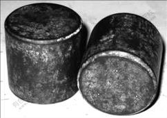
Fig.1 Workpiece after phosphate coating and soaping process

Fig.2 Schematic map of forward extrusion die
2.2 Experimental scheme and method
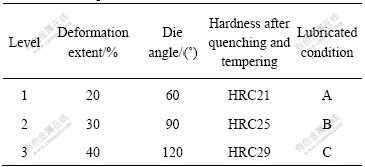
Nonlinear behavior of the process parameters can be determined if more than two levels are used. To reduce the number of experiment, the experimental scheme was arranged by orthogonal experimental design method. And the parameters were analyzed at three levels, as shown in Table 1. Four influencing parameters were considered important to this experiment viz. parameter 1, deformation extent; parameter 2, die angle; parameter 3, hardness after quenching and tempering; and parameter 4, lubricated condition. Table 1 depicts the various
parameters with their corresponding levels. The levels of each parameter were decided from prior experience and the existing conditions. The response variable was discussed. H is represented as the average hardness of the billet after quenching and tempering, H=HRC21 means low level hardness; H=HRC25 means middle level hardness and H=HRC29 means high level hardness. Lubricated condition A was phosphate coating plus soap treatment (P-S treatment), and lubricated condition B was P-S treatment combined with lard coating, and lubricated condition C was P-S treatment combined with lard and MoS2 coating. Furthermore, under the condition of die angle α=120?, another 5 extrusion experiments with different deformation extents (such as 10%, 15%, 25%, 35% and 50%) were also arranged. Therefore, 14 extrusion experiments with different conditions were performed in this study totally. The load-stroke curve was recorded by the forming load measurement system during the extrusion test, and metal flow lines, internal forming defects and microstructure were also investigated.
Table 1 Process parameters and their levels
3 Results and discussion
3.1 Forming quality
The extrusion parts with good surface quality were obtained after forward extrusion, as seen in Fig.3. To observe the internal defects, the extrusion specimen was subdivided along the longitudinal axis of symmetry using wire EDM. Central bursting phenomenon does not take place at the inner of the specimen, and no micro cracks are found by using high power microscope. Therefore, the forming quality of the extrusions is good. After grinding the finishing cross-section of the specimen that is eroded by 1?1 hydrochloric acid (75 ℃) and washed by water, and washed by 15% nitric acid subsequently, then flushed by clear water, and finally washed with absolute ethyl ethanol, the metal flow lines was obtained after hot air drying. The flow lines (Fig.4) are continuous and the distribution is reasonable in the extrusion direction.
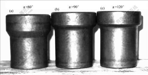
Fig.3 Extrusion parts (εF=30%)

Fig.4 Metal flow lines of extrusions (α=120?): (a) εF=10%; (b) εF=50%
3.2 Double-peak phenomenon
There is double-peak phenomenon (Fig.5) at the front-end of the extrusion during the experiment. Because of bad material flowability after quenching and tempering, the center of billet comes into the plastic state later and the flow velocity is smaller. At the same time, the flow velocity of the surface is smaller due to friction. Therefore, the larger flow velocity occurs in the region between the surface and the center. The velocity difference is the main reason of the double-peak phenomenon. To analyze the relationship between the double-peak phenomenon and the deformation extent, the ratio of the projected area of outside of peak ring and the cross-sectional area of the extrusion is defined as the double-peak index, and it is described as
 (1)
(1)
where X is the distance between double-peak; and D is the diameter of the extrusion.
By taking a group of specimen extruded by workpiece with middle level hardness, the distance between double-peak is measured. The double-peak index can be computed according to Eq.(1), and the relationship between double-peak index and deformation extent is shown in Fig.6. When εF=10%, the front-end of
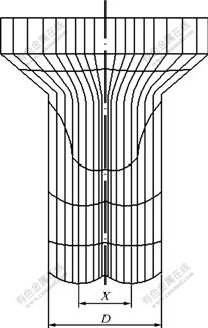
Fig.5 Double-peak phenomenon at front-end of extrusion
extruded specimen is smooth without double-peak, as shown in Fig.4(a)). For εF=15%, the double-peak index increases with deformation. When the deformation extent increases to 50% , the dp value is approximately 90%, as shown in Fig.4(b)). When the deformation extent increases continuously, the metal flow velocity of the center is increased under the large deformation force, and the double-peak phenomenon will disappear.
3.3 Forming load
According to the load-stroke curves collected during the extrusion test, the peak value of forming load is extracted and filled in Table 2. The load of No.1 test is

Fig.6 Relationship between double-peak index and deformation extent
the smallest, only 612 kN, and the load of No.9 test is the largest, 1 154 kN. Based on the analysis method of orthogonal experimental design, the corresponding average values are achieved. According to the change trend of the average value, the load increases with the deformation extent, die angle and workpiece hardness after quenching and tempering. From the analysis results, the impact significant degree of various parameters on the forming load is shown as follows: deformation extent>die angle>hardness after quenching and tempering>lubricated condition. The most significant factor is the deformation extent and the lubricated condition almost has no effect on the forming load. That is to say, during the cold extrusion process of medium carbon steel after quenching and tempering the phosphate coating plus soap treatment plays a major role for lubrication, and lard and MoS2 coating can improve the lubrication condition a little. Thus, the phosphate coating plus soaptreatment is still a proper lubricated method.
Table 2 Analysis of orthogonal array

When α=120?, H=HRC 25, the relationship between the extrusion pressure and deformation extent is investigated. The extrusion pressure increases with the deformation (Fig.7) and the influencing trend is parabolic (p=1 792eF2+1 087eF+480.9). Based on the concept of allowable deformation extent[6], the allowable forward extrusion deformation extent εF(2500)max is about 80% from Fig.7. Obviously, the allowable deformation extent will be reduced correspondingly when the workpiece hardness after quenching and tempering increases.

Fig.7 Relationship between extrusion pressure and deformation extent
3.4 Microstructure
When the microstructure of extrusion specimen is observed, three different locations (surface, 1/2R zone and center) of the plastic deformation area (area I) and the extrusion end (area II) are selected, as shown in Fig.8. Under the condition with middle level hardness, 120? die angle and P-S treatment for lubrication, the microstructure of the specimen before and after cold extrusion with two different deformation extents (10% and 50%) are investigated in detail, and a group of metallographic images are gathered in Fig.9. Because of quenching and tempering treatment, the microstructure of the extrusion specimen is tempered sorbite that is in mechanical impurity of fine cementite and ferrite matrix, and the fine cementite is dispersed in the fine-grained ferrite matrix. When eF=10%, the microstructure after extrusion is almost the same as the initial one, and small deformation has little effect on the grain morphology. When eF=50%, in the area I, the grain in the center is equiaxed grain, just the same as the grain before extrusion,and it is illustrated that only small deformation takes place in the center. Compared with the center, the grain with irregular shape is presented and markedly elongated in the 1/2R zone. Due to larger plastic deformation, the grain shape near the surface is slender along the extrusion direction. Compared with the plastic deformation area, after the die bearing the grains both in the 1/2R zone and near the surface of area Ⅱ are more obviously elongated along the extrusion direction

Fig.8 Sampling location of metallographic observation

Fig.9 Microscopic structures of extrusion specimen (H=HRC 25, α=120?): (a) Before extrusion; (b) Center (εF=10%, areaⅠ); (c) Center (εF=50%, areaⅠ); (d) 1/2R zone (εF=10%, areaⅠ); (e) 1/2R zone (εF=50%, areaⅠ); (f) 1/2R zone (εF=50%, area Ⅱ); (g) Surface (εF=10%, areaⅠ); (h) Surface (εF=50%, areaⅠ); (i) Surface (εF=50%, area Ⅱ)
.
4 Conclusions
1) The surface quality of the extrusion parts is good and there is no central bursting and micro crack in the center. The metal flow line is observed by aciding and its distribution is reasonable. So, the forming quality of extrusion parts is good.
2) The double-peak phenomenon takes place at the front-end of the specimen because of the metal flow velocity difference. Fro εF=15%, the double-peak index increases with the deformation extent. When the deformation extent rises up to 50%, dp value is approximately 90%. Larger deformation can avoid the double-peak phenomenon.
3) The impact significance order of various parameters on the extrusion load is shown as follows: deformation extent>die angle>hardness after quenching and tempering>lubricated condition. The deformation extent is the most important while the lubricated condition has nearly n o influence. Then a conclusion can be drawn that phosphate and soap treatment is still proper in lubrication method for cold extrusion of medium carbon steel after quenching and tempering.
4) By investigating the microscopic structure before and after deformation, the initial equiaxed grain is elongated along the extrusion direction; the grain near the surface is more obviously elongated than that at the center; and this feature is more significant at the end of the extrusion specimen.
References
[1] TAO Jin, WANG Xiao-qun, TAN Jia-zhen. Reliability of gear tooth bending fatigue strength for through hardened and tempered steel 40Cr [J]. Journal of University of Science and Technology Beijing, 1997, 19(5): 482-484. (in Chinese)
[2] GAO Wei-guo, DONG Li-jun, HU Feng-lan, TAN Bo. Analysis of quenching cranking and improvement of heat treatment process for steel 40Cr axle vehicle [J]. Journal of Hunan Institute of Technology, 2008, 18(4): 33-36. (in Chinese)
[3] ZHENG Yu-chun, WU Yu-cheng, LIU Yu, HUANG Xin-min, ZHANG Xian-bin, XU Gao-lai, WANG Wei, WU Si-cheng. Study on technology of forging-remnant-heat hardening of 40Cr automobile turning junction [J]. Hot Working Technology, 2004, 33(3): 47-48. (in Chinese)
[4] LIN Xin-bo, ZHAI Fu-bao, FENG Jian-hua, ZHANG Zhi-liang. Research on the flow stress characteristics of AISI 1006 and AISI 5140 in the temperature range of warm forging by means of thermo-mechanical experiments [J]. Journal of Materials Processing Technology, 2002, 122: 38-44.
[5] EVANGELISTA E, MASINI M, MEHTEDI M E, SPIGARELLI S. Hotworking and multipass deformation of a 41Cr4 steel [J]. Journal of Alloys and Compounds, 2004, 378: 151-154.
[6] RUAN Xue-yu, XIAO Wen-bin, XU Zu-lu. Cold extrusion technology [M]. Shanghai: Shanghai People’s Publishing House, 1963. (in Chinese)
[7] LANGE K. Handbook of metal forming [M]. New York: McGraw-Hill, 1985.
[8] International cold forging group. ICFG Doc. 18/07: ICFG 40 years history document [M]. Bamberg: Meisenbach Verlag, 2007.
[9] WANG Xue-qian, CHEN Zhi-juan. A new technique on finishing the forging and “Q & T” forged of medium carbon constructional steel by one step [J]. Journal of Sichuan Institute of Technology, 1992, 11(1): 41-46. (in Chinese)
[10] TOTTEN G E. Heat treating in 2020: What are the most critical issues and what will the future look like? [J]. Heat Treatment of Metals, 2004, 31(1): 1-3.
[11] KIM S Y, KUBOTA S, YAMANAKA M. Application of CAE in cold forging and heat treatment processes for manufacturing of precision helical gear part [J]. Journal of Materials Processing Technology, 2008, 201: 25-31.
[12] LEE S J, LEE Y K. Finite element simulation of quench distortion in a low-alloy steel incorporating transformation kinetics [J]. Acta Materialia, 2008, 56: 1482-1490.
(Edited by YANG Hua)
Corresponding author: HU Cheng-liang; Tel: +86-21-62813430-8308; E-mail: clhu@sjtu.edu.cn

