Design methods of headed studs for composite decks ofthrough steel bridges in high-speed railway
��Դ�ڿ������ϴ�ѧѧ��(Ӣ�İ�)2011���3��
�������ߣ������� Ҷ÷��
����ҳ�룺946 - 952
Key words��through steel bridge; steel-concrete composite deck; mechanical characteristics; stud; design method
Abstract: Aimed at two typical composite floor systems of through steel bridges in high speed railway, design methods of headed studs were put forward for different composite members through comparing and analyzing the structure, mechanical characteristics and transmission routes of deck loads. The simplified calculation models were brought out for the stud design of the longitudinal girders and transverse girders in the composite floor system of Nanjing Dashengguan Yangtze River Bridge (NDB). Studs were designed and arranged by taking the middle panel of 336 m main span for example. The results show that under deck loads, the longitudinal girders in the composite floor system of through steel bridges are in tension-bending state, longitudinal shear force on the interface is caused by both longitudinal force of ��The first mechanical system�� and vertical bending of ��The second mechanical system��, and studs can be arranged with equal space in terms of the shear force in range of 0.2d (where d is the panel length) on the top ends. Transverse girders in steel longitudinal and transverse girders-concrete slab composite deck are in compound-bending state, and out-of-plane bending has to be taken into account in the stud design. In orthotropic integral steel deck-concrete slab composite deck, out-of-plane bending of transverse girders is very small so that it can be neglected, and studs on the orthotropic integral steel deck can be arranged according to the structural requirements. The above design methods and simplified calculation models have been applied in the stud design of NDB.
J. Cent. South Univ. Technol. (2011) 18: 946-952
DOI: 10.1007/s11771-011-0785-4![]()
HOU Wen-qi(������), YE Mei-xin(Ҷ÷��)
School of Civil and Architectural Engineering, Central South University, Changsha 410075, China
? Central South University Press and Springer-Verlag Berlin Heidelberg 2011
Abstract: Aimed at two typical composite floor systems of through steel bridges in high speed railway, design methods of headed studs were put forward for different composite members through comparing and analyzing the structure, mechanical characteristics and transmission routes of deck loads. The simplified calculation models were brought out for the stud design of the longitudinal girders and transverse girders in the composite floor system of Nanjing Dashengguan Yangtze River Bridge (NDB). Studs were designed and arranged by taking the middle panel of 336 m main span for example. The results show that under deck loads, the longitudinal girders in the composite floor system of through steel bridges are in tension-bending state, longitudinal shear force on the interface is caused by both longitudinal force of ��The first mechanical system�� and vertical bending of ��The second mechanical system��, and studs can be arranged with equal space in terms of the shear force in range of 0.2d (where d is the panel length) on the top ends. Transverse girders in steel longitudinal and transverse girders-concrete slab composite deck are in compound-bending state, and out-of-plane bending has to be taken into account in the stud design. In orthotropic integral steel deck-concrete slab composite deck, out-of-plane bending of transverse girders is very small so that it can be neglected, and studs on the orthotropic integral steel deck can be arranged according to the structural requirements. The above design methods and simplified calculation models have been applied in the stud design of NDB.
Key words: through steel bridge; steel-concrete composite deck; mechanical characteristics; stud; design method
1 Introduction
With the advantages of high rigidity, low construction height, low noises, good vibration absorption and good driving comfort, through steel bridges with composite deck have got wide applications in high speed railway worldwide [1-2]. In composite decks, concrete ballast slab is composited with steel bridge floor system by headed studs. Though there are new kinds of shear connectors, say, PBL [3-4], the headed studs are still the most widely used ones because of non-directional stress and convenient construction. Especially, in railway composite bridges, the studs are universally preferred.
For high speed railway through steel bridges, the structural forms of composite deck are various. There are four main structural forms: 1) Concrete slab composited with both steel floor system and bottom chords of the main trusses; 2) Concrete slab composited with bottom chords only at node areas; 3) Steel longitudinal and transverse girders-concrete ballast slab composite deck; 4) Orthotropic integral steel deck-concrete ballast slab composite deck [2]. In the latest decade, for most of the railway through steel bridges built, abuliding and designing, type 3) and type 4) are the two main types of composite deck adopted. There is no lack of super bridges, for example, ?resund Bridge (Denmark), Garde- Adh��mar Bridge (France TGV), Wuhan Tianxingzhou Yangtze River Bridge of WuGuang passenger special line (China) and Nanjing Dashengguan Yangtze River Bridge (NDB) of Beijing-Shanghai high speed railway (China) [1-2, 5-7].
With the action of deck loads, the deformation of through steel bridges includes two parts: one is the whole deformation of main trusses, and the other is the deformation of composite floor system relative to main trusses [8-10]. The whole deformation of main trusses is mainly vertical bending, which makes most areas of the bottom chords in tension while bottom chords near middle supports (continuous steel truss) in compression. The bottom chords in tension will be stretched and those in compression will be shortened. All of the effects caused by the whole deformation of bridges are named ��The first mechanical system action��. The effects caused by the deformation of composite floor system relative to main trusses, including vertical bending deformation of bottom chords relative to chord nodes on main trusses, transverse girder relative to bottom chords or chord nodes and longitudinal girders relative to transverse girders, are named ��The second mechanical system action��. And the vertical bending of concrete slab relative to steel transverse girders and longitudinal girders is the so-called ��The third mechanical system action��.
Adopting different forms of composite deck in through steel bridge, the components of the floor system will participate the above three mechanical systems at different levels, which leads to different deformations and stress states for different composite members. Even for the same type of composite deck, different composite members show quite difference in stress state and most of them are in complex stress status. The conventional design methods of studs are not fully applicable any more.
Aimed at steel longitudinal and transverse girders- concrete slab composite deck and orthotropic integral steel deck-concrete slab composite deck, the deformation and stress state of different composite members are analyzed in the presented work. For each type of composite deck, the design methods of studs are proposed when concrete slab is composited with steel longitudinal girder, steel transverse girder and orthotropic steel deck, respectively. The effectiveness of the method is demonstrated through the application on engineering examples.
2 Structural and mechanical characteristics of different types of composite deck
2.1 Steel longitudinal and transverse girders-concrete slab composite deck
The structure of steel longitudinal and transverse girders-concrete slab composite deck is simple. Usually, the transverse girders are arranged only at the main truss nodes, named node transverse girders. The concrete slab is narrower than the main truss center distance, which is composited with steel longitudinal girders and transverse girders, but not with the main trusses. The deck loads are transmitted first to the node transverse girders through the concrete slab and steel longitudinal girders, then from the node transverse girders to the bottom chord nodes of the main trusses. Tianxingzhou Combined Yangtze River Bridge and Tingsi River 140 m through steel box tied arch Bridge in WuGuang passenger special line both adopt this kind of composite deck structure [1, 5].
With the action of deck loads, the main trusses generally only bear axial force caused by ��The first mechanical system action��, which produces longitudinal strain in the bottom chords of main truss and steel longitudinal girders in the floor system. Such a longitudinal strain causes the out-of-plane bending of the transverse girders. Meanwhile, the transverse girders also produce vertical bending relative to the main truss nodes because of ��The second mechanical system action��. That is to say, the transverse girders of the steel longitudinal and transverse girders-concrete slab composite deck are in compound bending state. The larger the bridge span is, the more serious the out-of-plane bending of the transverse girders will be, and the more disadvantage the mechanical state of the transverse girders will have. Therefore, solving the out-of-plane bending of transverse girders is the key point in the design of steel longitudinal and transverse girders-concrete slab composite deck. The steel longitudinal girders mainly bear longitudinal force and vertical bending. The former is shared from the action of ��The first mechanical system action��, and the latter is caused by the deck loads. The concrete slab shows little participation in ��The first mechanical system action�� because it is not composited with the bottom chords of main trusses.
2.2 Orthotropic integral steel deck-concrete slab composite deck
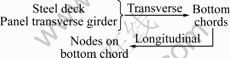
The orthotropic integral steel deck has merit of good integrity, in which the steel deck is welded with bottom chords of main trusses. The support system of the steel deck can be either longitudinal and transverse girder system or dense transverse girder system with many slender panel transverse girders besides node transverse girders. Because of more reasonable mechanical behavior, the dense transverse girder system has got more application [9-10]. The concrete slab is mainly used to carry ballast, which is composited with integral steel floor system not with the main trusses. The orthotropic integral steel deck-concrete slab composite deck is applied in ?resund Railcum-Road Bridge, NDB and Zhengzhou Yellow River Railcum-Road Bridge [1, 8, 11-12].
In the orthotropic integral steel deck structure, the integral steel deck and its support system both participate in the whole deformation of the main trusses. The deck loads are transmitted to the main truss nodes mainly through two routes [12]:
Rout I (R1):

Rout II (R2):
According to R2, in the transversal transmission of deck loads, vertical bending of node transverse is decreased with the participation of steel deck and panel transverse girders. On the other side, because of good integrity of the composite deck, the out-of-plane bending of transverse girders caused by ��The first mechanical system action�� is also reduced greatly. Compared with the steel longitudinal and transverse girders-concrete slab composite deck, stress state of transverse girders in the orthotropic integral steel deck-concrete slab composite deck has been improved greatly and become more reasonable.
In particular, the loads transmitted transversally through the steel deck and panel transverse girders produce vertical bending on the main truss bottom chords. Namely, the bottom chords bear the combined action of axial force and vertical bending, the stress state of which has more disadvantage than that of the steel longitudinal and transverse girders-concrete slab composite deck. Therefore, the main truss bottom chords of the orthotropic integral steel deck-concrete slab composite deck are usually designed with strong section.
Because of the densely arranged longitudinal and transverse girders in the steel floor system, the distance between the girders on the steel deck is quite small, either longitudinally or transversally. Thus, the steel deck takes little part in ��The second mechanical system action�� and ��The third mechanical system action��.
3 Stud design methods for steel longitudinal and transverse girders-concrete slab composite deck
3.1 Stud design methods for longitudinal girder
According to the above analysis of the steel longitudinal and transverse girder-concrete slab composite deck, it should be recognized that there exists longitudinal shear force Ql between the steel longitudinal girder and the concrete slab with the action of deck loads:
Ql=Ql1+Ql2 (1)
where Ql1 is the shear force between the steel longitudinal girder and the concrete slab caused by longitudinal force Nf of composite floor system shared from ��The first mechanical system action��, which is transmitted from the steel longitudinal girder to the concrete slab completely by the studs on the interface; Ql2 is the shear force between the steel longitudinal girder and the concrete slab caused by ��The second mechanical system action�� under vertical deck loads.
3.1.1 Calculation of Ql1 and stud arrangement
For the steel longitudinal and transverse girder- concrete slab composite deck, the longitudinal girder can be regarded as being simply supported on the transverse girder approximately. In the range of panel length d, axial force Nl borne by the steel longitudinal girder would remain uniform along the length of girder. However, influenced by the boundary condition of the girder end, Nl presents the obvious curve in the range of 0.2d near the girder ends [13], then becomes evenly distributed with the transition to the middle part (see Fig.1).
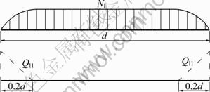
Fig.1 Distribution of Ql1 on interface of steel girder and slab in range of d
The change rate of Nl in range of 0.2d near each girder end, dNl/dx, is reflected as the longitudinal shear force, Ql1, on the interface of concrete slab and steel girder, which is borne by the studs in the 0.2d sector. Therefore, in the range of 0.2d near each girder end, the shear force of a single stud ql1 is
![]() (2)
(2)
In Eq.(2), nl1 is the sum of studs arranged on the top flange of longitudinal girder in 0.2d sector. In the middle sector, Ql1 is zero, and the studs should be arranged in accordance with requirements.
3.1.2 Calculation of Ql2 and stud arrangement
The distribution of Ql2 on the interface is similar to that of the vertical shear force of longitudinal girder (see Fig.2). In the range of d, the shear force of a single stud on the interface should be calculated in subsection in accordance with the distribution of Ql2. According to the shear force reciprocal theorem, there is
![]() (3)
(3)
where Qv is the vertical shear force of the steel longitudinal girder-concrete slab composite girder, and takes the maximum value of each subsection; Sl is the area moment of the transformed concrete area (transform to steel ) to the neutral axis of the composite girder; Il is the moment of inertial of the transformed composite girder; li is the length of each shear force sector, which should not be less than 0.1d near the girder ends [14-15].

Fig.2 Distribution of Ql2 on interface of steel girder and slab in range of d
In the range of li, studs can be arranged with equal distance. The shear force of a single stud is
![]() (4)
(4)
where nl2 is the sum of studs arranged in the length of li.
For studs on either end of the longitudinal girder in the panel, there is
ql=ql1+ql2<[q]
or
?q1=?ql1+?ql2<[?q] (5)
where [q] is the designed bearing capacity of a single stud; [?q] is the designed fatigue bearing capacity of a single stud; ?ql is the shear force amplitude of a single stud on the interface of either end of the longitudinal girder under live load.
3.2 Studs design methods for transverse girder
Because the transverse girders of steel longitudinal and transverse girders-concrete slab composite deck are in compound bending state, there exist both longitudinal shear force Qh1 and transversal shear force Qh2 on the interface of concrete slab and steel transverse girder. Thereinto, Qh1 is caused by the out-of-plane bending of the transverse girder with ��The first mechanical system action��, and Qh2 is caused by the vertical bending of the transverse girder with ��The second mechanical system action��. With the co-action of Qh1 and Qh2, the calculation of the shear forces of a single stud on the interface qh1 and qh2 is similar to that of ql2, namely, the sectional calculation is done in accordance with the distribution of Qh1 and Qh2. Due to the orthogonality of Qh1 and Qh2 in the horizontal plane, there is
![]()
or
![]() (6)
(6)
4 Stud design methods for orthotropic integral steel deck-concrete slab composite deck
The stud design methods for the orthotropic integral steel deck-concrete slab composite deck are as follows.
1) With the action of deck loads, the steel longitudinal girders suffer the coactions of longitudinal force and vertical bending. The former is caused by ��The first mechanical system action�� and the latter is caused by the deck loads. Therefore, design and calculation of studs on the interface are similar with the methods presented in Section 3.1.
2) Due to the great improvement of the out-of-plane deformation, the transverse girders mainly suffer vertical bending under the deck loads while the out-of-plane bending can be neglected, especially for the orthotropic integral steel deck-concrete slab composite deck with dense transverse girders arranged [12]. Consequently, the design and calculation of studs on the interface of the steel transverse girder and concrete slab are similar to the methods presented in Section 3.1.2.
3) The studs on the orthotropic integral steel deck can be arranged according to the requirements.
5 Design and calculation of studs on composite deck of NDB
5.1 Overview of bridge
Nanjing Dashengguan Yangtze River Bridge (NDB) in Beijing-Shanghai high-speed railway is a continuous through steel truss (arch) bridge with three main trusses (arches) and six rail lines. The main bridge is a six-span continuous steel truss (arch) structure of (108+192+336+ 336+192+108) m, and the side bridges in shallow waters are two continuous steel truss structures with a span of (2��84) m [11-12]. The width of the deck is (5.2+15+15+ 5.2) m, with two lines of I-type railway in width of 15 m on the upstream side, two lines of high speed railway in width of 15 m on the downstream side, and urban light rail on each 5.2 m wide side. The design speed of high speed railway is 300 km/h.
The orthotropic integral steel deck-concrete slab composite deck supported by densely arranged transverse girder system was adopted by NDB. The orthotropic steel deck was welded with the main truss bottom chords. Along the bridge, one node transverse girder and three panel transverse girders were set in each panel. Multiple U-type ribs were designed on the steel deck transversally. There were two converse T-type longitudinal girders under every railway line (see Fig.3). C40 cast-in-place concrete ballast slab was set on the orthotropic steel deck, which was composited with steel deck, longitudinal girders and transverse girders by studs (��19 mm �� 100 mm) (see Fig.4).

Fig.3 Main truss and bridge deck of Nanjing Dashengguan Yangtze River Bridge

Fig.4 Standard cross section of ballast bed of Nanjing Dashengguan Yangtze River Bridge (Unit: cm)
5.2 Main points of studs design and calculation
5.2.1 Calculation of Ql1 on longitudinal girder
Under ��The first mechanical system action��, the total axial force of floor system and bottom chords is
N=Nb+Nf
where Nb is the axial force of bottom chords, and Nf is the axial force of floor system shared.
An equivalent steel floor system consists of steel longitudinal girders, longitudinal U-type ribs, steel deck and transformed concrete slab (transform concrete slab into steel according to the elastic modulus ratio of steel to concrete). Calculate Nf according to Ref.[12], and distribute it to the transformed concrete slab and steel floor system in accordance with area ratio, then there is
 (7)
(7)
where ![]() is the longitudinal force shared by the steel floor system,
is the longitudinal force shared by the steel floor system, ![]() is the longitudinal force shared by the concrete ballast slab, Ac is the area of the transformed concrete slab (into steel), and As is the area of the steel floor system.
is the longitudinal force shared by the concrete ballast slab, Ac is the area of the transformed concrete slab (into steel), and As is the area of the steel floor system.
5.2.2 Simplified calculation model of Ql2 on longitudinal girder
Ql2 is caused by the vertical shear force of the longitudinal girders with the action of deck loads, which can be calculated by the following simplified model.
Take a panel from one side of two railway lines for example (see Fig.5). If the total deck load in a single panel is qt, allocate qt equally to the four longitudinal girders, then each longitudinal girder bears deck load of qt/4 distributed uniformly. In calculation, the longitudinal girder of d/4 long between two adjacent transverse girders is regarded as simple supported girder, and the concrete slab is divided to four longitudinal girders transversely equally. The steel deck is neglected, then a simplified calculation model of longitudinal girder is illustrated in Fig.6. The corresponding shear force distribution can be got in terms of calculation methods of general composite girder, as shown in Fig.6.

Fig.5 Single panel of Nanjing Dashenguan Yangtze River Bridge (double railway lines)

Fig.6 Simplified calculation model of longitudinal beam: (a) Simplified longitudinal girder; (b) Shear force distribution
According to Fig.6, the longitudinal shear force Ql2 on the interface of segment li is
![]() (8)
(8)
where �� is the shear stress of shear force segments; li is the length of shear force segment; Qv is the vertical shear force of the simplified longitudinal girder, and takes the maximum value of each segment; S is the area moment of the transformed concrete slab to the neutral axis of the simplified longitudinal girder; Il is the transformed inertial moment of the simplified longitudinal girder.
5.2.3 Simplified calculation model of Qh1 on transverse girder
Transversal shear force Qh1 exists on the interface of concrete slab and steel transverse girder because of the vertical bending under the deck loads. Taking the panel in Fig.5 for example, each transverse girder, at node or between nodes, can be regarded as being simply supported on the two main trusses. According to the ratio of 1:1, the concrete slab is divided equally to the two adjacent transverse girders, then the simplified calculation model of studs on the transverse girder is similar to that illustrated in Fig.6.
The mechanical performance analysis of the whole bridge [12] has demonstrated that every node transverse girder suffers 0.4qt, which is transmitted from the longitudinal girders in the neighbor two panels. Every panel transverse girder suffers 0.2qt, which is transmitted from each panel transverse girder to the longitudinal girders. Then, Qh1 can be calculated as same as Qh2.
5.2.4 Design capacity and requirements of studs
Take the revising of ��Design Rules of Railway Composite Bridge�� (China), Ref.[12] and relevant research achievement [13-16] can be used as the reference of stud design bearing capacity. According to Ref.[12], for ��19 mm stud in compressed concrete, designed bearing capacity is [q]=34 kN, and designed fatigue bearing capacity is [?q]=17 kN; corresponding values of [q] and [?q] should be multiplied by a discount of 0.85 for ��19 mm stud in tensile concrete.
The requirements of the studs arrangement can also take the relevant rules in Refs.[12, 16-17].
5.3 Studs design and arrangement of NDB
The deck loads of NDB are as follows.
1) Second stage dead load (D2): includes the self weight of ballast, concrete ballast slab and rails, distributed uniformly in the range of concrete ballast slab, D2=396 kN/m;
2) Live load (L): 80 kN/m for a single I-type railway line, 64 kN/m for a single high speed railway, taking a discount of 0.75 for full bridge distribution of four lines; 28.5 kN/m for a sing light rail, no discount, full bridge distribution of two lines.
According to the methods put forward, taking a middle panel in 336 m arch truss span of NDB for example, the arrangement of the studs on steel longitudinal girders and transverse girders can be got through the calculation with the action of D2 and L, respectively. For the sake of safety, check calculation of stud fatigue capacity is carried out in accordance with the arrangement. The results show that the shear force per stud is less than the designed fatigue capacity with enough safety reserved, including studs on panel transverse girders, node transverse girder and longitudinal girders, as listed in Table 1.
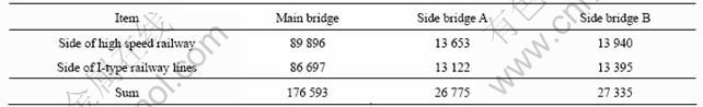
According to the calculation results, the studs of NDB are arranged with a spacing of 40 cm��40 cm on the steel deck, the transversal spacing is shortened to 20 cm underneath the ballast barricade, and the longitudinal spacing is reduced to 25 cm at the end of the longitudinal girders. The sum of studs used for NDB is 230 703, as listed in Table 2.
Table 1 Fatigue calculation results of ��19 mm studs on steel longitudinal beams and transverse beams of middle panel of 336 arch truss span of Nanjing Dashengguan Yangtze River Bridge
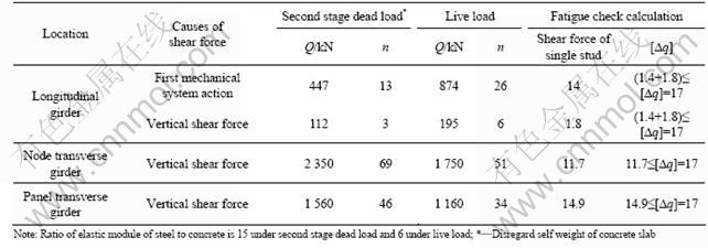
Table 2 Sum of ��19 studs of Nanjing Dashengguan Yangtze River Bridge
6 Conclusions
1) Under deck loads, the longitudinal girders in the composite floor system of through steel bridges are in tension-bending state with the combined action of longitudinal force and vertical bending. The former is caused by ��The first mechanical system action��, and the latter is caused by vertical deck loads. The longitudinal shear force on the interface of steel longitudinal girder and concrete slab is caused by the co-action of the above mentioned two parts. In the range of 0.2d segment on each end of the panel, the studs can be arranged uniformly according to the longitudinal shear force.
2) The transverse girders in the steel longitudinal and transverse girders-concrete slab composite deck are in compound bending state. The out-of-plane bending of transverse girders has to be taken into account in bridge design. Under deck loads, the shear force on the interface of the concrete slab and steel transverse girder consists of two parts: one is the transversal shear force caused by the vertical bending, and the other is longitudinal shear force caused by the out-of-plane bending.
3) The out-of-bending of the transverse girders in the orthotropic integral steel deck-concrete slab composite deck is small enough to be neglected. Thus, the stud design of transverse girders only needs to take the shear force caused by the vertical bending into account. Due to the dense arrangement of longitudinal and transverse girders on the steel floor system, the distance between the girders is quite small so that the steel deck participates little in ��The second mechanical system action�� and ��The third mechanical system action��. Therefore, the studs on the orthotropic integral steel deck can be arranged according to the requirements.
4) On the basis of the above methods, combined with the structural characteristics of the composite deck of NDB, simplified stud calculation models are proposed for the longitudinal girders and transverse girders, respectively. The results of the example show that, by arranging the studs in accordance with the methods put forward, the shear force of a single stud is quite less than the design bearing capacity with a certain safety reserved. The proposed method is simple and applicable, which has been successfully applied in real bridges.
References
[1] HOU Wen-qi. Study of railway steel-concrete composite bridges and shear connectors [D]. Changsha: School of Civil and Architectural Engineering, Central South University, 2009. (in Chinese)
[2] ZHANG Ye-zhi. Comparison of bridge structures of railway through truss composite bridges [J]. Journal of the China Railway Society, 2005, 27(5): 107-110. (in Chinese)
[3] VALENTE I, CRUZ P J S. Experimental analysis of Perfobond shear connection between steel and lightweight concrete [J]. Journal of Constructional Steel Research, 2004, 60: 465-479.
[4] NAM Jeong-Hun, YOON Soon-Jong, OK Dong-Min, SHO Sun-Kyu. Perforated FRP shear connector for the FRP-concrete composite bridge deck [J]. Key Engineering Materials, 2007, 334/335: 381-384.
[5] ZHOU De, YE Mei-xin, LUO Ru-deng. Improved methods for decreasing stresses of concrete slab of large-span through tied-arch composite bridge [J]. Journal of Central South University of Technology, 2010, 17(3): 648-652.
[6] HUANG Qiong, YE Mei-xin, WU Qin-qin. Analysis of steel-concrete composite structure with overlap slab of Xingguang Bridge [J]. Journal of Central South University of Technology, 2007, 14(1): 120-124.
[7] GIMSING N J. The ?resund technical publications: The BRIDGE [M]. ?resundsbro Konsortier: Repro & Teryk, 2000: 147-148.
[8] HOU Wen-qi, YE Mei-xin. Experiments on the mechanical characteristic of the integral steel orthotropic bridge deck with three main trusses of Nanjing Dashengguan Yangtze River Bridge [J]. Journal of Railway Science and Engineering, 2008, 5(3): 11-17. (in Chinese)
[9] CHEN Yu-ji, YE Mei-xin. Force of through plate-truss composite beam on high-speed railway [J]. Journal of Central South University: Science and Technology, 2004, 35(5): 849-854. (in Chinese)
[10] CHEN Yu-ji, YE Mei-xin. Model test for through truss composite beam with simple support [J]. China Railway Science, 2004, 25(6): 82-87. (in Chinese)
[11] YI Lun-xiong. Engineering characteristic and key technique of Dashengguan Changjiang River Bridge [J]. Steel Structure, 2007(5): 78-80. (in Chinese)
[12] YE Mei-xin, HOU Wen-qi. Study on the key technique of Dashengguan Changjiang River Bridge in Nanjing��Study report on analysis and test for ballast integral deck [R]. Changsha: Central South University, 2006. (in Chinese)
[13] ZHU Pin-ru. Design principles of steel-concrete composite beam [M]. 2nd ed. Beijing: China Architecture and Building Press, 2006: 157-167. (in Chinese)
[14] British Standards Institution. Code of practice for design of composite bridges [S]. BS5400: Part 5. 1979.
[15] JOHNSON R P. Composite structures of steel and concrete-beams, slabs, columns and frames of buildings [M]. 3rd ed. Blackwell Publishing, 2004: 27-29.
[16] YE Mei-xin, ZHANG Ye-zhi, HOU Wen-qi. Experimental study on the steel truss-concrete slab composite girder of Wuhu Yangtze River Bridge [R]. Changsha: Changsha Railway institution, 1999. (in Chinese)
[17] ANDERSON N S, MEINHEIT D F. A review of headed-stud design criteria in the sixth edition of the PCI Design Handbook [J]. PCI Journal, 2007(1/2): 2-20.
(Edited by YANG Bing)
Foundation item: Project(2004G016-B) supported by the Science and Technology Development Program of Railways Department, China
Received date: 2010-10-30; Accepted date: 2011-01-06
Corresponding author: HOU Wen-qi, PhD; Tel: +86-13507319845; E-mail: 40951515@qq.com

