
Phase-field simulations of forced flow effect on dendritic growth perpendicular to flow
WANG Zhi-ping1, 2, WANG Jun-wei1, ZHU Chang-sheng1, 3, FENG Li1, XIAO Rong-zhen1
1. State Key Laboratory of Gansu Advanced Non-ferrous Metal Materials,Lanzhou University of Technology, Lanzhou 730050, China;
2. Research Center of Gansu Non-ferrous Metal Materials and Composite Materials Engineering,Lanzhou 730050, China;
3. Computer Aided Designed Center, Lanzhou University of Technology, Lanzhou 730050, China
Received 6 April 2010; accepted 1 July 2010
Abstract: The effect of supercooled melt forced laminar flow at low Reynolds Number on dendritic growth perpendicular to melt flow direction was investigated with the phase-field method by incorporating melt convection and thermal noise under non-isothermal condition. By taking the dendritic growth of high pure succinonitrile (SCN) supercooled melt as an example, side-branching shape difference of melts with flow and without flow was analyzed. Relationships among supercooled melt inflow velocity, deflexion angle of dendritic arm and dendritic tip growth velocity were studied. Results show that the melt inflow velocity has few effects on the dendritic tip growth velocity. A formula of relationship between the velocity of the melt in front of primary dendritic tip and the dendritic growth time was deduced, and the calculated result was in quantitative agreement with the simulation result.
Key words: phase-field method; laminar flow; dendritic growth; computer simulation; solidification; flow velocity
1 Introduction
There are not only natural convection, but also forced flow because of external force filed during the process of material solidification[1]. BECKERMANN et al[2], TONG et al[3-4], JEONG et al[5] and BOETTINGER et al[6] have used phase-field method (PFM), incorporating phase-field control equation and flow equations which were solved numerically using algorithm SIMPLE method, for investigating the effect of convection upon microstructure during solidification process. Although the PFM has been widely used to simulate the solidification microstructure of pure material and multicomponent alloy in two[7-9] and three dimensions[10], but the study coupling with convection started relatively late, ZHU et al[11] simulated and studied both single-crystal and multi-crystal growth processes in a forced flow melt using a coupled MCA model with propagation. CHEN et al[12-13] have simulated the effect of forced flow on pure material dendritic solidification and studied the relationship between growth velocity of dendritic tip and flow velocity of supercooled melt using the model coupled flow equations with PFM control equation[4], and the flow equations were solved by SIMPLE algorithm too. LONG et al[14] have studied the effect of forced flow on binary alloy solidification process.
Above researchers all paid main attention to the relationship between the flow velocity of supercooled melt and the asymmetry of dendritic shape of the upstream and downstream arm. However, dendritic growth perpendicular to flow was not studied incisively when the supercooled melt had forced flow, such as relationships between the inflow velocity of supercooled melt and the deflexion angle of primary dendritic arm, growth velocity of dendrite tip and flow velocity in front of primary dendritic arm perpendicular to the flow. Consequently, based on TONG et al[4] model coupled phase-filed control equation and flow equation, the effect of supercooled melt forced flow on the side-branching, deflexion angle of primary dendritic arm and tip growth velocity was studied. At last, the relationship between dendritic growth time and melt flow velocity in front of primary dendritic tip was investigated.
2 Mathematical model
2.1 Phase-filed control equation
Phase-field variables,  =-1 and =+1, refer to the bulk liquid and solid phases, respectively. The pure material phase-filed control equation with anisotropic surface energy of KARMA and RAPPEL[15] is written as follows:
 (1)
(1)
where τ(n) and w(n) are relaxation time and the interface thickness, respectively, and they are all the functions of the interfacial normal n in order to account for anisotropic surface energy and kinetics with anisotropic parameters: 
 and as(n)
  where ε is the anisotropy strength of the surface energy, τ0=1 and w0=1 are the scales of time and length, respectively); u is dimensionless temperature:
  , where T is the dimensional temperature of bulk liquid and Tm is the dimensional melting temperature; L and cp are the latent and specific heat, respectively; λ is coupling constant of temperature and phase-filed:
  , where d0 is the capillary length and a1=0.883 9 in Eq.(1).
2.2 Energy conservation equation coupled with flow
The conserved bulk noise is added to the energy conservation equation of pure material coupled with melt flow in following manner:
 (2)
(2)
where ψ can be viewed as a solid fraction:  ,
,  ; the bulk solid can be assumed to be rigid, and it is simply assigned a velocity of zero and the bulk liquid velocity is
 (3)
(3)
where U0x and U0y are the dimensional variables of melt inflow velocity along directions x and y, respectively, their dimensionless forms are: U0xd0/D→Ux, U0yd0/D→ Uy. The dimensional thermal diffusivity is denoted by D and cast into dimensionless form as  ; The noise cited from Ref.[4], q stands for the thermal noise vector and obeys a Gaussian distribution as
 (4)
(4)
where Fu is the magnitude of the thermal noise and Fu=10-3; δmn is random variable; δ is the delta function; r and r′ are position vector; t and t′ are time variables.
2.3 Conservation equations for mass and momentum
Assume that there is density difference between solid and liquid and the viscous force is constant. In two dimensions, the conservation equations for mass and momentum of viscous incompressible flow are Eqs.(5) and (6), respectively:
 (5)
(5)
 (6)
(6)
where p is pressure; ν is kinematics viscosity; and ρ is density of liquid.
3 Numerical issues
3.1 Mesh generation and time step
The flow equations are solved numerically using Sola algorithm which is erected by self-adaptive pressure iteration method and staggered grid is used. We choose a uniform spacing of Δx=Δy=0.800w0 as a matter of convenience computation numerically; and the control volumes of pressure and phase filed at the centre of the grid are Ux and at the boundary of east and north of grid, Uy. Pressure does not need boundary condition.
3.2 Initial condition and boundary condition
Assume that the simulation domain is an infinitely long passage with fixed upside and underside boundary. Supercooled melt enters the domain from left boundary with a uniform velocity Ux, and exits at the left boundary. In order to calculate numerically, part of the passage chosen is shown in Fig.1. An initial hemisphere nucleus with diameter 2R is at the middle of underside of simulation domain:
 (7)
(7)
By assuming the slip condition at upside and underside boundary and the no-slip condition at a sharp solid-liquid interface, the Zero-Newman condition is used in phase-filed and temperature filed, while thermal radiation is ignored, and the boundary conditions of
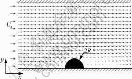
Fig.1 Initial and boundary conditions of simulation domain
phase-filed and temperature field are
 (8)
(8)
3.3 Computational parameters
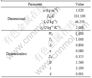
Assume that the liquid and solid have the same density ρ and the same diffusivity D. A comparatively higher dimensionless supercooling Δ and larger anisotropy strength ε of the surface energy are used. The simulation domain is 500Δx×400Δy. The parameters of pure SCN and computational parameters are listed in Table 1.
Table 1 Material parameters of pure SCN and computational parameters
4 Results and discussion
4.1 Effect of melt forced flow on side-branching
Figs.2(a) and (b) show the phase-filed and temperature―velocity filed, respectively, while the melt inflow velocity is Ux=0 and dendrite growth time is t= 5 100Δt. Correspondingly, when the melt inflow velocity is 0.10, at the same growth time the phase-filed and temperature―velocity filed are shown in Figs.2(c)and (d) respectively. It can be seen from Figs.2(b) and (d) that the temperature boundary layer thickness in upstream is not only thinner than that in downstream in the case of convection (Ux=0.10), but also thinner than that in the case of no convection (Ux=0). Furthermore, flow velocity in the upstream side near dendritic is higher than that in the downstream side because arrowhead length which notes the value of fluid flow velocity in upstream is longer than that in downstream.
By the theory of fluid mechanics, no matter how high flow velocity is, a laminar boundary layer (its thickness is δ) always exists in liquid side of solid-liquid boundary. δ can be expressed as
 (9)
(9)
where τ is flow internal friction of fluid and defined as
 (10)
(10)
Taking Eq.(9) together with Eq.(10), we obtain
 (11)
(11)
Eq.(11) shows that the liquid flow velocity is in inverse proportion to δ. In addition, the temperature gradient in front of the solid-liquid phase interface is in inverse proportion to δ too. So, the thickness of temperature boundary layer in upstream is thinner than that in downstream or in the case of no convection (Ux=0). Simulation results agree well with the theoretical analysis results.
A lot of tubercles induced by thermal noise are formed on the solid-fluid phase boundary and extend into supercooled melt. By comparing Fig.2(c) with Fig.2(a), in the case of convection, we can find that the secondary dendritic arm in upstream is more developed, it looks like shred and the spacing between of them becomes small; moreover, higher side-branching dendritic does not appear. This is because the thickness of temper boundary layer in upstream is thinner than that in downstream or in the case of no convection, which has been proved previously in this part. The tubercles in upstream easier evolve secondary dendritic arm and grow competitively. However, in downstream, the thickness of temper boundary layer is thicker and the tubercles will be melted as soon as it formed. As a result, there is no side-branching appearing distinctly.
4.2 Deflexion effect of melt force flow on primary dendritic arm
Fig.3 shows growth trajectories of dendritic tip and fitting captives of them at different inflow velocities. Grid points of the dendritic tip are denoted by coordinates, variable x and f(x) instead of grid point
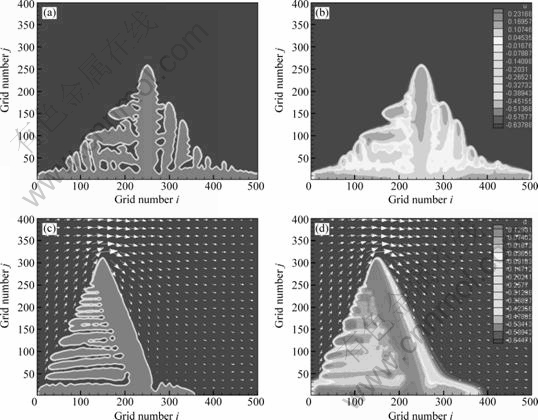
Fig.2 Phase-filed (a, c) and temperature-velocity filed (b, d) at Ux=0 and Ux=0.10 and t=5 100Δt: (a), (b) Ux=0; (c), (d) Ux=0.10
variable i and j respectively to express expediently. Fitting curves of dendritic tip growth trajectory are f0.1(x), f0.15(x), f0.2(x) and f0.25(x), while the melt inflow velocity Ux values are 0.10, 0.15, 0.20 and 0.25, respectively:
 (12)
(12)
The growth trajectory is almost linear at every inflow velocity. Fig.4 shows the deflexion angle α and longitudinal section width of fluid flow through. α is deflexion angle between primary dendritic arm perpendicular to flow while melt with convection and without convection. For different melt inflow velocities, α values are different. The relationship between α and k (k is slope of tip growth trajectory fitting curve) is defined as
 (13)
(13)
As revealed in Fig. 5, the relationship between liquid inflow velocity Ux and α is obtained by combining Eq.(12) and Eq.(13). With a comparatively low inflow velocity (0-0.1), α increases sharply. However, α
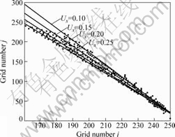
Fig.3 Growth trajectories of dendritic tip at different flow velocities and fitting captives
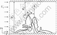
Fig.4 Deflexion angle α and longitudinal section width of fluid flow through
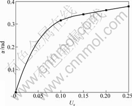
Fig.5 Relationship between deflexion angle α and fluid inflow velocity Ux
increases comparatively slowly while the dimensionless inflow rate increases from 0.1 to 0.25.
4.3 Growth velocity effect of melt forced flow on primary dendritic tip
Fig.6 shows a relationship between the dimensionless growth velocity (Vtip=Vd0/D) of primary dendritic tip perpendicular to flow and the dendritic growth time t at different inflow velocities (Ux), where V is dimensional growth velocity. The dendrite tip growth velocity with convection (Ux )is not only higher than that without convection (Ux=0), but it increases continually slowly at any velocity. Furthermore, and growth velocity does not reach absolutely steady state, which is caused by the continually increasing flow velocity in front of primary dendritic tip. The flow velocity in front of primary dendritic tip at different time is illustrated in Fig.7 at Ux=0.25.
Fig.6 also shows that with the increase of flow rate, the growth speed of dendritic tip becomes high. But the
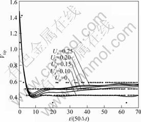
Fig.6 Growth velocity of dendritic tip perpendicular to flow with different time t at different melt inflow speeds Ux
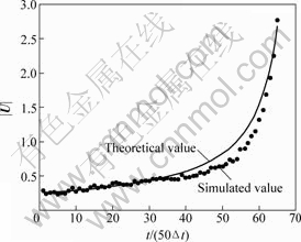
Fig.7 Relationship between melt flow velocity |U| in front of dendritic tip and dendritic growth time t when Ux=0.25
inflow rate has a minimal impact on the growth speed. At the time of t=60×50Δt, dendritic tip growth dimensionless speed is 0.50 and liquid dimensionless inflow rate is 0.1, growth speed is 0.55 while inflow rate is 0.25. The growth speed only increases by 16% while the liquid inflow rate increases by 150%. It is convinced that the difference of supercooled melt inflow velocity has very little effect on the growth velocity of dendritic tip perpendicular to flow.
4.4 Relationship between melt flow velocity in front of dendritic tip and solidification time
W2 is gap width between primary dendritic tip and side boundary, it is increasingly smaller with the growth of dendritic tip. If product of cross section area S (S=1×W2) and flow velocity (|U|) is constant number a (a ≥0) for continuous incompressible fluid, we get the form easily:
 (14)
(14)
Based on the analysis of Section 3.3 in this paper, the supercooled melt flow has a faint effect on dendritic growth velocity. So, we neglect growth velocity change which is caused by the change of flow velocity in front of dendritic tip. Consequently, at a given melt infow velocity and other constant variables,a relationship between dendritic growth time (t) and the primary dendritic tip dimensionless growth velocity (Vtip) is shown as
 (15)
(15)
where W1 is the inlet mass flow width. By combining Eq.(14) with Eq.(15), we derived the relationship between melt flow velocity |U| in front of dendritic perpendicular to flow and growth time t:
 (16)
(16)
Fig.7 shows relation curve of Eq.(16) when Ux=0.25, a=50, W1=200, Vtip=0.5 and a=0.377 rad and simulated results under the same condition. It indicates that the simulated results and the theoretical results are in agreement.
5 Conclusions
1) The secondary dendritic arm in upstream looks like shred and the spacing of them becomes small for the melt with flow. However, side-branching does not appear distinctly in downstream.
2) There is a tendency that primary dendritic arm growth is perpendicular to flow in upstream. With the increase of the inflow rate at low Reynolds number, the deflexion angle α becomes big too. α increases more quickly at a comparatively low velocity than at a high velocity.
3) In the case of the undercooled melt has force flow, the growth velocity of the dendritic tip perpendicular to the flow is higher than that without flow; however, the melt inflow velocity has few effect on the dendritic tip growth velocity.
4) Flow velocity (|U|) of undercooled melt in front of primary dendritic tip perpendicular to flow increases with the dendritic growth time (t) increasing, and there is
relationship: ; and the simulated results agree well with the results of theoretical analysis.
References
[1] SUN Y, BECKERMANN C. Effect of solid-liquid densith change on dendritic tip velocity and shape selection [J]. Journal of Crystal Growth, 2009, 311(4): 4447-4453.
[2] BECKERMANN C, DIEPERS H J, STEINBACH I, KARMA A, TONG X. Modeling melt convection in phase-field simulations of solidification [J]. Journal of Computational Physics, 1999, 154: 468-496.
[3] TONG X, BECKERMANN C, KARMA A. Velocity and shape selection of dentritic crystals in a forced flow [J]. Phys Rev E, 2000, 61(1): 49-53.
[4] TONG X, BECKERMANN C, KARMA A, LI Q. Phase-filed simulations of dendritic crystal growth in forced flow [J]. Phys Rev E, 2001, 63(6): 1-16.
[5] JEONG J H, DANTZIG J A, GOLDENFELD N. Dendritic growth with fluid flow in pure materials [J]. Metallurgical and Material Transaction A, 2003, 34(3): 459-466.
[6] BOETTINGER W J, WARREN J A, BECKERMANN C, KARMA A. Phase-field simulation of solidification [J]. Annual Review of Material Research, 2002, 32: 163-194.
[7] LONG Wen-yuan, CAI Qi-zhou, CHEN Li-liang, WEI Bo-kang. Phase-field simulations of solidification of Al-Cu binary alloys [J]. Transactions of Nonferrous Metals Society of China, 2004, 14(2): 291-296.
[8] ZHU Chang-sheng, WANG Zhi-ping, JING Tao, XIAO Rong-zhen. Parameters affecting microsegregation in phase-field simulation [J]. Transactions of Nonferrous Metals Society of China, 2006, 16(4): 760-765.
[9] ZHU Yao-chan, YANG Gen-cang, WANG Jin-cheng, ZHAO Da-wen. Investigation on stability of directionally solidified CBr4-C2Cl6 lamellar eutectic by using multiphase field simulation [J]. Chinese Physics, 2007, 16(3): 805-811.
[10] ZHU Chang-sheng, XIAO Rong-zhen, WANG Zhi-ping, FENG Li. Numerical simulation of recalescence of 3-dimensional isothermal solidification for binary alloy using phase-field approach[J]. Transactions of Nonferrous Metals Society of China, 2009, 19(6): 1286-1293.
[11] ZHU Ming-fang, DAI Ting, LI Cheng-yun, HONG Jun-shao. Numerically simulation the dendritic growth process under forced flow[J]. Science in China E, 2005, 35(7): 673-687. (in Chinese)
[12] WANG Ying-shuo, CHEN Chang-le. Phase field simulation of pure material dendritic growth under convection condition [J]. Foundry, 2008, 57(3): 249-258. (in Chinese)
[13] CHEN Yu-juan, CHEN Chang-le, Simulation of the influence of convection velocity on up stream dendritic growth using pha se-field method [J]. Acta Phys Sin, 2008, 57(7): 4585-4589. (in Chinese)
[14] LONG Wen-yuan, L? Dong-lan, XIA Chun, PAN Mei-man, CAI Qi-zhou, CHENG Li-liang. Phase-field simulation of non-isothermal solidification dendritic growth of binary alloy under the force flow[J]. Acta Phys Sin, 2009, 58(11): 7802-7808. (in Chinese)
[15] KARMA A, RAPPEL W J. Phase-field method for computationally efficient modeling of solidification with arbitrary interface kinetics [J]. Phys Rev E, 1996, 53(4): R3017-R3020. (in Chinese)
相场法模拟强迫层流对流动法向枝晶的影响
王智平1, 2,王军伟1,朱昌盛1, 3,冯 力1,肖荣振1
1. 兰州理工大学 甘肃省有色金属新材料省部共建重点实验室,兰州 730050;
2. 甘肃省有色金属及复合材料工程研究中心,兰州 730050;
3. 兰州理工大学 CAD中心,兰州 730050
摘 要:采用耦和流场的相场模型,考虑热扰动影响因素,模拟非等温条件下低雷诺数过冷熔体强迫层流对流动法向枝晶生长的影响。以高纯丁二腈(SCN)过冷熔体枝晶生长为例,分析熔体有流动和无流动时二次枝晶形貌差异的原因;研究过冷熔体层流速度、流动法向一次枝晶臂偏转角度和枝晶尖端生长速度之间的关系;推导枝晶尖端前沿熔体流动速度值与枝晶生长时间的理论表达式;定量对比其理论值与模拟值,结果吻合较好。
关键词:相场法;层流;枝晶生长;计算机模拟;凝固;流动速度
(Edited by YANG Hua)
Foundation item: Project (10964004) supported by the National Natural Science Foundation of China; Project (096RJZA104) supported by the Natural Science Foundation of Gansu Province, China
Corresponding author: WANG Jun-wei; Tel: +86-13619331460; E-mail: wtj3318@163.com
DOI: 10.1016/S1003-6326(11)60758-9

