
Phase-field simulation of forced flow effect on random preferred growth direction of multiple grains
WANG Jun-wei1, ZHU Chang-sheng1, 2, WANG Zhi-ping1, 3, FENG Li1, XIAO Rong-zhen1
1. State Key Laboratory of Gansu Advanced Non-ferrous Metal Materials,
Lanzhou University of Technology, Lanzhou 730050, China;
2. Computer Aided Designed Center, Lanzhou University of Technology, Lanzhou 730050, China;
3. Research Center of Gansu Non-ferrous Metal Materials and
Composite Materials Engineering, Lanzhou 730050, China
Received 30 July 2010; accepted 5 November 2010
Abstract: The random distribution problem of dendrite preferred growth direction was settled by random grid method. This method was used to study the influence of forced laminar flow effect on multiple grains during solidification. Taking high pure succinonitrile (SCN) undercooled melt as an example, the forced laminar flow effect on multiple grains was studied by phase-field model of single grain which coupled with flow equations at non-isothermal condition. The simulation results show that the random grid method can reasonably settle the problem of random distribution and is more effective. When the solid fraction is relatively low, melt particles flow around the downstream side of dendrite, and the flow velocity between two dendrite arms becomes high. At the stage of solidification time less than 1800��t, every dendrite grows freely; the upstream dendrites are stronger than the downstream ones. The higher the melt flow rate, the higher the solid fraction. However, when the solid fraction is relatively high, the dendrite arm intertwins and only a little residual melt which is not encapsulated can flow; the solid fraction will gradually tend to equal to solid fraction of melt without flow.
Key words: phase-field method; multiple grains; laminar flow; preferred growth direction; computer simulation; solidification; flow velocity
1 Introduction
Quality and service performance of casting are determined by microstructure which is formed during solidification process of casting [1]. Forced laminar flow and natural convection have great effect on microstructure [2-3]. Phase-field model (PFM) based on Ginzburg�CLandau theory has been widely used to study microstructure during solidification [4-5], for its easily coupling with temperature field, velocity field, concentration field and other fields [6-7]. At present, the study about forced laminar flow effect growth of dendrite is a research focus, which is useful to understand solidification theory and provide scientific basis on forecasting and controlling casting microstructure [8]. So, there is important significance of theoretical research and potential value in practical engineering about this study.
Growth processes of single grain and multiple grains have been simulated with PFM [9-11]. The results showed that multiple grains grow competitively and dendritic arms of different grains affect each other. But some scholars assumed that the preferred growth directions ��100? of all the grains were same in simulation domain [12]. There was a contradiction between the result and the theory that preferential growth direction of dendrite distributes randomly in NDS solidification. What��s more, the simulation results were in disagreement with conventional experiment results [13]. In addition, some scholars considered random distribution of dendrite preferred growth direction and gave a random number ��i for every grain in PFM of single grain. However, some of them didn��t consider undercooled melt flow [14], thermal disturbance or latent heat [10].
In the present work, PFM of single grain which coupled with flow field was used. Random grid method was designed by present author to settle the problem of random distribution of dendrite preferential growth direction. Latent heat and thermal disturbance were considered. Flow equations were solved numerically using algorithm sola method which was erected by self -adaptive pressure iteration method. Taking high pure succinonitrile (SCN) as an example, dendrite topography characteristic of multiple grains and undercooled melt flow law were simulated under non-isothermal condition. At last, the relationship between melt inflow velocity and solid fraction was studied.
2 Model and numerical calculation
2.1 Model control equations
The PFM control equation of multiple grains which couples with flow field is almost the same as PFM of single grain coupled with flow field. Phase field variables ��=-1 and ��=+1 refer to the bulk liquid and solid phases, respectively. Phase field equation of pure material multiple grains including anisotropic parameter is showed as follows [6]:


 (1)
(1)
where ��(n) and w(n) are the relaxation time and the interface thickness parameter, respectively, and they are all the functions of the interfacial normal n: ��(n)=��0[as(n)]2; w(n)=w0as(n); as(n) is the anisotropic parameter; as(n)=1+��cosk(��0+��); �� is the anisotropy strength of the surface energy; k is the symmetry factor; ��0 is the angle between n and dendrite preferential growth direction; �� is the angle between the dendrite preferential growth direction and x direction of coordinate system. ��0=1.000 and w0=1.000 are the scales of time and length, respectively. u is dimensionless temperature: u��(T-Tm)/(L/cp), where T is the dimensional temperature of bulk liquid and Tm is the dimensional melting temperature; L and cp are the latent heat and specific heat capacity, respectively. The coupling constant �� of temperature and phase-field is ��=a1?w0/d0, where d0 is the capillary length and a1= 0.883 9.
The energy conservation equation coupled with flow field and thermal disturbance of pure material is shown as follows:
 (2)
(2)
where �� can be considered a solid fraction: ��=(1+f)/2, �� [0, 1];
 (3)
(3)
where bulk solid can be assumed to be rigid and the bulk liquid velocity is |U|; U0x and U0y are the dimensional variables of melt inflow velocity along x and y directions, respectively, their dimensionless forms are: U0xd0/D��Ux, U0yd0/D��Uy. The dimensional thermal diffusivity is denoted by D and cast into dimensionless form as DT��0/(w0)2��D; the noise cited from Ref. [2], q, stands for the thermal noise vector and obeys a Gaussian distribution as:
 (4)
(4)
where Fu is the magnitude of the thermal noise and Fu=10-3; ��mn is the random variable; �� is the delta function��r and r�� are position vectors; t and t�� are time variables.
Ignoring the density difference between solid and liquid and assuming that the viscous force is constant, in two dimensions, the conservation equations for mass and momentum of incompressible liquid are
 (5)
(5)
 (6)
(6)
where p is the pressure; �� is the kinematics viscosity; �� is the density of liquid.
2.2 Random grid method
The problem of random distribution of dendrite preferential growth direction must been considered when studying the effects of forced flow on dendrite. This is the only difference between the multiple grain and single grain. SCN is body centered cubic (bcc) structure. Once nucleation, the dendrite preferred direction ��100? of single crystal does not change. However, during the NDS solidification process, the distribution of different grains is different and random in simulation domain. When domestic and foreign researchers were dealing with random distribution of preferred growth direction, two main methods were used to simulate more faithfully the force flow effect on dendrite growth: 1) capturing grains around unit according to the situation of dendrite preferred growth direction parallel axis and then getting any angle through rotating coordinate axis; 2) including the random preferred growth angle in a capture law which controls the grain growth process. The first method is very convenient in dealing with the problem of single grain. But its computational complexity is large when dealing with multiple grain problem. The latter method is difficult to take into account the continuity of grain [13]. Random grid method which was designed by present author to settle the problem of random distribution of dendrite preferred growth direction was described in detail as follows.
The random grid method is shown in Fig. 1. The whole simulation region is divided into small areas (n��m grids, m and n are all smaller than the total grid number), which are separated by dotted lines. The preferred random orientation factor R[i, j]  ,
,  is set in every small area [i, j]. R[i, j] takes a random number from 0 to 1. The relationship between R[i, j] and �� is
 (7)
(7)
where ��=0 when R[i, j]=1.0, that is to say, [100] direction of dendrite coincides with x-axis direction, as shown in Fig. 2(a). When R[i, j]=0.707, �� is ��/4��the angle between [100] direction and x-axis is ��/4, which is shown in Fig. 2(b). Figure 2(c) shows that [100] direction coincides with y-axis direction when R[i, j]=0 and �� is ��/2. So, an random angle between the preferred growth direction of dendrite and the axis of simulation system can be got when R[i, j] changes from 0 to 1.

Fig. 1 Schematic of random grid method
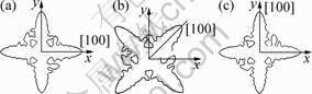
Fig. 2 Effect of random preferred orientation factor on dendrite preferential growth direction: (a) R[i, j]=0; (b) R[i, j]=0.707; (c) R[i, j]=1
Assuming that once embryos forms, the location of grains is fixed and the radius is larger than the critical nucleus radius, all the initial grains can grow successfully. The position of initial nucleation randomly distributes in the simulation domain. In addition, a plane which is constituted by all grain��s axes is parallel to the plane of two-dimensional simulation, which is shown in Fig. 2. The [100] direction of each grain is controlled by its random preferred orientation factor R[i, j].
2.3 Numerical issues
After considering the random distribution of dendrite preferred growth direction, the numerical calculation of anisotropic parameter shown as follows: the variable �� is instead of the random preferred orientation factor R[i, j] of any grid region in order to express conveniently.


 (8)
(8)
where the subscripts x and y mean the partial derivatives by x-axis and y-axis, respectively:
 ��
�� (9)
(9)
The calculations of other variable are the same as those of single grain in Ref. [6]. So the calculation in detail will not go into there.
The simulation domain is 500��x��400��y. The staggered grid is used, whose calculation precision is high. The space step is ��x=��y for simple calculation. The pressure and the phase-field control unit lie in the grid center, Ux and Uy at the boundaries of east and north of grid, respectively. The flow equations are solved numerically using sola algorithm method which is erected by self-adaptive pressure iteration method. Pressure does not need boundary condition. Based on the simulation experience of forced flow effect on single grain, the double dimensionless time steps are used. The phase field calculation time step ��t and the flow field calculation time step ��tf are 0.06 and 0.01, respectively.
Figure 3 shows the initial condition and boundary condition. Assume that there are four grains with the diameters of 2r, and distribute randomly in simulation domain. Incompressible non-Newtonian melt flows into at the left boundary and flows out at the right boundary, and the flowing into velocity is Ux. The initial pressure is 0, and all the conditions are shown as follows:
 (10)
(10)
Assume that the slip condition is at upside and underside boundary, and the no-slip condition is at a sharp solid-liquid interface of each grain. The Zero-Newman condition is used in phase-field and temperature field boundary.
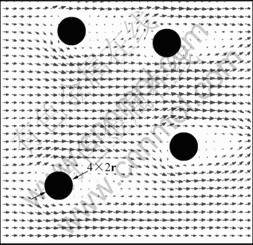
Fig. 3 Schematic diagram of initial condition
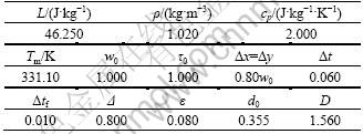
SCN has properties of metal and bcc structure with growth type of non-small-plane, Jackson factor of 0.97 and melting point of 58.1 ��C. The optical transparency, and complete data on physical and chemical properties were from Ref. [15]. Consequently, SCN was simulated in this work. The material parameters and computational parameters are listed in Table 1.
Table 1 Material parameters of pure SCN and computational parameters
3 Results and discussion
C language was used to make program with VC++ 6.0 as development platform, MATLAB and Tecplot as results visualization and data analysis softwares, respectively. The simulation run on PC: Intel(R) Core(TM) 2CPU 6600 @2.4GHz, 2.39 GHz, 1.00GB.
3.1 Relationship between force laminar flow and growth morphology of multiple grains
Figures 4(a), (b) and (c) show phase fields of undercooled melt without flow at solidification time of t=900��t, 1 800��t and 4 500��t, respectively. Figures 4(d), (e) and (f) show the phase-velocity fields when dimensionless flow velocity Ux is 0.06 at the same solidification time as Figs. 4(a), (b) and (c), respectively. The direction and length of arrowheads in the figures represent the melt particles flow direction and flow velocity, respectively. The contour legend in Fig. 4(f) is suitable for Figs. 4(a), (b), (c), (d) and (e), too. It can be found from Fig. 4 that the preferred growth directions of dendrite distribute randomly after using random preferred orientation factor R[i, j] with random grid method. The simulation result is mostly consistent with the objective fact. The computation time for getting Fig. 4(c) is 208 s, or 3.467 min. The computational efficiency is higher compared with Ref. [14].
Figures 4(a) and 4(d) show that each dendrite grows independently no matter the melt with flow or without flow. This is because the distance between each two grains is relatively far in early growth period.
Figures 4(b) and 4(e) show that the adjacent dendrite arms meet for dendrite with solidification going on. The melt flow direction becomes complex and the velocity value fluctuates violently. It is found from Fig. 4(e) that the direction and length of arrowhead change greatly for the effect of dendrite morphology, which represents that melt flow direction and velocity value change greatly.
In Fig. 4(e), several melt flow gaps caused by flowing through cross-section width become small at regions A and B. Effect of grain C on inflow cross-section width is little, so it is ignored. So, inflow capacity (cross-section width��flow velocity) is constant. With the growth of dendrite, the cross-section width becomes narrow and the flow velocity becomes high at the gap. As a result, the length and width of arrowhead become long and wide at the gap.
Comparing Fig. 4(b) with Fig. 4(e), we can find that the secondary or higher dendritic arms in upstream for melt with flow are more developed than those without flow. However, the dendritic arm in downstream side is dim and the secondary dendritic arm does not appear distinctly. What��s more, the dendrite perpendicular to flow has a tendency that grows toward to upstream. Because the latent heat is easier to spread in upstream of dendrite where is scoured by melt, the temperature gradient increases and the temperature boundary layer thickness become thin. On the contrary, the latent heat is hard to spread in downstream side so the temperature boundary layer is thick there. The changes of temperature boundary layer can be found in Figs. 5(a) and 5(b). Because undercooling is the driving force of solidification, the higher the temperature gradient, the more conducive the heat to the dendrite growth. In addition, tubercles of higher dendrites which are induced by thermal disturbance on the solid-fluid phase boundary will extend into undercooled melt and do not melt easily by latent heat. The tubercles will be successfully evolved into secondary or higher dendrite. Figure 6 shows the velocity field of forced flow effect upon 13 dendrites, in which the preferred growth direction randomly distributes in simulation. The study was made by AL-RAWAHI and TRYGGVASON [16]. It is found that the preferred growth direction distributes randomly and the upstream dendrite is more developed, the flow field is more complex by the effect of dendrite morphology. The entire conclusions agree well with our simulation results and conclusions.

Fig. 4 Dendritic patterns of melt at flow velocity of 0 (a, b, c) and phase velocity field at dimensionless flow velocity of 0.06 (d, e, f) at different time: (a), (d) t=900��t; (b), (e) t=1 800��t; (c), (f) t=4 500��t
When t=4 500��t, the phase field for melt without flow and phase-velocity field for melt with flow are shown in Figs. 4(c) and 4(f), respectively. The dendrite morphology has been very developed, the dendritic arms grow competitively and interlace. All of them have a ��one-sided�� tendency toward upstream. For melt with flow in Fig. 4(f), there are arrowheads in liquid region near left boundary and underside boundary where the dendritic arms are sparse. That is to say, the residual melt can flow only in this liquid region. However, the residual melt cannot flow in other region without arrowhead.

Fig. 5 Temperature-velocity field when dimensionless flow velocity is 0 (a) and 0.06 (b) at t=1 800��t

Fig. 6 Velocity field of forced flow effect on 13 dendrites [16]
Because the solid fraction is higher, the dendritic arms connect each other and almost occupy whole area of simulation. As a result, the melt flow channel is blocked or the residual melt is wrapped by dendritic arm in 2D simulation domain. The forced laminar flow imposing on the left boundary of simulation cannot affect the residual melt.
3.2 Relationship between forced laminar flow velocity and solid fraction of multiple grains
Figure 7 shows the relationship between the solidification time and the solid fraction when the dimensionless flow velocities are 0, 0.02 and 0.04. It can been seen that whether melt with flow or without flow, the solid fraction curve increases linearly when the solidification time is earlier than time point A (89��50��t); when the solidification time is later than point A, half of the simulation domain is occupied by dendritic arm, and the increment rates of solid fraction curves slow down for the effect of dendrite interaction between the dendrite and simulation boundary.
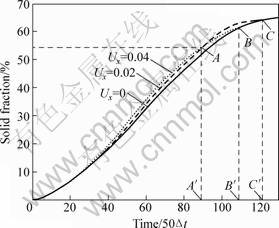
Fig. 7 Relationship between solid fraction and solidification time at different melt inflow velocities
It is found from Fig. 7 that the solid fraction increases with melt inflow velocity becoming high. This is because heat will spread not only by diffusion, but also by thermal convection. In addition, the higher the melt inflow velocity, the more intense the thermal convection. The change is not distinct at the initial stage of solidification for the effect of initial condition. Accordingly, latent heat spreads into bulk undercooled melt earlier and does not accumulate easy at solid-liquid interface. So, the solid fraction will increase with increasing inflow velocity.
The higher the melt inflow velocity, the easier the solid fraction equivalent to solid fraction for melt without flow. In Fig. 7, point B is intersect point of solid fraction curve of Ux=0.04 and Ux=0 at time B(109��50��t). Solid fraction is the same when the two curves coincide after time B��. Solid fraction curves of Ux=0.02 and Ux=0.00 intersect at point C when the solidification time is C(122��50��t). Point B�� is earlier than point C�� by about 650��t. Because the higher the inflow velocity is, the higher the dendrite growth rate is, and the smaller the region where residual melt can flow at the same time. So, solid fraction for melt with flow will gradually tend to be equal to solid fraction for melt without flow. What��s more, the higher the melt inflow velocity is, the earlier the solid fraction tends to be equal to solid fraction of melt without flow.
4 Conclusions
1) The problem of dendrite preferred growth direction was solved by random grid method designed by author. The simulation results are reasonable and the computational efficiency is higher.
2) Dendrite morphology, melt flow interact, and dendritic arm have ��one-sided�� tendency toward upstream. Melt flow velocity direction and value change greatly.
3) Solid fraction is in direct proportion to melt inflow velocity when the solid fraction is lower.
4) Little residual melt can flow when the solid fraction is higher. In addition, the higher the inflow velocity is, the earlier the solid fraction tends to be equal to solid fraction of melt without flow.
References
[1] NARSKI J, PICASSO M. Adaptive 3D finite elements with high aspect ratio for dendritic growth of a binary alloy including fluid flow induced by shrinkage [J]. Fluid Dynamics and Materials Processing, 2007, 3(1): 49-64.
[2] TONG X, BECKERMANN C, KARMA A, Li Q. Phase-filed simulations of dendritic crystal growth in forced flow [J]. Physical Review E, 2001, 63(6): 1-16.
[3] TONG X, BECKERMANN C, KARMA A. Velocity and shape selection of dendritic crystals in a forced flow [J]. Physical Review E, 2000, 61(1): 49-53.
[4] ZHU Chang-sheng, XIAO Rong-zhen, WANG Zhi-ping, FENG Li. Numerical simulation of recalescence of 3-dimensional isothermal solidification for binary alloy using phase-field approach [J]. Transactions of Nonferrous Metals Society of China, 2009, 19(6): 1286-1293.
[5] CHEN Zhi, CHEN Chang-le, HAO Li-mei. Numerical simulation of facet dendrite growth [J]. The Chinese Journal of Nonferrous Metals, 2008, 18(3): 938-943. (in Chinese)
[6] KARMA A, RAPPEL W J. Quantitative phase-field modeling of dendritic growth in two and three dimensions [J]. Physical Review E, 1998, 57(4): 4323-4349.
[7] BOETTINGER W J, WARREN J A, BECKERMANN C, KARMA A. Phase-field simulation of solidification [J]. Annual Review of Material Research, 2001, 32: 163-194.
[8] SUN Y, BECKERMANN C. Effect of solid-liquid density change on dendrite tip velocity and shape selection[J]. Journal of Crystal Growth, 2009, 311(4): 4447-4453.
[9] LONG Wen-yuan, L? Dong-lan, XIA Chun, PAN Mei-man, CAI Qi-zhou, CHEN Li-liang. Phase-field simulation of non-isothermal solidification dendrite growth of binary alloy under the force flow [J]. Acta Physica Sinica, 2009, 58(11): 7802-7808. (in Chinese)
[10] YUAN Xun-feng, DING Yu-tian, GUO Ting-biao, HU Yong, TANG Xiang-qian. Phase-field method of dendritic growth under convection [J]. The Chinese Journal of Nonferrous Metals, 2010, 20(4): 681-687. (in Chinese)
[11] CHEN Yun, KANG Xiu-hong, LI Dian-zhong. Phase-field modeling of free dendritic growth with a daptive finite element method [J]. Acta Physica Sinica, 2009, 58(1): 390-398. (in Chinese)
[12] ZHU Chang-sheng, WANG Zhi-ping, FENG Li, XIAO Rong-zhen. Phase-field simulation of multiple grain dendritic growth of binary alloy [J]. Journal of System Simulation, 2008, 20(23): 6514-6518. (in Chinese)
[13] YU Jing, XU Qing-yan, CUI Kai, LIU Bai-cheng. Numerical simulation of microstructure evolution based on a modified CA method [J]. Acta Metallurgica Sinica, 2007, 43(7): 731-738. (in Chinese)
[14] FENG Li, WANG Zhi-ping, LU Yang, ZHU Chang-sheng. Phase-field model of isothermal solidification of binary alloy with multiple grains [J]. Acta Physica Sinica, 2008, 57(2): 1084-1090. (in Chinese)
[15] DUAN Meng-meng, CHENG Chang-le, LI Zhan-yao, JIN Quan-wei. The effect of buoyancy driven convection on interface topography during solidification process [J]. Science in China, Series G, 2007, 37(3): 396-402. (in Chinese)
[16] AL-RAWAHI N, TRYGGVASON G. Numerical simulation of dendritic solidification with convection: two-dimensional geometry [J]. Journal of Computational Physics, 2002, 180(4): 471-496.
�������������ȡ��ྦྷ���������ೡ��ģ��
����ΰ1�����ʢ1, 2������ƽ1, 3���� ��1��Ф����1
1. ����������ѧ ����ʡ��ɫ�����²���ʡ�����������ص�ʵ���ң����� 730050��
2. ����������ѧ CAD���ģ����� 730050��
3. ����ʡ��ɫ���������ϲ��Ϲ����о����ģ����� 730050
ժ Ҫ��Ϊ�˸��۵�����ǿ�Ȳ����Զྦྷ�����̹��̵�Ӱ�죬���������������ӷ��Խ�����֦������������������ֲ����⡣�Ըߴ�������(SCN)Ϊ����������������ĵ��ೡģ���о�ǿ�Ȳ����Զྦྷ���ǵ����������̵�Ӱ�졣���������������ӷ����Ը������ش���֦������ȡ������ֲ����⣬����Ч�ʽϸߡ��������ʽϵ�ʱ�������ʵ��ƹ�֦���������β࣬��֦����֮������������ٶ�ֵ��������̼���ʱ��С��1800��tʱ������֦���������������β�֦���۾������β�֦���۷�����ң����������ٶ�Խ�죬������Խ�ߡ��������ʽϸ�ʱ�����֦�������֯������δ��֦�������IJ����������������ͬʱ������������������������ʱ�Ĺ�������ͬ��
�ؼ��ʣ��ೡ�����ྦྷ�������������������������ģ�⣻���̣������ٶ�
(Edited by YANG Hua)
Foundation item: Project (10964004) supported by the National Natural Science Foundation of China; Project (20070731001) supported by Research Fund for the Doctoral Program of China; Project (096RJZA104) supported by the Natural Science Foundation of Gansu Province, China; Project (SB14200801) supported by the Doctoral Fund of Lanzhou University of Technology, China
Corresponding author: WANG Jun-wei; Tel: +86-13619331460; E-mail: wtj3318@163.com; wangjw3318@mail2.lut.cn
DOI: 10.1016/S1003-6326(11)60905-9

