J. Cent. South Univ. Technol. (2007)04-0580-04
DOI: 10.1007/s11771-007-0111-3
Quality evaluation of layerlike backfilling and flow pattern of backfill slurry in stope
PENG Xin(彭 欣), LI Xi-bing(李夕兵), ZHANG Qin-li(张钦礼), WANG Xin-min(王新民)
(School of Resources and Safety Engineering, Central South University, Changsha 410083, China)
______________________________________________________________________________
Abstract:Stability condition and quality evaluation formula of layerlike backfilling roof, Q≥C, where Q denotes is quality index depending on allowable compressive or tensile strength and integrity of backfilling, and C is the technical index depending on mining method and backfilling technology, were inferred according to simply supported beam theorem. Technical treatment measures for instable backfilling roof, including optimum of appropriate filling materials and dosage for excellent flow property and reduction of backfill cost. It is proved that slope equation of backfill slurry in a stope to be filled is y=hexp[-x2/(2σ)2)], where h is height of cone and σ2 is mean square, and that optimum drainage point of backfill slurry can be determined by the equation and sizes of stope. Case study indicates that the results can give a theoretical support for quality evaluation and control of layerlike backfilling.
Key words: layerlike backfilling; quality evaluation; flow pattern; simply supported beam
______________________________________________________________________________
1 Introduction
Mineral resources are important material foundation of both national economy and humankind life. It is required to recover mineral resources as soon as possible on the condition of exploitation safety by its scarcity and non-renewable feature. Backfilling has become one of mining methods with great prospects owing to high recovery rate and reliable safety[1-4]. Cut and fill stoping is especially helpful for usage of large trackless vehicles and then has been widely employed in underground mines. Reliability of layerlike backfilling varies with filling technology and quality, and hidden dangers would exist while orebody of next sublevel is mined if layerlike backfilling is poor in quality. It is necessary, therefore, to develop quality evaluation approaches of layerlike backfilling, in order to keep backfill effects and increase safety and economic benefit of exploitation of mineral resources by adoption of appropriate management measures for backfilling with different qualities.
2 Stability condition of layerlike backfilling roof
Structure of layerlike backfilling is shown in Fig.1, where B and t denote the exposition span of backfilling and the height of first layer backfilling, respectively. Backfilling roof subsides downwards to rectangle space left by exploiting activities after orebody or rock below backfilling was excavated. Distribution of secondary stress within layerlike backfilling can be analyzed by simply supported beam theorem. Gravity load (P) exerted on beam is simply represented by unit weight of backfilling (γ/(t・m-3)) times the height of first layer backfilling (t/m), i.e. P=γt, as shown in Fig.2, in view of the fact that different layers are formed independently.
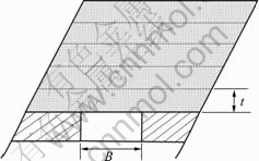
Fig.1 Layered structure of layerlike backfilling
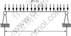
Fig.2 Load analysis of simply supported beam
The maximum tensile strength of rectangle layerlike backfilling roof (δt) is computed as follows according to simply supported beam theorem:
 (1)
(1)
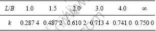
where k is a computation constant related to length(L) versus width(B) of the beam and can be selected from Table 1.
Table 1 Computation constant k of rectangle simply supported beam
Substituting P=γt into Eqn.(1) and converting unit of tensile strength into MPa, Eqn.(1) becomes:
 (2)
(2)
Eqn.(2) implies that the maximum tensile strength in the center of layerlike backfilling roof decreases with increasing the height of the first layer backfilling.
Stability condition of backfilling roof is given as follows if allowable tensile strength of backfilling is represented by |δt|:
 (3)
(3)
The following is a case study of some mine[5-6], where cut-and-fill mining was adopted, average length (L) and width (B) of a stope are 60 m and 12 m, and unit weight (γ) and allowable tensile strength (|δt|) of cemented backfilling are 1.98 t/m3 and 0.28 MPa, respectively. Height of the first layer backfilling corresponding to stable roof should be satisfied
 (m)
(m)
where k is 0.75 when L/B=5.
It is practically difficult that individual backfilling height reaches more than 7 m in cut-and-fill mining. In this case, the first layer backfilling quality should be raised or roof support should be supplied for safe exploitation of orebody below backfilling roof.
3 Quality evaluation approach of backfilling
It has been proven by the above analysis that backfilling quality depends on two factors: strength and integrity of the backfilling. The former includes allowable compressive strength (|δy|) and tensile strength (|δt|) of backfilling sample, and the latter can be expressed by height (t) of the first layer backfilling (direct roof of next level stope). Relationships between allowable compressive strengths and tensile strengths of some samples are illustrated in Fig.3.
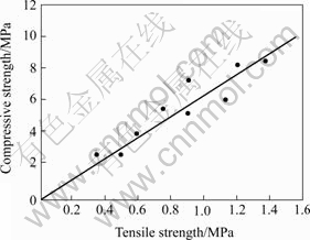
Fig.3 Relationship between compressive strength and tensile strength
Plots on |δy|-|δt| diagram are arranged almost as a straight line. |δy|-|δt| relation can be written as follows if the slope of the straight line is approximated as K.
|δy|=K|δt| (4)
or
 (5)
(5)
Substituting Eqn.(5) into Eqn.(3), the following equation can be obtained:
|δy|t≥kB2γK (6)
Let C=kB2γK and Q=|δy|t, then
Q≥C (7)
where Q denotes the quality index depending on allowable compressive or tensile strength and integrity of backfilling, and C the technical index depending on mining method and backfilling technology.
Eqn.(7) is quality evaluation criterion, indicating that backfilling roof is stable if Q≥C, and that backfilling roof may collapse if Q<C. There are two kinds of cases that backfilling does not meet the quality evaluation criterion: 1) allowable compressive strength |δy| is too low and then backfilling roof collapses easily in fragment, and 2) the first layer backfilling is too thin and then backfilling roof collapses easily in slice.
The following suggestions can be derived from quality evaluation of backfilling: 1) backfilling must have excellent flow property on condition of high strength through appropriate filling materials and dosage, so that integrity is secure, and 2) strength can be reduced appropriately if backfilling has good integrity, which is helpful for cost reduction and quality increase.
4 Flow pattern of slurry in stope
Backfilling slurry should have excellent flow property in order to reduce cost and increase quality as mentioned above. It is important, therefore, to study flow pattern of slurry in stope. Flow pattern of cemented rock backfill is discussed by some researchers[7], but that of backfill slurry with fine particles in a stope to be filled is seldom studied.
4.1 Flow pattern of slurry in an infinite horizontal plane
A backfilling cone with a circle pit on top is piled up in an infinite horizontal plane by slurry drained from backfill pipe as shown in Fig.4.
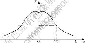
Fig.4 Flow section of slurry in infinite horizontal plane
Assuming that a particle moves along radial route OL from starting point O and OL is classified into m grades each having distance of Δx=OL/m, probability (p) of an event A that a particle settles down in any space Δxi(i=1, 2, 3, …, m) is p(A)=1, when particle settles down in Δxi, or p(A)=0, when particle does not settle down in Δxi.
Assuming that event A satisfies normal distribution of (0,σ2) based on Lyapunov’s central limit theorem, slope equation of backfill slurry is
 (8)
(8)
where h is height of cone and σ2 is mean square. Mean square reflects the slope of backfilling cone and is an important index because it is related to drainage point and times of backfilling slurry. The value of mean square varies with cement consumption, mass fraction of slurry and weighted average size of aggregate, and can be estimated by histogram of density function.
4.2 Flow pattern of slurry in stope
Flow pattern of slurry in a route stope where width of stope is rather less than its length is firstly studied for the sake of simplified theoretical analysis process. Assuming that filling pipe is installed in the center of route and distance from drainage point to end of route is x0. Slurry flows in the horizontal plane as normal distribution as discussed in section 4.1, but it cannot flow infinitely owing to such limit as surface tension of slurry and backfill quantity. It is common that slurry forms a circle with diameter of R. R is a constant when dosage of filling materials and filling technique are determined. Marginal height of slurry is defined as stable thickness d0.
It is known that
 (9)
(9)
when x=R. d0=1.25 m when R=25 m and h=4.0 m according to experience in Jinchuan Non-ferrous Metal Corporation (JNMC)[8].
Volume of cone is
 (10)
(10)
Solving Eqn.(10), the following equation can be obtained:
V=2πσ2h (11)
Slurry of 0.5B≤x≤R will pile upon slurry cone if backfilling space is limited. As a result, height of cone in width direction and diameter (R) of cone in length direction will be increased.
Volume of emptied space within range between drainage point and end of rote is
 (12)
(12)
The condition that stope is completely filled up (V′→0) is
x0=πσ2/B (13)
Drainage point is moved to another place by distance of x1 after the first time backfill activity is finished, and
x1=2πσ2/B (14)
in order to fill up whole space.
By combining Eqns.(13) and (14), optimum filling times is
 (15)
(15)
It should be noted that stope cannot be completely filled up practically because limit of backfilling slope[9]. It should be reasonable, therefore, to give an allowable untouched height h′max to top of route.
Normal distribution of backfilling pile indicates that backfilling volume is quantitatively related to its height and an emptied area as follows exists after backfilling in drainage point reaches top of route:

where H is the height of the route stope.
Average height of emptied area is

Let
A=πσ2/B
The above equation is simplified as
 (16)
(16)
It can be proven that following relationship exists between h′max and h′
h′max=βσh′ (17)
where β is a constant determined by field test.
Substituting Eqn.(17) into Eqn.(16), distance from the first time drainage point to end of route is gotten as follows:
 (18)
(18)
It is easily seen from Eqn.(18) that determination of reasonable drainage point is affected greatly by many factors, such as size of stope and surface shape of slurry pile. Distance from drainage point of next time to that of previous time is easily calculated as follows in the same way:
 n≥1 (19)
It may be necessary that drainage point is changed along width direction if width of ordinary cut-and-fill mining stope is large. Movement distance of drainage point can be determined according to the same approach discussed above.
4.3 Case study
Common size of route stope in JNMC is L×B×H=50 m×4 m×5 m[10-11], and constant β and mean square σ2 of backfill slurry with cement-crushed sand mass ratio of 1:4 are 9.5×10⁻⁴ and 10.24, respectively. Mining method and backfill technology give allowable untouched height of backfilling to roof of stope is 0.2 m. Eqns.(18) and (19) give movement distances of drainage point as follows: x0≤7.4 m; xn≤14.9 m, n≥1.
It has been proven by backfill experience in JNMC that layerlike backfilling is of good integrity and is stable when lower-level orebody is mined,as long as drainage point moves according to the above distances on condition that other filling factors satisfy the requirement of mining and backfilling technology.
5 Conclusions
1) Stability condition of backfilling roof is given as follows by simply supported beam theorem:
 ≤|δt|
≤|δt|
where B, γ, |δt|, t are width of stope, unit weight and allowable tensile strength of backfilling and height of first layer backfill, and k is a constant, respectively.
2) Backfilling quality should be raised or roof support should be supplied if height of the first layer backfilling cannot reach the value calculated by stability condition.
3) Another judging criterion whether backfilling roof is stable is Q≥C, where Q and C denote the quality index of backfilling and the technical index of backfilling technology, respectively.
4) Drainage point of backfill slurry can be determined by flow pattern of slurry in stope.
References
[1] ZHANG Qin-li, WANG Xin-min. Choice of filling materials and techniques in Xinqiao Pyrite Mine[J]. Trans Nonferrous Met Soc China, 1997, 7(4): 169-171.
[2] ZHANG Qin-li, WANG Xin-min, GU De-sheng, et al. A study of fly ash backfill technology in Xinqiao Pyrite Mine[C]// Proceedings of the 8th International Symposium on Mining with Backfill. Changsha: The Nonferrous Metal Society of China, 2004: 99-103.
[3] ZHOU Ai-min. Mining backfill technology in China [C]// Proceedings of the 8th International Symposium on Mining with Backfill. Changsha: The Nonferrous Metal Society of China, 2004: 1-11.
[4] ZHANG Qin-li, WANG Xin-min. Performance of cemented coal gangue backfill[J]. Journal of Central South University of Technology, 2007, 14(2): 216-219.
[5] WANG Xin-min, ZHANG Qin-li, CHEN Jia-sheng. Tests and practice of a new technique of cemented rockfill in Xinqiao Pyrite Mine[J]. The Chinese Journal of Nonferrous Metal, 1997, 7(3): 10-13. (in Chinese)
[6] WANG Xin-min, ZHANG Qin-li, PENG Xu-cheng, et al. The mining technology of large span length stope[J]. Journal of Central South University Technology: Natural Science, 1998, 29(1): 14-17. (in Chinese)
[7] FARSANGI P, HARA A. Consolidated rockfill design and quality control at Kidd Creek Mines[J]. CIM Bulletin, 1993, 6(972): 68-74.
[8] WANG Xin-min, XIAO Wei-guo, ZHANG Qin-li. Backfill Technology in Deep Filling[M]. Changsha: Central South University Press, 2004. (in Chinese)
[9] CHEN D, MESSURIER M L, MITCHELL B. Application of cemented aggregate fill at Barrick’s Darlot Gold Mine[C]// Proceedings of the 8th International Symposium on Mining with Backfill. Changsha: The Nonferrous Metal Society of China, 2004: 82-89.
[10] LIU Tong-you. Filling Technology and its Application[M]. Beijing: Metallurgical Industry Press, 2001. (in Chinese)
[11] YU Xue-fu, LIU Tong-you. Filling mechanism and mining theory in Jinchuan Mine[R]. Jinchuan: 4th National Rock Mechanism Symposium, 2001. (in Chinese)
_________________________
Foundation item: Project(50490270) supported by the National Natural Science Foundation of China
Received date: 2007-01-12; Accepted date: 2007-03-27
Corresponding author: PENG Xin, Doctoral candidate; Tel: +86-751-6618780; E-mail: pxhn@tom.com
(Edited by YANG Hua)

