J. Cent. South Univ. Technol. (2007)04-0546-06
DOI: 10.1007/s11771-007-0105-1
Relationship between subsurface damage and surface roughness of ground optical materials
LI Sheng-yi(��ʥ��), WANG Zhuo(�� ), WU Yu-lie(������)
(College of Mechatronic Engineering and Automation, National University of Defense Technology,Changsha 410073, China)
______________________________________________________________________________________
Abstract: A theoretical model of relationship between subsurface damage and surface roughness was established to realize rapid and non-destructive measurement of subsurface damage of ground optical materials. Postulated condition of the model was that subsurface damage depth and peak-to-valley surface roughness are equal to depth of radial and lateral cracks in brittle surface induced by small-radius (radius��200 ��m) spherical indenter, respectively. And contribution of elastic stress field to the radial cracks propagation was also considered in the loading cycle. Subsurface damage depth of ground BK7 glasses was measured by magnetorheological finishing spot technique to validate theoretical ratio of subsurface damage to surface roughness. The results show that the ratio is directly proportional to load of abrasive grains and hardness of optical materials, while inversely proportional to granularity of abrasive grains and fracture toughness of optical materials. Moreover, the influence of the load and fracture toughness on the ratio is more significant than the granularity and hardness, respectively. The measured ratios of 80 grit and 120 grit fixed abrasive grinding of BK7 glasses are 5.8 and 5.4, respectively.
Key words: subsurface damage; spherical indenter; optical materials; grinding process; magnetorheological finishing
______________________________________________________________________________________
1 Introduction
Subsurface damage (SSD) influences operational life, secular stability, imaging quality, coating quality, and laser-induced damage threshold of optical elements[1-3]. Subsurface cracks can affect laser damage susceptibility in field intensification due to interference, enhanced absorption due to trapped material in the cracks, and increased mechanical weakness, and then induce macroscopic damage to optics[4-5].
It is unresolved in detecting and assessing SSD for it is covered under surface. If there exists relationship between SSD and surface roughness (SR), SSD can be rapidly and accurately predicted through SR, for SR measurement is convenient. There are lots of experiment results[6-8] and several preliminary theories[9-10] towards the relationship between SSD and SR of optical materials. Assuming that SSD depth and peak-to-valley (p-v) SR were equal to depth of radial cracks and lateral cracks, respectively, LAMBROPOULOS established a model for ratio of SSD to SR in deterministic microgrinding process via investigating cracks system on brittle surface induced by sharp indenter (Vickers indenter)[9]. Assuming that SSD depth and p-v SR were equal to depth of Hertzian cracks and static lateral cracks, respectively, MILLER established a model for ratio of SSD to SR via investigating cracks system in brittle surface induced by blunt indenter (spherical indenter)[10]. But, it is difficult to accurately obtain shape of abrasive grains by LAMBROPOULOS model. And the size of abrasive grains in optical manufacture is generally smaller than that in MILLER model, so no Hertzian cracks will be produced. Moreover, the two models neglect the effect of abrasive grains size on the ratio of SSD to SR. In fact, geometrical properties (shape and size) of abrasive grains are very important for SSD generation in optical manufacture. Therefore, the two models are not suitable for predicting the ratio of SSD to SR in optical grinding process.
In this paper, a model for ratio of SSD to SR suitable for optical grinding process was established, via investigating radial and lateral cracks system in brittle surface induced by small-radius (radius��200 ��m) spherical indenter. With this model, the depth of SSD generated by grinding process can be predicted accurately through measuring SR of ground optical elements. Therefore, the rapid and non-destructive measurement of SSD can be realized. Eventually, quality and efficiency of optical machining can be improved effectively.
2 Physical basis of SSD/SR model
The physical basis for the correlation between SSD depth and SR may be the result of the characteristics of the fractures that lead to SSD and surface morphology, respectively[10].
2.1 Depth of radial cracks
Indentation of spherical indenter typically generates Hertzian cracks, which nucleate first as ring cracks on the material surface and then propagate into complete Hertzian cracks under further loading. There is no plastic deformation during entire indentation[11]. However, indentation of small-radius (radius��200 ��m) spherical indenter will induce irreversible deformation beneath contact site, when contact load exceeds a critical value (less than nucleation load of Hertzian cracks). Further increase of contact load leads to well-developed plasticity and formation of radial and lateral cracks system characteristic of elastic-plastic contact[12]. If plastic deformation occurs during spherical contact of brittle surface, radial cracks form in the loading cycle (the radial cracks are called median cracks in Ref.[11]), and lateral cracks form just before complete unloading[11].
Driving force for radial cracks formation generated by small-radius spherical indenter is residual stress field due to mismatch of elastic/plastic deformation after unloading. MARSHALL proposed an expression for residual stress intensity factor of indentation stress field[12]:
 (1)
(1)
where �� is a dimensionless constant independent of material properties and indenter shape, E is elastic modulus, H is hardness, ��V is indentation volume, and rc is depth of radial cracks.
The volume of an indentation formed by a sphere of radius R is[12]
 (2)
(2)
where ra is radius of impression zone.
The hardness of spherical indentation is defined by
H=p/(��ra2) (3)
where p is indentation load.
Condition for equilibrium cracks growth is given by equating Kr to the fracture toughness, (Kc), of the material.
Kc=Kr �� (4)
Combining Eqns.(1)-(4) yields
 (5)
(5)
The depth of radial cracks, induced by residual stress field after complete unloading, can be calculated by Eqn.(5). But radial cracks form in the loading cycle and propagate into final size when the peak load is achieved. And for the irreversibility of crack propagation, radial cracks will not close in the unloading cycle. The indentation stress field beneath the contact impression is composed of elastic stress field, induced by indentation load, and residual stress field, induced by mismatch of elastic/plastic deformation of indentation, in the loading cycle[13]. So the contribution of the elastic stress field to the radial cracks propagation must be considered in calculating the depth of radial cracks. Then Eqn.(5) becomes
 (6)
(6)
where �� is correction factor of depth of radial cracks considering the elastic stress field.
The depth of radial cracks on brittle surface induced by small-radius spherical indenter can be predicted by Eqn.(6).
2.2 Depth of lateral cracks
Driving force and initiation mechanisms for lateral cracks depend on elastic and plastic material properties in a more subtle way than for radial cracks. Lateral cracks may form at any indentation time, even at complete unloading, and propagate driven by residual stress field[11]. Lateral cracks are observed to initiate near the base of the plastic deformation zone below the indentation, and to spread out laterally on a plane closely parallel to the specimen surface[14]. Observations (and numerical calculations) indicate that the plastic zone exhibits spherical symmetry, regardless of indenter geometry[12,15]. Therefore, it is reasonable that the depth of lateral cracks is equal to plastic zone size after the spherical indenter complete unloading.
Indentation mechanics can be simplified by considering the displaced material as occupying the volume of an equivalent half-sphere of radius rar.
 (7)
(7)
Length scales rar (radius of indented half-sphere) and rb (plastic zone size) can be correlated via the Hill model of the expanding cavity in a perfectly plastic material[9,15].
 �� (8)
where m is a dimensionless constant ranging from 1/3 to 1/2.
Combining Eqns.(7) and (8) obtains
 (9)
(9)
The depth of lateral cracks on brittle surface induced by small-radius spherical indenter can be predicted by Eqn.(9).
3 Model for ratio of SSD to SR
It is generally held that material is removed by the formation of lateral cracks beneath the contact impression, at approximately a depth of the plastic zone, followed by their subsequent outward propagation and final emergence to the material surface. This would lead to a craterlike morphology in which the contact impression is entirely removed[11].
Assuming that SSD depth and p-v SR are equal to depth of radial cracks and lateral cracks, respectively, cracks system on brittle surface induced by small-radius indenter at complete unloading are shown in Fig.1.
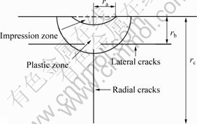
Fig.1 Cracks system on brittle surface induced by small-radius indenter at complete unloading
Combining Eqns.(6) and (9), model for the ratio(n) of SSD to SR on brittle surface induced by small-radius spherical indenter can be achieved:
 (10)
(10)
where
 (11)
(11)
From Eqn.(10), it is clear that the SSD/SR ratio is determined by material mechanical properties (elastic modulus, hardness, and fracture toughness), geometrical properties and load of abrasive grains. Optical material is typically hard brittle material and the shape of abrasive grains, which is quite irregular in grinding process, is simplified as a sphere, so Eqn.(10) can be applied to calculating the ratio of SSD to SR of ground optical materials. Utilizing the SSD/SR model, depth of SSD generated by grinding process can be predicted accurately through measuring SR of ground optical elements.
More data analysis suggests that m=1/3 may be more appropriate[9]. ANSTIS et al[16] calibrated the dimensionless constant �� by plotting data obtained from Vickers indentations in a wide range of ceramic materials, yielded ��=0.096. MARSHALL et al[17] verified that predicted results from spherical indentations with ��=0.096 show good agreement with measurements[12]. LAWN determined indentation coefficients of radial cracks through sharp indentation experiments. The indentation coefficients for elastic stress field and residual stress field beneath the contact impression were  =0.032 and
  =0.026, respectively[13]. Therefore, the correction factor of radial cracks depth considering the elastic stress field is ��=1+/=2.23. And taking the mechanical properties of BK7 glasses (E=81 GPa��H=7.2 GPa��and Kc =0.82 MPa
 ), load of abrasive grains (ranging from 0.1 to 10 N)[9], and granularity of abrasive grains (ranging from 100 to 400 ��m) into Eqn.(10), the relationship between the SSD/SR ratio and granularity and load of abrasive grains of ground BK7 glasses can be achieved, as shown in Fig.2.
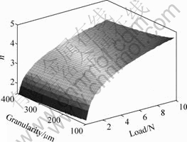
Fig.2 SSD/SR ratio (n) versus granularity and load of abrasive grains in BK7 glasses grinding
Fig.2 shows that the SSD/SR ratio is directly proportional to load of abrasive grains, while inversely proportional to granularity of abrasive grains, especially. The reason for this is that is at the same load the larger the abrasive grain size, the less the surface pressure and the less the SSD. Moreover, influence of the load on the SSD/SR ratio is more significant than on the granularity.
Choosing three typical optical materials FS-C7940 (E=73 GPa��H=8.5 GPa��Kc =0.75 MPa), BK7 glasses, and TaFD5(E=126 GPa��H=10 GPa��Kc= 1.54 MPa)[9], the relationship between the SSD/SR ratio and material mechanical properties is shown in Fig.3. The load of abrasive grains is 10 N.
Fig.3 and Eqn.(10) show that mechanical properties material of (hardness and fracture toughness) affect the SSD/SR ratio severely. And the SSD/SR ratio is directly proportional to hardness, while inversely proportional to fracture toughness. Moreover, influence of the fracture toughness on the SSD/SR ratio is more significant.
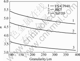
Fig.3 SSD/SR ratio (n) of three typical optical materials at 10 N load of abrasive grains
4 Experimental 4.1 Sample surface preparation
Several BK7 glasses (100 mm diameter��10 mm thickness) were ground by a parallel plane grinding machine MGK7120��6, using SD80N100B3.0(180-212 ��m granule size) and SD120N100B3.0(106-125 ��m granule size) diamond grit resin bonded wheel. Linear speed at the edge of the wheels was 30 m/s, cross feed rate was 42 mm/s, and depth of cut was 40 ��m. The surface roughness of the 80 grit and 120 grit ground BK7 glasses are 9.2 and 7.0 ��m, respectively, which was measured by Taylor Hobson Talysurf 6 surface contacting profilometer.
4.2 SSD depth measurement
MRF (magnetorheological finishing) spot technique is less destructive and more efficient in measuring SSD compared with dimpling method. Moreover, the large area of the MRF spot implies that it reveals the more SSD zone, and the shallower slopes imply a greater sensitivity to the detection of SSD[8]. Therefore, SSD depth was measured by MRF spot technique in our work. There were three spots on each ground surfaces polished by MRF process, as shown in Fig.4. The surfaces were etched with 1% HF for 30 s in order to open the cracks and enable SSD properly to be viewed. The MRF spots depth profile across the centerline were measured by a profilometer (vertical resolution is 0.01 ��m), as shown in Fig.5. The samples were placed on an inching platform (horizontal resolution is 1 ��m) after ultrasonic cleaning and viewed along the leading edge and the trailing edge of the MRF spots with an optical microscope at magnification of 400, as shown in Fig.6. Applying the horizontal distance of the last cracks obtained from the inching platform to the depth profile obtained from the profilometer yield the depth of SSD (the last cracks of spot 3 in sample 2, along the leading edge, vanish at the depth of 52.7 ��m, shown in Fig.6(f)). At each MRF spot, depth of SSD was the equalizing value of the two measurement results along the leading edge and the trailing edge. And by averaging SSD depth of 6 MRF spots (on 2 samples), SSD depth generated by certain grinding process conditions was achieved.
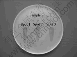
Fig. 4 80 grit ground sample and three MRF spots
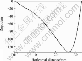
Fig. 5 Depth profile across centerline of spot 3 on sample 2
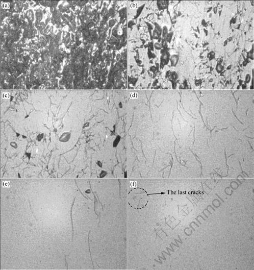
(a) 0.6 ��m under surface;(b) 3.0 ��m under surface; (c) 7.9 ��m under surface; (d) 16.0 ��m under surface;
(e) 34.8 ��m under surface; (f) 52.7 ��m under surface
Fig. 6 Subsurface cracks micrographs of spot 3 on sample 2
4.3 Results and discussion
SSD depth of 80 grit and 120 grit ground BK7 glasses is 52.9 and 38.0 ��m, respectively. According to the surface roughness and the SSD depth, the SSD/SR ratios of the two grinding process conditions are 5.8 and 5.4, respectively.
HED et al[7] investigated the relationship between subsurface damage depth and surface roughness for bound abrasive tools (diamond size 60-220 ��m). For BK7 and Zerodur, they found the ratio of SSD depth to peak-to-valley surface roughness as 6.4��1.3. It is obvious that measured SSD/SR ratios of the ground BK7 glasses are in this range. However, the theoretical ratio is less than 5, as shown in Fig.2. The reason is that shape of the abrasive grains is assumed spherical in the SSD/SR model. Actually, the abrasive grains shape is quite irregular (multi-pyramidal structure in macroscopic view), similar to sharp indenter, because the growth mechanics of abrasive grains crystals for abrasion wheel manufacture or breaking method of pelletization is different. So, there are greater measured SSD/SR ratios than the theoretical ones. Moreover, the dimensionless constant ��s in the SSD/SR model is achieved by measurement results of single indentation and correlated proportion coefficient, whereas interaction among indentations and reloading of indenters is very complex in optical grinding process, which will improve SSD/SR ratio further. Therefore, the dimensionless constant ��s in Eqn.(10) must be corrected by more practical measurement results.
5 Conclusions
1) A model for ratio of SSD to SR suitable for optical grinding process was established. With this model, SSD/SR ratio of ground optical materials can be effectively predicted by material mechanical properties (hardness and fracture toughness), geometrical properties and load of abrasive grains.
2) The SSD/SR ratio is directly proportional to load of abrasive grains, while inversely proportional to granularity of abrasive grains, especially. Moreover, the influence of the load on the SSD/SR ratio is more significant.
3) Mechanical properties of material affect SSD/SR ratio severely. And, the SSD/SR ratio is directly proportional to hardness, while inversely proportional to fracture toughness. Moreover, influence of the fracture toughness on the SSD/SR ratio is more significant.
References
[1] FINE K R, GARBE R, GIP T, et al. Non-destructive, real time direct measurement of subsurface damage[C]// Proceedings of SPIE. Bellingham, 2005: 105-110.
[2] CAMPBELL J H, HAWLEY-FEDDER R A, STOLZ C J, et al. NIF optical materials and fabrication technologies: An overview[C]// Proceedings of SPIE. Bellingham, 2004: 84-101.
[3] SHEN J, LIU S H, YI K, et al. Subsurface damage in optical substrates[J]. Optik, 2005, 116: 288-294.
[4] LIU Shu-jiang, LU An-xian, TANG Xiao-dong, et al. Spectral properties of Yb3+-doped silicate and phosphate laser glass[J]. Journal of Central South University: Science and Technology, 2006, 37(3): 433�C437. (in Chinese)
[5] HAMZA A V, SIEKHAUS W J, RUBENCHIK A M, et al. Engineered defects for investigation of laser-induced damage of fused silica at 355 nm[C]// Proceedings of SPIE. Bellingham, 2002: 96�C107.
[6] G?NIN F Y, SALLEO A, PISTOR T V, et al. Role of light intensification by cracks in optical breakdown on surfaces[J]. Journal of the Optical Society of America, 2001, 18(10): 2607�C2616.
[7] HED P P, EDWARDS D F. Optical glass fabrication technology. 2: Relationship between surface roughness and subsurface damage[J]. Applied Optics, 1987, 26(21): 4677�C4680.
[8] YANG F Q. Effect of subsurface damage on indentation behavior of ground ULETM glass[J]. Journal of Non-Crystalline Solids, 2005, 351(54): 3861�C3865.
[9] RANDI J A, LAMBROPOULOS J C, JACOBS S D. Subsurface damage in some single crystalline optical materials[J]. Applied Optics, 2005, 44(12): 2241-2249.
[10] LAMBROPOULOS J C. Material removal mechanisms from grinding to polishing[C]// Finishing of Advanced Ceramics and Glasses, Ceramic Transactions. Westerville, 1999: 113�C128.
[11] MILLER P E, SURATWALA T I, WONG L L, et al. The distribution of subsurface damage in fused silica[C]// Proceedings of SPIE. Bellingham, 2005: 1�C13.
[12] ZHOU Xiao-ping, LING Tong-hua. Elastoplastic analysis for infinite plate with centric crack loaded by two pairs of point shear forces[J]. Journal of Central South University of Technology, 2005, 12(Suppl. 1): 189�C193.
[13] COOK R F, PHARR G M. Direct observation and analysis of indentation cracking in glasses and ceramics[J]. Journal of the American Ceramic Society, 1990, 73(4): 787�C817.
[14] MARSHALL D B. Geometrical effects in elastic/plastic indentation[J]. Journal of the American Ceramic Society, 1983, 67(1): 57�C60.
[15] LAWN B R, EVANS A G, MARSHALL D B. Elastic/Plastic indentation damage in ceramics: The median/radial crack system[J]. Journal of the American Ceramic Society, 1982, 63(9/10): 574�C581.
[16] ANSTIS G R, CHANTIKUL P, LAWN B R, et al. A critical evaluation of indentation techniques for measuring fracture toughness: I[J]. Journal of the American Ceramic Society, 1981, 64(9): 533�C538.
[17] MARSHALL D B, LAWN B R, EVANS A G. Elastic/Plastic indentation damage in ceramics: The lateral crack system[J]. Journal of the American Ceramic Society, 1982, 65(11): 561�C566.
___________________________
Foundation item: Project(50375156) supported by the National Natural Science Foundation of China
Received date: 2006-10-24; Accepted date: 2006-12-27
Corresponding author: LI Sheng-yi, Professor; Tel: +86-731-4574938; E-mail: syli@nudt.edu.cn
(Edited by YANG Hua)

