
J. Cent. South Univ. (2020) 27: 1262-1272
DOI: https://doi.org/10.1007/s11771-020-4365-3

Numerical simulation of freezing effect and tool change of shield machine with a frozen cutterhead
DAI Wei(��Ϊ)1, 2, XIA Yi-min(������)1, XU Hai-liang(�캣��)1, YANG Mei(����)1
1. College of Mechanical and Electrical Engineering, Central South University, Changsha 410083, China;
2. China Railway 25th Bureau Group Co., Ltd., Guangzhou 510600, China
 Central South University Press and Springer-Verlag GmbH Germany, part of Springer Nature 2020
Abstract: A shield machine with freezing function is proposed in order to realize tool change operation at atmospheric pressure. Furthermore, the transformation project of freezing cutterhead and tool change maintenance method are put forward. Taking the shield construction of Huanxi Power Tunnel as an example, a numerical analysis of the freezing cutter head of the project was carried out. The results show that when the brine temperature is -25 ��C, after 30 d of freezing, the thickness of the frozen wall can reach 0.67 m and the average temperature drops to -9.9 ��C. When the brine temperature is -30 ��C, after 50 d of freezing, the thickness of the frozen wall can reach 1.01 m and the average temperature drops to -12.4 ��C. If the thickness of the frozen wall is 0.5 m and the average temperature is -10 ��C, as the design index of the frozen wall, the brine temperature should be lower than -28 ��C to meet the excavation requirements in 30 d. Analyzing the frozen wall stress under 0.5 m thickness and -10 ��C average temperature condition, the tensile safety factor and compressive safety factor are both greater than 2 at the most dangerous position, which can meet the tool change requirements for shield construction.
Key words: shield machine; construction; frozen cutterhead; tool change maintenance; finite element simulation
Cite this article as: DAI Wei, XIA Yi-min, XU Hai-liang, YANG Mei. Numerical simulation of freezing effect and tool change of shield machine with a frozen cutterhead [J]. Journal of Central South University, 2020, 27(4): 1262-1272. DOI: https://doi.org/10.1007/s11771-020-4365-3.
1 Introduction
The cutterheadbody and the cutterhead installed on the cutterhead face will be in direct contact with the excavation of soil during shield tunneling. In the process of mutual friction and collision, the cutterhead body is prone to crack, abnormal wear and other failures. In the process of installation, the cutterhead body is prone to eccentric wear, sealing failure, edge collapse and other failures. Among them, the cutter wear is the main failure phenomenon encountered in the construction process of shield machine. When the corresponding failure phenomenon occurs in the field construction process, it is necessary to maintain the failed tool and cutter head accordingly [1-3].
There are two main maintenance methods in the existing maintenance procedure. One is normal pressure warehouse entry maintenance, which needs staff to enter into the excavation warehouse on the back of the cutterhead. The other is pressurized warehouse entry maintenance, which needs staff to bear the soil and water pressure of construction stratum to enter into the back of the cutterhead [4-6]. Comparing the two maintenance methods, the working conditions under normal pressure is superior to those under pressure and requires lower technical requirements for constructors but higher construction stratum. The application in normal pressure work is wider than under pressure work but higher to requirements of constructor��s technical ability and physical quality. What��s more, higher construction risk and engineering accident may easily occur [7, 8]. Thus, a technology to realize the shield tool change in normal pressure is urgently needed to research, which can effectively reduce the working time and construction cost wasted by cutter wear and tool change operating risk of constructors.
As is known to all, the freezing effects of the cutterhead are based on the soil temperature, whose distribution law was decided by the soil thermophysical properties. According to the existing research, it can be concluded that the soil thermophysical properties mainly included the soil freezing temperature under construction geological conditions, unfrozen water content and ice content, thermal conductivity, specific heat and phase transformation latent heat [9-13]. To confirm that these parameters are very important to calculate the temperature field of frozen soil in front of cutterhead, ROMAN [14], SURIKOV [15], ANDERSLAND [16] and others elaborated on the thermophysical properties of frozen soil. The parameters of the thermophysical properties in engineering usually were took by the field tests. A lot of useful works on the soil thermophysical properties have done through experiment and theoretical analysis. The key point of the existing research is to extract the influencing factors of soil thermal conductivity based on the original research and combined with the actual engineering, and to obtain the temperature distribution law in the existing excavated soil by the means of experiment and numerical simulation, so as to build the mathematical model of soil thermophysical properties in line with the actual engineering.
At present, scholars at home and abroad mainly study the application of freezing method to strengthen the stratum on the basis of model test and actual measurement [17-20]. The advantage of model tests is that it can reproduce the freezing process in a short time and study the variable parameters under controllable conditions. However, these works are difficult to realize in practical engineering [21-23]. The freezing effects of the artificial ground always influenced by the operation state of the cooling system, geological conditions, boundary condition of scattering heat, construction conditions and so on. The structure state of the frozen soil was the function of temperature, while the temperature field of the frozen soil varied by time. To assume the safety and effectiveness of the frozen curtain, it was necessary to grasp the various parameters. What��s more, real-time monitor of the change of freezing temperature field, displacement field and stress field was obligatory too. So that the monitoring can feedback construction information, modify design deviation and ensure the construction safety.
From the freezing construction case study, the freezing method was widely used in the existing tunnel and underground engineering [24-26]. But the shield construction and freezing construction were seldom combined effectively in the previous case study. There was still difference between the soil freezing, whose frozen source was the shield machine, and the existing freezing construction. The thermal dissipation law between conventional freezing method and shield machine cutterhead freezing method differed too. Hence, the cutterhead freezing experiment was still necessary to be conducted by the existing conditions to analyze the feasibility of the freezing construction and its freezing effect.
For the above problems, a shield cutter head with freezing function is proposed in this paper. The soil temperature in the tunnel face of the cutterhead was reduced by a cooling circulation pipe embedded on the cutterhead. The soil in front of the cutterhead is frozen to create the corresponding atmospheric pressure construction environment for the tool change maintenance operation of the shield machine.
Through this technology, the construction risk and technical requirements in the process of cutter maintenance are reduced compared with the conventional method. Furthermore, the maintenance cost of cutter head and cutter is reduced within one month, compared with more than one month required by the traditional grouting reinforcement method [27, 28]. At present, there are few related technologies used in the existing shield machine maintenance technology, so the research of this work may be of great significance for shield machine maintenance.
2 Freezing transformation and tool change method of shield machine
Based on the structure characteristic and working theory of shield machine, the transformation design of cutterhead, tool change maintenance was put forward below.
1) Cutterhead transformation design
Add refrigerating unit, storage tank and heating device at the back auxiliary system of shield machine, and add freezing circulation pipeline inside or on the side of the cutterhead and inside or outside the shield body, so that the shield machine can freeze liquid, semi liquid and solid substances around the cutterhead, slurry bin and shield body in a certain area. A heating pipeline is installed on one side of the front partition near the air cushion chamber. The high-temperature heat-transfer fluid is respectively input into the heating pipeline and the freezing pipeline through the heating device to protect the main drive unit, the central rotary joint and the thawing and freezing area.
2) The freezing and maintenance process of shield machine with freezing function
The freezing pipeline added in the shield machine is used to freeze the designated area, so as to realize the freezing function. When freezing the slurry bin and shield body in a certain area, open the freezing pipeline valve at the cutterhead and shield body, inject the refrigerant into the freezing circulation pipeline, and at the same time, heat the pipeline at the front clapboard and input the heat transfer fluid to prevent the main driving single element affected by low temperature. After freezing for a certain period of time, determine the freezing effect of the frozen area through the reserved holes on the front clapboard. When the frozen area meets the relevant requirements, connect the frozen pipeline with the freezing unit to conduct heat preservation treatment for the frozen target area. Then, the staff from the back clapboard can go into the mud warehouse, clean the frozen area and maintain the cutters or cutterhead. After the maintenance work is completed, at the same time, the high-temperature heat-transfer fluid is input into the freezing pipeline, and the residual substances in the frozen area are brought out through the slurry discharge pipe.
3) Tool change method of shield machine
When the shield machine stops working, the slurry circulating system will keep working until most of the stone particles and impurities in the mud warehouse are discharged. When the mud warehouse is cleaned, the cutterhead will keep a certain rotation speed to facilitate the cleaning and transportation of the stone particles and other impurities in the mud warehouse. Until the residual impurity is clear up in the mud warehouse, the cutterhead stopped rotating. Then, the freezing system starts to work to freeze the mud, cutterhead and soil around the shield, release the compressed air in the air warehouse and open the warehouse under normal pressure. At this time, the refrigeration system continues to work to ensure the low temperature in the mud warehouse. Using digging tools to dig the frozen soil manually and then replace the worn cutter. Finally, the air warehouse is pressurized, then the slurry inlet pipe is thawed, and the mud is filled into the excavated area of the mud warehouse. After the air warehouse is pressurized and the mud is filled, the residual frozen body of the mud warehouse is thawed by injecting heat-transfer fluid into the circulating pipe.
3 Case study
Taking the Huanxi Power Tunnel shield construction as an example, the shield machine in this section was designed for refrigeration transformation. Based on the relevant design results and finite element simulation, the feasibility was analyzed, and the relevant parameters were determined to provide the theoretical basis and data support for the field test. Some of the site pictures are shown in the Figure 1.
3.1 Analysis of three-dimensional freezing temperature field
3.1.1 Finite element model
A three-dimensional model was established to solve the temperature field problem. Within the scope of the study, the soil and cutterhead were considered to be uniform and continuous. The initial temperature of the soil and cutterhead was equivalence constant (First boundary condition). When the soil was freezing, the latent heat concentrated in the frozen interface will release continuously. All above are based on an assumption that all the water in the soil was frozen and the unfrozen water were zero.

Figure 1 Experimental site of Huanxi Power Tunnel shield construction
When it comes to the symmetry, 1/4 of the shield machine model was established and the condenser pipe was set up on the spokes. The thickness of the soil in front of the shield machine and right-and-left was 10 m. The layout of the cutterhead and condenser pipe was shown in Figure 2 and the whole model was shown in Figure 3. Tetrahedral element was used for mesh generation, and the mesh generation diagram of finite element was shown in Figure 4.

Figure 2 Layout of shield machine cutterhead and condenser pipe (Unit: m)
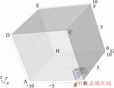
Figure 3 Whole finite element calculation model (Unit: m)
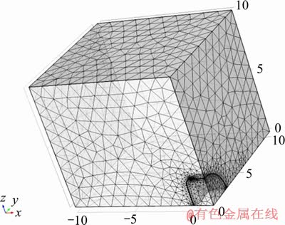
Figure 4 Mesh partition diagram of finite element model (Unit: m)
3.1.2 Boundary conditions and calculation parameters
The initial temperature of soil and condenser pipe was 18 ��C. Area of ADEH, EFGH, CDEF in the Figure 3 was thermostabilized boundary and temperature was primary earth temperature. When it comes to the symmetry, area of ABCD and ABGH was adiabatic boundary. Area of BCFG was disposed approximatively by adiabatic boundary, because the back of cutterhead of the shield machine was disposed to be insulated and the developing trend of the temperature field of the back of shield machine was not the focus area. The thermophysical parameters of soil and condenser pipe were shown in Table 1.
The temperature outside of the surface of condenser pipe was the important freezing effect factor. Three different projects were adopted to calculate the temperature outside of the surface of condenser pipe. After certain period of cooling (One week after freezing, the brine temperature drops below 0 ��C. Two weeks after freezing, the brine temperature decreases to below -20 ��C), the brine temperatures were stable at -25 ��C, -28 ��C and -30 ��C, respectively.
Table 1 Thermophysical parameters of soil and condenser pipe

3.1.3 Calculation results and analysis
The whole model temperature distribution after freezing for 30 d under the condition of -25 ��C brine temperature was shown in Figure 5.
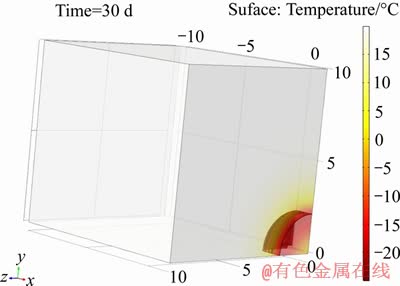
Figure 5 Temperature distribution after freezing for 30 d under -25 ��C brine temperature (Unit: m)
Temperature distribution outside the shield machine was shown in Figure 6. As seen in Figure 6, the minimum temperature outside of the cutterhead, where directly contacts with the condenser pipe, was -24.6 ��C. The condenser pipe in warehouse conducted heat by external steel plate. It can make the temperature outside of the cutterhead at the place of spoke reach at -22.3 ��C and make the temperature at the center of the warehouse farthest from the condenser pipe reach at -20 ��C.
The temperature outside of the cutterhead surface and brine changed over time, as shown in Figure 7. From Figure 7, there was an approximately same cooling trend between the temperature outside of the cutterhead surface and brine. During initial period of freezing, the temperature difference was about 2 ��C. With the brine temperature decreasing, the temperature difference increases slowly. In the mid stage of the freezing, the temperature difference dropped off with the decrease of the temperature-lowering load.

Figure 6 Temperature distribution outside of shield machine after freezing 30 d under -25 ��C brine (Unit: m)

Figure 7 Average temperature of brine and outside cutterhead
The frozen curtain shape after freezing in 30 d and 50 d were provided in Figures 8 and 9. The temperature of frozen soil was -0.5 ��C.
From Figures 8 and 9, the frozen wall expanded forward and was not affected by the uneven temperature of the outer surface of the cutterhead. The frozen wall at the center of the cutterhead was the thickest, while the frozen wall decreased smoothly with the increasing radius. Because thermal load distributed only in front of the cutterhead center, the thermal load ahead and sides increased gradually with the increasing radius. Thus, the thickness of the frozen wall was less than that of cutterhead center.
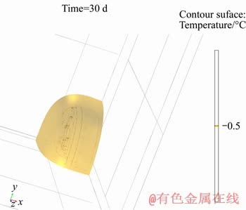
Figure 8 Frozen curtain shape in front of shield machine after freezing 30 d under -25 ��C brine

Figure 9 Frozen curtain shape in front of shield machine after freezing 50 d under -25 ��C brine
As shown in Figure 10, the frozen wall thickness at the place of cutter 1 and cutter 2 at the top left of the shield machine in finite model was extracted. The frozen wall thickness under different brine temperature was shown in Tables 2-4.
The thickness and average temperature of frozen wall back of the cutterhead under different freezing time was shown in Table 5.
3.2 Stress analysis of frozen wall during process of opening warehouse and changing cutterhead
3.2.1 Finite element model
The force on the frozen wall was calculated when the warehouse was opened successively for tool repair after the formation of the frozen wall. As shown in Figures 9 and 10, cutter 1 was farther from the center of cutterhead than cutter 2 and had higher risk than cutter 2. So, it needs to check out the thickness and strength of the frozen wall at the position of cutter 1. The finite model by using stratum structure method was established to regard the lining and the stratum as a whole. The internal forces of the lining and stratum respectively were calculated on the premise of meeting the deformation coordination conditions, and the stability of the stratum was checked and the design of the component section was carried out based on it. The finite model was shown in Figure 11. The finite element model was meshed by tetrahedron mesh method, as shown in Figure 12.

Figure 10 Location diagram of frozen wall position
3.2.2 Boundary condition and calculating parameter
The elasticity modulus of frozen soil was 300 MPa , Poisson ratio was 0.23, density was 1890 kg/m3. The elasticity modulus of unfrozen soil was 100 MPa, Poisson ratio was 0.3 and density was 1890 kg/m3. The thickness of frozen wall was 0.5 m and the average temperature of frozen wall was -10 ��C. The strength of frozen soil was subject to the strength of the clay under the average temperature of -10 ��C.
Table 2 Thickness and average temperature of cutter 1 and cutter 2 after freezing 30 d
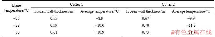
Table 3 Thickness and average temperature of cutter 1 and cutter 2 after freezing 40 d
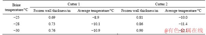
Table 4 Thickness and average temperature of cutter 1 and cutter 2 after freezing 50 d

Table 5 Thickness and average temperature of frozen wall back of cutterhead under different freezing time


Figure 11 Stress analysis model of frozen wall (Unit: m)

Figure 12 Stress analysis model grid map of frozen wall (Unit: m)
The top of the model was set as a free boundary, four sides were roller-bearing boundary the bottom of the model was a fixed constraint. When the cutter was replaced, a part of frozen soil will be excavated. The depth of frozen soil excavation was taken as 0.08 m, and the frozen soil after excavation was exposed, which was taken as a free boundary.
The process of calculation was divided into two steps. The first step was to turn on the gravity option to calculate the stress and displacement of frozen soil and unfrozen soil under given boundary conditions. The second step was to extract only the stress calculated in the first step and apply it to the model without extracting displacement for recalculation, and then the long-term consolidation settlement of soil under load can be ignored.
5.2.3 Analysis of calculation results
The Von Mises equivalent stress, first principal stress and third principal stress of frozen soil under given parameter were shown in Figures 13-15.

Figure 13 Mises equivalent stress nephogram

Figure 14 First principal stress nephogram (tensile stress)

Figure 15 Third principal stress nephogram (pressure stress)
From Figures 13-15, when changing the cutter, the frozen wall nearby the cutter bore large tensile and compressive stress. Compared the maximum tensile stress and compressive stress of the most dangerous section to tensile strength, compressive strength of frozen soil, as seen in Table 6, the tensile safety factor and compressive safety factor were both greater than 2. Therefore, the thickness, strength and stability of the frozen wall can meet the maintenance requirements of shield machine.
Table 6 Calculation table of safety factor in most dangerous section

4 Conclusions and discussion
After the shield machine was reformed to have the function of freezing, it had the advantages of saving working hours, reasonable design, high practical value and wide application. According to the shield construction of the Huanxi Power Tunnel, the three-dimensional temperature field analysis and the force analysis of the frozen wall were carried out. It can be concluded that:
1) Due to the better thermal conductivity of the condenser pipe, welding special-shaped condenser pipe on the spoke board and cutter board can make the outer surface of cutterhead form to a hypothermal condenser pipe. The cooling trend between outer surface of the cutterhead and brine is the same. During initial period of freezing, the temperature difference is about 2 ��C. With the brine temperature decreasing, the temperature difference increases slowly. In the midstage of the freezing, the temperature difference drops off with the decrease of the temperature-lowering load.
2) The frozen wall at the center of the cutterhead is the thickest, while the frozen wall decreases smoothly with the increasing radius.
3) The frozen wall thickness and average temperature were calculated in different freezing time under different brine temperature (-25 ��C, -28 ��C and -30 ��C). By reducing the average temperature of frozen soil, the thickness and stability of frozen wall can be increased under the same freezing time. The temperature of brine decreases from -25 ��C to -30 ��C, the thickness of frozen wall increases by 0.06-0.09 m, and the average temperature of frozen wall decreases by about 2 ��C.
4) Analyzing the frozen wall stress under 0.5 m thickness and -10 ��C average temperature, the tensile safety factor and compressive safety factor are both greater than 2 at the most dangerous position, which can meet the strength and stability requirements for maintaining of the shield machine.
5) Analyzing the frozen wall under 0.5 m thickness and -10 ��C average temperature, to meet the excavation requirements in 30 d, the brine temperature should under -28 ��C.
References
[1] EMRE A, HANIFI C. Empirical modeling for predicting excavation performance of EPB TBM based on soil properties [J]. Tunnelling and Underground Space Technology Incorporating Trenchless Technology Research, 2018, 71: 340-353. DOI: 10.1016/j.tust.2017.09.016.
[2] ZHOU Hui, GAO Yang, ZHANG Chuan-qing, YANG Fan-jie, HU Ming-ming, LIU Hai-tao, JIANG Yue. A 3D model of coupled hydro-mechanical simulation of double shield TBM excavation [J]. Tunnelling and Underground Space Technology Incorporating Trenchless Technology Research, 2018, 71: 1-14. DOI: 10.1016/j.tust.2017.07.012.
[3] ZHAO J, GONG Q M, EISENSTEN Z. Tunnelling through a frequently changing and mixed ground: A case history in singapore [J]. Tunnelling and Underground Space Technology, 2007, 22(4): 388-400. DOI: 10.1016/j.tust. 2006.10.002.
[4] CHO Jung-Woo, JEON Seo-Kwon, YU Sang-Hwa, CHANG Soo-Ho. Optimum spacing of TBM disc cutters: A numerical simulation using the three-dimensional dynamic fracturing method [J]. Tunnelling and Underground Space Technology, 2010, 25(3): 230-244. DOI: 10.1016/j.tust.2009.11.007.
[5] GERTSCH R, GERTSCH L, ROSTAMI J. Disc cutting tests in colorado red granite:implications for TBM performance prediction [J]. International Journal of Rock Mechanics arltl Mining Sciences, 2007, 44(2): 238-246. DOI: 10.1016/ j.ijrmms.2006.07.007.
[6] HUO Jun-zhou, SUN Wei, CHEN Jing. Optimal disc cutters plane layout design of the full-face rock tunnel boring machine (tbm) based on a multi-objective genetic algorithm [J]. Journal of Mechanical Science and Technology, 2010, 24(2): 521-528. DOI: 10.1007/s12206-009-1220-8.
[7] ROHOLA H, JAMAL R, MARKUS T, JURGEN S. Parametric study of the impacts of various geological and machine parameters on thrust force requirements for operating a single shield TBM in squeezing ground [J]. Tunnelling and Underground Space Technology incorporating Trenchless Technology Research, 2018, 73: 252-260. DOI: 10.1016/j.tust.2017.12.027.
[8] JAFAR H. Development of an empirical model to estimate disc cutter wear for sedimentary and low to medium grade metamorphic rocks [J]. Tunnelling and Underground Space Technology Incorporating Trenchless Technology Research, 2018, 75: 90i-99. DOI: 10.1016/ j.tust.2018.02.009.
[9] EARL M B. DE G, DYLAN S, MAROLO C A, GUY D, LUKAS U A. Large-scale direct shear testing of compacted frozen soil under freezing and thawing conditions [J]. Cold Regions Science and Technology, 2018, 151: 138-147. DOI: 10.1016/j.coldregions.2018.03.011.
[10] WANG Da-yan, WANG Yong-tao, MA Wei, LEI Le-le, WEN�� Zhi. Study on the freezing-induced soil moisture redistribution under the applied high pressure��[J]. Cold Regions Science and Technology,��2018,��145:��135-141.��DOI: 10.1016/j.coldregions.2017.10.012.
[11] AN Ling-shi, LING Xian-zhang, GENG Yong-chang, LI Qiong-lin, ZHANG Feng, ANTONIO B. DEM investigation of particle-scale mechanical properties of frozen soil based on the nonlinear microcontact model incorporating rolling resistance [J]. Mathematical Problems in Engineering, 2018: 2685709. DOI: 10.1155/2018/2685709.
[12] FENG Xiao, GANG S, CHEN, LEROY H J, DUANE D, YANG Zhao-hui. Characterization of the viscoelastic effects of thawed frozen soil on pile by measurement of free response [J]. Cold Regions Science and Technology, 2018, 145: 229-236. DOI: 10.1016/ j.coldregions.2017.09.011.
[13] WANG Tao, ZHOU Guo-qing, JIANG�� Xiong,��WANG�� Jian-zhou. Assessment for the spatial variation characteristics of uncertain thermal parameters for warm frozen soil��[J]. Applied��Thermal��Engineering,��2018,��134:��484-489.��DOI: 10.1016/j.applthermaleng.2018.02.023.
[14] ROMAN JI T. Mechanics of frozen soil [M]. China Science Publishing & Media Ltd. (CSPM), 2016 .
[15] SURIKOV B B. Frozen soil damage mechanics [M]. China Science Publishing & Media Ltd. (CSPM), 2016 .
[16] ANDERSLAND. Frozen ground engineering [M]. China Architecture & Building Press, 2011.
[17] HU Xiang-dong, FANG Tao, ZHANG Luo-yu. Analytical solution to temperature distribution in frozen soil wall with wavy boundaries by single-row- and double-row-piped freezing [J]. Cold Regions Science and Technology, 2018, 145: 208-228. DOI: 10.1016/j.coldregions.2017.10.010.
[18] BRUN B, HA�� H. Underground line U5��Unter den Linden' Berlin, Germany Structural and thermal FE-calculations for ground freezing design [C]// Proceedings of the International Conference on Numerical Simulation of Construction Processes in Geotechnical Engineering for Urban Environment. Bochum, German, 2006: 225-232.
[19] PIMENTELA E, PAPAKONSTANTINOUB S, ANAGNOSTOU G. Numerical interpretation of temperature distributions from three ground freezing applications in urban tunneling [J]. Tunnelling and Underground Space Technology, 2012, 28(1): 57-69. DOI: 10.1016/j.tust.2011.09.005.
[20] PIMENTELA E, SRES A, ANAGNOSTOU G. Large-scale laboratory tests on artificial ground freezing under seepage-flow conditions [J]. Geotechnique, 2012, 62(3): 227-241. DOI: 10.1680/geot.9.P.120.
[21] WANG M S. Tunnel underground engineering technology. [M]. Beijing: China Communications Press. (in Chinese)
[22] WANG Y. Mechanical property analysis of steel pipe-frozen soil composite structure in freeze-sealing pipe roof method [D]. Shanghai: Tongji University. (in Chinese)
[23] ZHANG P, MA B S, ZHAO W. The largest curved pipe roofing tunnel project in the world [C]// Pipelines 2013. Pipelines and Trenchless Construction and Renewals��A Global Perspective. United States: ASCE, 2013: 953�C963.
[24] HU Xiang-dong,HONG Ze-qun,FANG Tao. Analytical solution to steady-state temperature field with typical freezing tube layout employed in freeze-sealing pipe roof method [J]. Tunnelling and Underground Space Technology, 2018, 79: 336-345. DOI: 10.1016/j.tust.2018. 06.014.
[25] HU Xiang-dong, HAN Lei, HAN Yan-guang. Analytical solution to temperature distribution of frozen soil wall by multi-row-piped freezing with the boundary separation method [J]. Applied Thermal Engineering, 2019, 149: 702-711. DOI: 10.1016/j.applthermaleng.2018.12.096.
[26] LI Shuang-yang, ZHANG Ming-yi, PEI Wan-sheng, LAI�� Yuan-ming. Experimental and numerical simulations on heat-water-mechanics interaction mechanism in a freezing soil [J]. Applied Thermal Engineering, 2018,��132:��209-220. DOI: 10.1016/j.applthermaleng.2017.12.061.
[27] FROUGHO,TORABIS R. An application of rock engineering systems for estimating TBM downtimes [J]. Engineering Geology, 2013,157:112-123. DOI: 10.1016/ j.enggeo.2013.02.003.
[28] GALLOJ,PEREZ-ACEBOH.Performancemodelformicro tunnellingboringmachines(MTBM) [J]. Informes de la Construccion, 2017,69:e203. DOI: 10.3989/id55211.
(Edited by HE Yun-bin)
���ĵ���
�ܹ����䶳���̻����������䶳Ч������ģ���о�
ժҪ��Ϊ��ʵ�ֳ�ѹ������ҵ�������һ�־��ж��Ṧ�ܵĶܹ���������������䶳���̵ĸ��췽���ͻ���ά���������Ի������������ܹ�ʩ��Ϊ�����Ըù����䶳���̽�������ֵ�������������������ˮ�¶�Ϊ-25 ��Cʱ������30 d�����Ķ���ں�ɴ�0.67 m������ƽ���¶Ƚ���-9.9 ��C������ˮ�¶�Ϊ-30 ��Cʱ������50 d����ں�ɴ�1.01 m��ƽ���¶Ƚ���-12.4 ��C�Զ���ں��Ϊ0.5 m��ƽ���¶�Ϊ-10 ��C��Ϊ��������ָ��ʱ����ˮ�¶�Ӧ����-28 ��C��������30 d�Ŀ���Ҫ��ͨ����0.5 m��-10 ��Cƽ���¶��µĶ���ڽ���Ӧ�������ó�����Σ��λ�õĿ�������ѹ��ȫϵ��������2������ܹ�ʩ������Ҫ��
�ؼ��ʣ��ܹ������䶳ʩ�����䶳���̣�����ά��������Ԫ����
Foundation item: Project(2014FJ1002) supported by the Science and Technology Major Project of Hunan Province, China; Project(2012AA041803) supported by National High Technology Research and Development Program of China
Received date: 2019-12-17; Accepted date: 2020-03-17
Corresponding author: XIA Yi-min, PhD, Professor; Tel: +86-731-88879351; E-mail: xiaymj@csu.edu.cn; ORCID:0000-0001-6174- 0377.

