Trans. Nonferrous Met. Soc. China 22(2012) s21-s26
Influence of tool parameters on internal voids in cross wedge rolling of aluminum alloy parts
JIA Zhi, ZHOU Jie, JI Jin-jin, YU Ying-yan, XIAO Chuan
School of Materials Science and Engineering, Chongqing University, Chongqing 400044, China
Received 9 July 2012; accepted 3 August 2012
Abstract: The internal void of cross wedge rolling (CWR) part can be treated as porous material due to their similar physical property and deformation characteristics. Aiming at the CWR process of aluminum alloy 7075 workpiece, the numerical simulation model for internal void was established by means of the rigid-plastic FEM method for the porous material. The relative density was used to research the influence of three primary parameters on the internal void in CWR process, including the forming angle ��1, the stretching angle �� and the area reduction ��A. The experimental results show that the expansion of internal void occurs in the stretching zone, and the knifing zone just has a little influence on it. The stretching angle has a great influence on the internal void, while the area reduction has a small influence on it. The size of internal voids decreases with the increase of area reduction, stretching angle and forming angle. When designing the CWR tool geometry and operating conditions, to prevent the internal void, the area reduction is suggested to be 55%-65%, the stretching angle to be 8��-10��, and the forming angle to be 29��-32��.
Key words: 7075 aluminum alloy; porous material; cross wedge rolling; internal void; relative density
1 Introduction
Presently, aluminum alloy has been widely used in aerospace, aviation, military and automotive industries. This tendency is caused by the fact that the use of them can reduce the mass and save the energy [1-4]. The cross wedge rolling (WR) process belongs to advanced method of forming aluminum alloy part. But most of the research about CWR usually focused on the steel, and few of those are applied to the aluminum alloy [5].
The cross wedge rolling is a new method to make metal plastic deforming by using a pair of co-rotating parallel rollers with external surface of wedge-type scab rolling metal in the cross feed field [6]. The simplified model is shown in Fig. 1. CWR has many advantages, such as high productivity, saving material and energy, high precision product, and good working conditions [7, 8]. Despite these advantages, CWR is not widely used throughout the manufacturing community. One of the primary problem is the difficult tool design because of internal defects (voids and cracks) encountered in the CWR process.
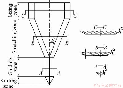
Fig. 1 Schematic diagram of simplified model of CWR tool structure
There is no complete agreement on the primary mechanism of internal voids. LI et al [9,10] summarized the primary explanations as follows: 1) large tensile stresses in the central portion of workpiece; 2) excessive shear stresses induced by the knifing action of the forming dies; and 3) low cycle fatigue that develops during the rolling process.
It is very important to establish the critical conditions under which the internal void will not occur in the CWR process. Many researchers have paid much attentions to the internal void with physical and numerical simulation methods, and all of them use the plastic mechanics method to analyze and predict the internal void [11-16]. But this method cannot directly observe the generation process of the internal void, let alone obtain the critical conditions.
In this study, a 3D simulation model is developed to research the general evolution of internal voids during cross wedge rolling of aluminum alloy parts. Based on the property of porous material, a new method is presented to analyze the forming process of internal void. According to the density fluctuation of the porous material, the forming mechanism of void is analyzed, and the impacts of the various tool parameters upon the relative density are discussed.
2 Finite element model
In this research, the internal void of CWR part can be treated as porous material due to their similar physical property and deformation characteristics. Now, the porous material is seen as compressible continuous body. The model of porous material is expressed as [17]:
 (1)
(1)
where A=2+R2, B=1-A/3=2R2-1, R is the relative density; J1�� is the second invariants of the stress deviator; J1 is the first invariant of stress tensor; YR is the yield stress of porous material; Y0 is the yield stress of solid material.
In order to further understand the reasons of the defects, the finite element method was employed to simulate the cross wedge rolling process. Because of the symmetry of CWR tool structure, only half symmetry model was selected. The model consists of a billet, two tools and two guide plates. The center of workpiece is set to the porous material with the relative density of 0.5, and the rest area is 1.
The deformation of rolling axial part with large diameter by cross-wedge rolling has not only a radial compression and an axial extension, but also a transversal expansion. Therefore, when setting up the finite element model, many factors need to be considered, which are non-linear in material (between stress and strain), in geometry (between strain and displacement) and under boundary condition, etc [18].
In order to reduce CPU processing time and eliminate the effect of irrelevant factors, the following assumptions have been developed.
1) Due to the negligible elastic deformation of tools and guide plates, the tools and guided plates are defined as rigid bodies.
2) In the simulation, the workpiece material is aluminum alloy 7075. It is assumed that the material is isotropic and that the yielding behaviour follows the von Mises yield criterion. The flow stress, on which plastic deformation occurs in the metal, is influenced by the equivalent strain, equivalent strain rate, and temperature [7].
3) The friction coefficient on the material�Ctool interface is constant. The frictional force in the constant shear model is defined by:
fs=mk (2)
where fs is the frictional stress, k is the shear yield stress, m is the friction coefficient. Equation (2) states that the friction is a function of yield stress of the deforming body.
4) It is assumed that the friction between guiding plate and workpiece is ignored.
5) The rotational velocity of the roller is constant during the rolling process.
6) Higher mesh density can increase the accuracy and resolution of geometry. However, the calculating time required for solving the problem is increased as the number of nodes increases. Thus, in this finite element model, it is desirable to have a relatively larger number of small elements in the regions where the material is defined as porous material.
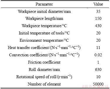
Simulations were performed by applying equal and same direction velocities to the forming tools in the horizontal (x) direction. In the numerical analyses, the workpiece was left unconstrained and the forming tools were held in the vertical (y) and out-of-plane (z) directions. The finite element model for the two-roll CWR is shown in Fig. 2, and the main rolling conditions and the information of billet are listed in Table 1.
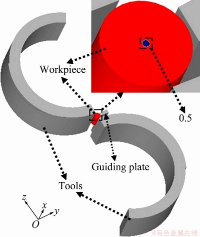
Fig. 2 Finite element model of CWR
Table 1 Main parameters of rolling of aluminum alloy 7075
In order to verify the effectiveness of the FEM model, two simulations were carried out. Simulation 1 used the FEM model mentioned above, while in simulation 2, the plastic material was used to replace the porous material in workpiece. Through detailed comparison between the two simulation results, it was found that the deformation of workpiece during this two roll processes were identical. This means that the plastic material and porous material have similar physical property and deformation characteristics, and the internal void of CWR part can be treated as porous material under the given model. So the FEM model is effective and reliable.
3 Experimental
Although the mechanisms of the void formation are driven by the localized stress and strain of the central portion of the workpiece, the formation of internal void is ultimately determined by the CWR tool geometry and operating conditions [19]. For the final geometry of the workpiece, the forming angle ��, stretching angle ��, and area reduction ��A are the most important parameters in the CWR process. These parameters not only determine the level of plastic deformation experienced by the workpiece, but also play an important role in determining whether the internal defects will occur.
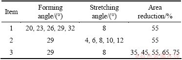
Subsequently, in order to avoid the emergence of potential defects in the process of CWR, according to the theoretical research and practical experience, the range of forming angle ��, stretching angle �� and area reduction ��A should be ascertained. Accord to the research of steel material, the range of these parameters is defined. The range of forming angle �� is 18��-34��, the stretching angle �� is 4��-12��, and the area reduction ��A is 35%-75% [19]. The simulation is divided into three groups and the parameters are listed in Table 2.
Table 2 Calculating parameters in simulation
4 Results and discussion
The initial void first generates in the center of workpiece, and then expands to the surrounding area during CWR process. So the central points at the middle section of workpiece were used to measure the density change with different area reductions ��A, forming angle �� and stretching angle ��. In general, for greater density after CWR process, the size of internal void is smaller.
4.1 Effect of area reduction
The area reduction ��A is a measure of the amount of the radial reduction of the workpiece. The larger the value of ��A, the larger the radial compression experiences, and the longer the overall length of the workpiece. Figure 3 shows the relationship between area reduction and relative density under the condition of ��=29�� and ��=8��. It can be seen from Fig. 3 that the density rises with the increase of area reduction. Therefore, smaller area reduction can accelerate the formation and enlarge the size of internal voids. This is consistent with the results by HU et al [19]. The reason is that when the area reduction is too small (��A=35%), the deformation occurs mainly on the surface of the workpiece, and the deformation in the centre is extremely difficult, which leads to the accumulation of larger tension at the centre of workpiece. But when ��A=75%, the value of the density increases rapidly, because of the fracture caused by the plastic instability of workpiece. So, when it comes to large area reduction (greater than 75%), the multiple-stage cross wedge rolling with different tools is necessary.
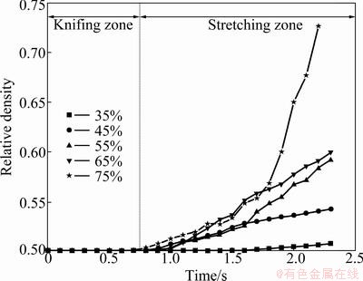
Fig. 3 Relationship between area reduction and relative density
It can be found from Fig. 3 that the variation trend of void size is the most significant when ��A is 65%. When the area reduction is ranged from 55% to 65%, the relative density after rolling is almost the same. So, the area reduction is suggested to be between 55% and 65%.
4.2 Effect of stretching angle
The stretching angle �� is a primary tool parameter in the CWR process. It determines the degree of axial deformation experienced by the workpiece. Larger stretching angle of the tool leads to more elongation of the workpiece. In this section, the relationship between stretching angle and density was investigated. Figure 4 shows the relationship between the stretching angle and relative density under the condition of ��=29�� and ��A=55%. It can be seen from Fig. 4 that when the stretching angle �� is 4��-10��, the density increases with the increase of stretching angle, while when �� is 12��, the minimum density is obtained. The reasons for this trend can be explained as follows. When the stretching angle is very small (��=4��), the amount of the workpiece rotation increases, and this leads to the accumulation of larger tension in the center of workpiece, which will make void growth. When the stretching angle is too large (��=12��), the deformation of workpiece is very severe during the CWR process, which also can accumulate larger tension in the centre of the workpiece.
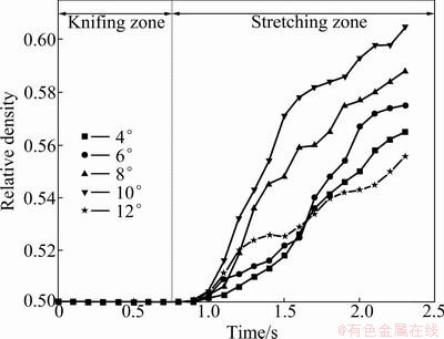
Fig. 4 Relationship between stretching angle and relative density
From Fig. 4, a significant difference in the void size is observed at ��=10��. When the stretching angle increases from 8�� to 10��, the density increases by about 28.1%. It is helpful to prevent the internal void. Hence, when the area reduction is in the range of 55%-65%, the stretching angle is suggested to be between 8�� and 10��.
4.3 Effect of forming angle
The forming angle �� controls the size of the contact area between the tools and the workpiece. In these zones, a relative small forming angle can increase the contact area and produce a more localized plastic deformation. In the stretching and sizing zone, the forming angle establishes the geometry of workpiece such that a larger value leads to a larger draft angle [9]. Figure 5 shows the relationship between the forming angle and relative density under the condition of ��=8�� and ��A=55%. It can be seen from Fig. 5 that the density increases with the increase of forming angle. Therefore, smaller forming angle can accelerate the formation and enlarge the size of internal voids. This phenomenon results from the decrease of the contact area and the workpiece axial deformation with the increase of forming angle. This trend leads to the decrease of tension in the central part at the same time.
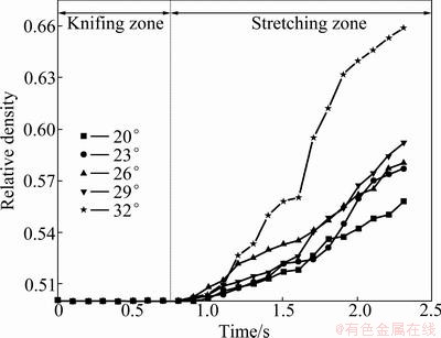
Fig. 5 Relationship between forming angle and relative density
It can also be seen from Fig. 5 that the maximum density is obtained when the forming angle is 32��. However, when the forming angle is too large (greater than 40��), the workpiece tends to experiment necking or fracture [20]. For this reason, when the value of area reduction is 55%-65%, the forming angle is suggested to be between 29��and 32��. Due to the reasons mentioned above and the range of density with the change of forming angle, it can be concluded that the stretching angle has a great influence on the internal void, while the area reduction has a small influence on it.
After many times of trials, the same law is found from Figs. 3, 4 and 5. The density can hardly fluctuate in the knifing zone, and then it increases rapidly in the stretching zone and finally reaches the maximum values. This means that the expansion of internal void occurs in the stretching zone, and the knifing zone just has a little influence on it. This is because large tensile stresses are the primary factor for initiating internal defects. If the tensile stresses of workpiece are large enough in the knifing zone, they can cause cracks in the center. As the workpiece rotates, the compression and tension regions alternate every 90��. Depending on this cyclic loading, the cracks can merge to create macroscopic void after several rotations of workpiece in stretching zone.
5 Conclusions
1) The porous material is used in this simulation, and the density during CWR process is applied to predict the internal void. Large density after CWR process means that the size of internal void is relative small.
2) During the forming process, the spread of internal void occurs in stretching zone, and the knifing zone just has a little influence on it. As for the process parameters, the size of internal voids decreases with the increases of area reduction, stretching angle and forming angle. The stretching angle has a great influence on the internal void, while the area reduction has a small influence.
3) In order to prevent the internal void of workpiece when design the CWR tool geometry and operating conditions, the area reduction is suggested to be between 55% and 65%, when the stretching angle is 8��-10��, and the forming angle is 29��-32��.
References
[1] LI Yi, WANG Zhong-jin. Finite element analysis of stiffness and static dent resistance of aluminum alloy double-curved panel in viscous pressure forming [J]. Transactions of Nonferrous Metals Society of China, 2009, 19(s1): s312-s317.
[2] CAI Zhen-bing, ZHU Min-hao, LIN Xiu-zhou. Friction and wear of 7075 aluminum alloy induced by torsional fretting [J]. Transactions of Nonferrous Metals Society of China, 2010, 20(3): 371-376.
[3] ZHANG Da-wei, YANG He, SUN Zhi-chao. Finite element simulation of aluminum alloy cross valve forming by multi-way loading [J]. Transactions of Nonferrous Metals Society of China, 2010, 20(6): 1059-1066.
[4] QUAN Guo-zheng, LIU Ke-wei, ZHOU Jie, CHEN Bin. Dynamic softening behaviors of 7075 aluminum alloy [J]. Transactions of Nonferrous Metals Society of China, 2009, 19(S3): s537-s541.
[5] PATER Z, GONTARZ A, TOFIL A. Analysis of the cross-wedge rolling process of toothed shafts made from 2618 aluminum alloy [J]. Journal of Shanghai Jiao Tong University: Science, 2011, 16(2): 162- 166.
[6] QIANG Ying-fu, SONG Pan-bo. Analysis on temperature distribution in cross wedge rolling process with finite element method [J]. Journal of Materials Processing Technology, 2007, 187(12): 392-396.
[7] WANG Min-ting, LI Xue-tong, DU Feng-shan. Analysis of metal forming in two-roll cross wedge rolling process using finite element method [J]. Journal of Iron and Steel Research, International, 2009, 16(1): 38-43.
[8] DONG Y M, LOVELL M, TAGAVI K. Analysis of interfacial slip in cross-wedge rolling: An experimentally verified finite-element model [J]. Journal of Materials Processing Technology, 1998, 80-81: 273-281.
[9] LI Q, LOVELL M R, SLAUGHWER W, TAGAVI K. Investigation of the morphology of internal defects in cross wedge rolling [J]. Journal of Materials Processing Technology, 2002, 125(s1): 248-257.
[10] LI Q, LOVELL M. Cross wedge rolling failure mechanisms and industrial application [J]. International Journal of Advanced Manufacturing Technology, 2008, 37(3-4): 265-278.
[11] LI Q, LOVELL M R. The establishment of a failure criterion in cross wedge rolling [J]. International Journal of Advanced Manufacturing Technology, 2004, 24(3-4): 180-189.
[12] CUI Li-hua, WANG Bao-yu, HU Zheng-huan. Evolution of internal holes in aluminum alloy parts by cross wedge rolling [J]. Journal of University of Science and Technology Beijing, 2012, 34(2): 190-195.
[13] BARTNICKI J, PATER Z. Numerical simulation of three-rolls cross-wedge rolling of hollowed shaft [J]. Journal of Materials Processing Technology, 2005, 164: 1154-1159.
[14] URANKAR S, LOVELL M, MORROW C, LI Q, KAWADA K. Establishment of failure conditions for the cross-wedge rolling of hollow shafts [J]. Journal of Materials Processing Technology, 2006, 177(1-3): 545-549.
[15] PATER Z. A study of cross wedge rolling process [J]. Journal of Materials Processing Technology, 1998, 80: 370-375.
[16] LEE H W, LEE G A, YOON D J, CHOI S, NA K H, HWANG M Y. Optimization of design parameters using a response surface method in a cold cross-wedge rolling [J]. Journal of Materials Processing Technology, 2008, 201(1-3): 112-117.
[17] HUANG Hua-gui, DU Feng-shan, XU Zhi-qiang. FEM analyses on compaction of porosity defects inside heavy forgings during hot forging process [J]. Engineering Mechanics, 2011, 28(9): 245-250.
[18] SHU Xue-dao, LI Chuan-min, ZHAO Jing, HU Zheng-huan. Theoretical and experimental study of varying rule of rolling-moment about cross-wedge rolling [J]. Journal of Materials Processing Technology, 2007, 187: 752-756.
[19] HU Zheng-huan, ZHANG Kang-shen, WANG Bao-yu, SHU Xue-dao, YANG Cui-ping. Formed technology and simulation of parts about the cross wedge rolling [M]. Beijing: Metallurgical Industry Press, 2004: 180-189. (in Chinese)
[20] DONG Y, TAGAVI K A, LOVELL M R. Analysis of interfacial slip in cross-wedge rolling: A numerical and phenomenological investigation [J]. Journal of Materials Processing Technology, 2000, 97(1-3): 44-53.
ģ�߲�����Ш�������Ͻ������ڲ��ն���Ӱ��
�� �ǣ��� �ܣ��������ӯ�࣬Ф ��
�����ѧ ���Ͽ�ѧ�빤��ѧԺ������ 400044
ժ Ҫ��ͨ������Ш�����ڲ��ն�(����)ȱ�ݵ��������ʺ��γ����������ڲ��ն���Ϊ��ײ��ϣ����ö�ײ��ϵĸ���������Ԫ����������7075���Ͻ������ڲ��ն�ȱ�ݵ���ֵģ�͡���������ܶ��о����νǡ�չ���ǡ����������ʶ��ڲ��ն�ȱ�ݵ�Ӱ����ɡ������ʾ���ڲ��ն�����չ��Ҫ������չ���Σ�Ш��ζ�����Ӱ���С��չ������Ӱ���ڲ��ն���������Ҫ���أ������������ʵ�Ӱ���С�����νǡ�չ���ǡ�����������Խ��Խ�������ڲ��ն�ȱ�ݡ���ģ�����ʱ��Ϊ�˷�ֹ���Ͻ��������ƺ�����ڲ��ն�ȱ�ݣ�����������Ӧѡ����55%~65%֮�䣬չ������8��~ 10��֮�䣬���ν���29��~ 32��֮�䡣
�ؼ��ʣ�7075���Ͻ𣻶�ײ��ϣ�Ш�������ڲ��ն�������ܶ�
(Edited by LONG Huai-zhong)
Foundation item: Project (51275543) supported by the National Natural Science Foundation of China; Project (cstc2009aa3012-1) supported by the Key Projects of Chongqing Science and Technology Pran
Corresponding author: ZHOU Jie; Tel: +86-13996399957; E-mail: jiazhi1985@163.com

