
Bending properties and fracture mechanism of
C/C composites with high density preform
ZHANG Ming-yu, SU Zhe-an, LI Jian-li, HUANG Qi-zhong
State Key Laboratory of Powder Metallurgy, Central South University, Changsha 410083, China
Received 30 May 2010; accepted 5 August 2011
Abstract: C/C composites with banded structure pyrocarbon were fabricated by fast chemical vapor infiltration (CVI), with C3H6 as carbon source, N2 as carrier gas, and three-dimensional (3D) 12K PAN-based carbon fabric with high density of 0.94 g/cm3 as preform. Experimental results indicated that the fracture characteristics of C/C composites were closely related to the frequency of high-temperature treatment (HTT) at the break of CVI process. According to the load-displacement curves, C/C composites showed a pseudoplastic fracture after twice of HTT. After three times of HTT, load-displacement curves tended to be stable with a decreasing bending strength at 177.5 MPa. Delamination failure and intrastratal fiber fracture were observed at the cross-section of C/C composites by scanning electronic microscope. Because the content of pyrocarbon and fibers has a different distribution in layers, the C/C composites show different fracture characteristics at various regions, which leads to good toughness and bending strength.
Key words: C/C composites; chemical vapor infiltration (CVI); high density preform; bending properties; fracture mechanism
1 Introduction
Carbon/carbon composites (C/C) are used in high-temperature applications, such as rocket nozzles, heat shields for atmospheric reentry, airplane and F-1 brake pads, and furnace components. C/C composites combine the excellent mechanical properties of composites with high-temperature behavior. The highest thermal and mechanical quality is obtained from chemical vapor infiltration (CVI) [1-2]. The high quality is ensured since composites generally consist of fibers surrounded by pyrocarbon matrix. Because high performance C/C composites are extensively used in the fields of national defense and military projects, few data of mechanical properties were reported [3-9]. Thus few data on C/C composites fabricated by high density three-dimensional (3D) preform were reported [10-11].
This work reports the mechanical characteristics of C/C composites fabricated by rapid chemical vapor infiltrating high density 3D preform. Firstly, the densification of high density 3D preform is carried out with fast CVI process and it is of prime importance to infiltrate the right status of pyrocarbon by adjusting CVI parameters. Secondly, different times of high- temperature treatment were carried out for C/C composites during CVI process. Finally, the mechanical properties of C/C composites were characterized so as to optimize the design of preform structure and fabrication process of C/C composites.
2 Experimental
2.1 Materials preparation
Carbon fiber preform was 12K PAN-based 3D orthogonal carbon fiber weaves with an initial density 0.94 g/cm3 and fiber volume fraction 53.4%. With N2 as carrying gas and C3H6 as carbon source, C/C composites were fabricated by home-made fast CVI furnace. Repeated cycling “CVI-high temperature treatment (HTT)-CVI” was carried out while deposition temperature remained low (900-1 100 °C). At the break of CVI, the materials were heat treated at 2 300 °C for 2 h to relieve the interfacial stress between carbon fibers and pyrocarbon, and then the pyrocarbon shell around the C/C composites was removed by machining process. The densities were measured by Archimedes law.
2.2 Material characterization
The bending strength of C/C composites were investigated by using a CSS-44100 electronic universal testing machine. Based on QJ2099―1993 and GB14452―1991 standards, six effective specimens from each sample with finish size of 55 mm×10 mm×4 mm were tested by three-point bending method with loading rate and span of 1.0 mm/min and 40 mm, respectively. The morphologies of fracture were observed by FEI Nova Nano SEM230 field emission scanning electron microscope (FESEM). The microstructure of pyrocarbon was analyzed using optical microscopy with polarized light (Leica Fe3A).
3 Results and discussion
3.1 Influence of HTT times on bending properties of C/C composites
The banded structures including rough laminar (RL) pyrocarbon and smooth laminar (SL) pyrocarbon were obtained by controlling CVI parameters. SUN et al [12] indicated that different microstructures show distinct fracture mechanism. Besides the effect of bonding strength of fiber/matrix, different pyrocarbon microstructures lead to dissimilar spreading resistance of cracks along the interfaces. As shown in Figs. 1(a) and 1(b), a layer of RL pyrocarbon (the bright part around fibers in Fig. 1(b)) of about 3-5 μm thickness was first deposited around fiber and then SL pyrocarbon. As we know, RL pyrocarbon is a kind of easy graphitization carbon which provides the suitable bonding strength of fiber/pyrocarbon interface. However, SL pyrocarbon is a kind of more difficult graphitization carbon characterized by excellent mechanical property [13]. Thus, this deposited banded structure can keep C/C composites excellent mechanical property while ensuring no brittle fracture after graphitization. At the same time, the strength of fiber/pyrocarbon interface can also be adjusted by HTT times to elevate toughness property.
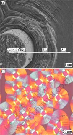
Fig. 1 Structures of pyrocarbon and interface of C/C composites: (a) SEM image; (b) Polarized light microscope image
Figure 2 shows the densities at different stages during the preparation of C/C composites (N=0, 1, 2, 3 indicates HTT times. The densities are measured after N times HTT). As shown in Fig. 2, the density of C/C composites changed unobviously after twice HTT, and CVI became inefficient and the cost increased. The phenomenon of “sealed hole” is likely to appear during the densification of high density 3D preform. The intermediate heat treatment and surface machining can obviously open the sealed holes [14-16]. However, with the density increasing and holes diminishing and disappearing, the growth of density gradually decreased after CVI.
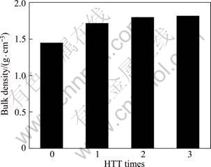
Fig. 2 Effect of HTT times on densities
Figure 3 shows the load-displacement curves of fabricated C/C composites. After HTT, on one hand, the strength of C/C composites decreased due to graphitization. On the other hand, the volume shrinkage promotes the density and bending strength while parts of sealed holes were opened. ZHOU et al [17] considered the ordered arrangement of pyrocarbon atoms almost finished after twice of HTT and the graphitization degree of graphite microcrystalline tended to be stable. As shown in Fig. 3, tubostratic stacking of carbon matrix led to great interface bonding force of matrix/fiber and the characteristic of bending curve (N=0) showed obvious brittle failure. After once HTT, the characteristic of bending curve (N=1) shows pseudoplastic fracture. It is important for HTT to open the sealed holes and then the density experiences a great rise after CVI. During the HTT, the ordered arrangement of graphite microcrystalline and the mismatch of thermal expansion coefficient between carbon fiber and pyrocarbon led to comparatively weak interface bonding force of matrix/fiber and pseudoplastic fracture of C/C composites [18]. After twice of HTT, the graphitization ratio of pyrocarbon was raised and then the fracture stress of C/C composites was lowered. After three times of HTT, the density growth of C/C composites reduced and the contribution of ungraphitized pyrocarbon to bending strength also fell. At the same time, the bonding force between layers declined, and the delamination was observed under bending force.
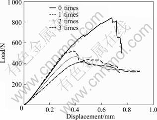
Fig. 3 Effect of HTT times on bending performance
3.2 Bending characteristics and mechanism of C/C composites
The mechanical performance of C/C composites is related not only to the microstructure of pyrocarbon, but also directly to the structure of carbon fiber preform. High HTT times closely influenced the mechanical failure behavior of C/C composites and the fracture characteristics of C/C composites can be divided into two kinds of fracture: interlamination fracture and fracture in X-Y layer.
3.2.1 Characteristics of interlamination fracture
Figure 4 shows the morphology of interlamination fracture of high density 3D orthogonal weaved carbon fiber preform. It can be observed from Fig. 4 that fewer Z-axis carbon fiber appeared and X-Y interlayer of preform was the major region of pyrocarbon deposition. As shown in Fig. 4, the bonding force between layers sharply declined after HTT, which led to delaminating of C/C composites along Z axis under bending force. However, 3D C/C composites have a higher bending strength than 2D C/C composites. The bending strength still reaches 177.5 MPa after three times of HTT.
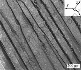
Fig. 4 Morphology of lamination fracture in 3D C/C composites
3.2.2 Fracture characteristics in X―Y layer
During the fabrication of C/C composites with fast CVI, gradient pyrocarbon was formed from both the surfaces of preform to inside and surface of fiber bundle to center in X-Y layer. However, because of high fiber volume fraction of the preform, it is difficult to infiltrate pyrocarbon into nucleus and the sealed holes led to hollow inside. The fabricated C/C composites after three times of HTT were investigated in details as follows.
As shown in Fig. 5, an X-Y layer was chosen to analyze from the delamination of C/C composites in Fig. 4. Figure 5(a) shows the brittle failure of pyrocarbon and peeling of carbon fibers. Figure 5(b) shows the fracture of carbon fibers with pyrocarbon coating. Figure 5(c) shows the morphology of carbon fibers pulled out and fractured. The position of Figs. 5(a), (b) and (c) from surface to center of the layer is marked on Fig. 5(d). Interlaminar surface was deposited sufficient pyrocarbon, while the center of the bundle has the lowest pyrocarbon content due to high fibers volume fraction and fewer hole. Therefore, cyclical arrangement of each fracture surface showed brittle failure of pyrocarbon and debonding of fiber-fracture of fibers coated by pyrocarbon-pulling out of carbon fibers.
3.2.3 Fracture mechanism
In the high density preform, the schematic diagrams shown in Fig. 6 are often characterized by weaving style and different fiber volume fraction or bundle size. And each status in Fig. 6 ccupies corresponding volume percentage. The same case is found in Fig. 7 in the C/C composites. It is conceivable that they play an important role in densification and mechanical properties.
As shown in Fig. 7(a), laminar pyrocarbon orderly grew around each carbon fiber. When bending force was loaded, the applied force between carbon matrix and fibers was transferred to interfacial shear stress. Delamination of fibers and matrix appeared and stepped fracture of adjoining laminar pyrocarbon occurred. Then, the orientation of crack initiation along laminar pyrocarbon deflected. Therefore, the strain of materials was elevated. The fibers were pulled out when the fracturing stress exceeded the interfacial frictional force and fracture toughness of laminar pyrocarbon. On the contrary,fiber breaking or fiber peeling was observed when the fracturing stress was lower than interfacial frictional force and fracture toughness of laminar pyrocarbon [19-21].
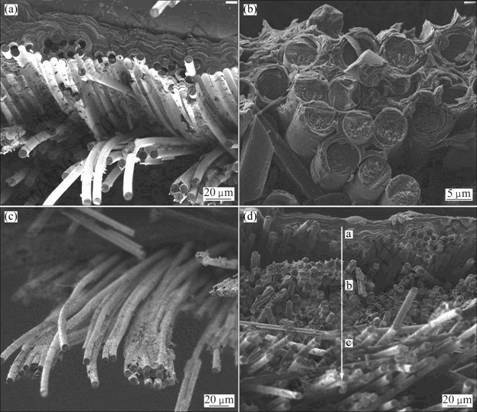
Fig. 5 Fracture characteristics in X―Y layer: (a) Brittle failure; (b) Fracture of coated fibers; (c) Fibers pulled out; (d) Fracture position indication in X―Y layer
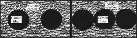
Fig. 6 Schematic diagram of distribution of pyrocarbon with different fibers arrangement: (a) Single fiber or bundle; (b) Closely stacked fibers or bundles
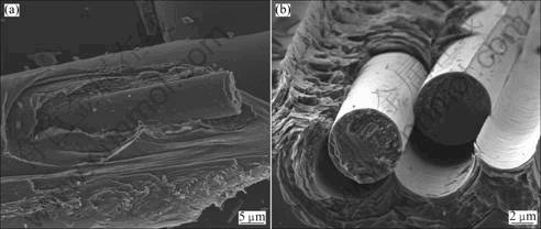
Fig. 7 Micro-morphologies of fracture in two different pack-scabbard structures: (a) Single fiber; (b) Closely stacked fibers
As shown in Fig. 7(b), pyrocarbon is difficult to deposit onto adherent point and inside of the tightly stacked fibers. Thus, single fiber cannot be totally coated by pyrocarbon and just coated as bundle. Then, pyrocarbon is easy to shear failure under lower stress and fibers fail to play a full reinforced role. Therefore, small-tow carbon fiber will be a better way to keep carbon fiber performance for the same fiber volume fraction preform and C/C composites are expected to have better mechanical properties.
4 Conclusions
1) C/C composites were fabricated by CVI with high density 3D orthogonal carbon fiber preform. After HTT at 2 300 °C, the characteristic of bending curve showed pseudoplastic fracture. With increasing the HTT times, the density increasing rate of C/C composites gradually declined and the bending strength successively lowered. After three times of HTT, delamination failure of C/C composites occurred under the action of bending force. Based on experimental results, twice of HTT was suggested.
2) Delamination failure and layer fracture were the main fracture features of C/C composites. The characteristic of the intrastratal fracture showed obvious subregion fracture, and cyclical arrangement of fracture feature was observed.
3) C/C composites fabricated with high density 3D preform can provide an excellent bending property. Fewer Z-axis carbon fibers were considered to be the main reason of delamination failure. Large-tow carbon bundle lowered the efficiency of pyrocarbon infiltration and hollow structure was easy to form which reduces the mechanical properties of C/C composites.
References
[1] SCHMIDT D L. Carbon/carbon composites [J]. SAMPE Journal, 1972, 8(3): 9-19.
[2] KO T H, KUO W S. Effect of carbon fabric type on the mechanical performance of 2D carbon/carbon composites [J]. Polymer Composites, 1998, 19(5): 618-625.
[3] SHI R, LI H J, YANG Z, KANG M K. Textures, interface and fracture of a 1D-C/C prepared by CVD [J] . Acta Metallurgica Sinica, 1996, 9(6): 665-667.
[4] ALY-HASSAN M S, HATTAB H, WAKAYAMA S, WATANABE M, MIYAGAWA K. Comparison of 2D and 3D carbon/carbon composites with respect to damage and fracture resistance [J]. Carbon, 2003, 41: 1069-1078.
[5] CHOLLON G, SIRON O, TAKAHASHI J, YAMAUCHI H, MAEDA K, KOSAKA K. Microstructure and mechanical properties of coal tar pitch-based 2D-C/C composites with a filler addition[J]. Carbon, 2001, 39(13): 2065-2075.
[6] DENK L, HATTA H, MISAWA A, SOMIYA S. Shear fracture of C/C composites with variable stacking sequence [J]. Carbon, 2001, 39(10): 1505-1513.
[7] TARNOPOL’SKII Y M, KULAKOV V L, ARANAUTOV A K. Measurements of shear characteristics of textile composites [J]. Computers & Structures, 2000, 76(1-3): 115-123.
[8] PAILHES J, CAMUS G, LAMON J. A constitutive model for the mechanical behavior of a 3D C/C composite[J]. Mechanics of Materials, 2002, 34(3): 161-177.
[9] ALLIX O, DOMMANGET M, GRATTON M, HEREIL P L. A multiscale approach for the response of a 3D carbon/carbon composite under shock loading [J]. Composites Science and Technology, 2001, 61(3): 409-415.
[10] ZHAO Jian-guo, LI Ke-zhi, LI He-jun. Effects of fiber volume fraction and thermal treatment on the properties of C/C composites [J]. Chinese Journal of Materials Research, 2005, 19(3): 293-298. (in Chinese)
[11] LIAO Xiao-ling, LI He-jun, LI Xin-tao, HOU Dang-she. Flexural behavior of 3D C/C composites [J]. Journal of Materials Engineering, 2006, 6: 54-57. (in Chinese)
[12] SUN Wan-chang, LI He-jun, BAI Rui-cheng, HUANG Yong. Influence of matrix microstructures on mechanical behavior of C/C composites[J]. Journal of Inorganic Materials, 2005, 20(3): 671-676. (in Chinese)
[13] CHEN Teng-fei, GONG Wei-ping, LIU Gen-shan, HUANG Yu-dong, WANG Chao. Influence of carbon matrix type and microstructure on fibre/matrix interfacial strength of C/C composites [J]. Mining and Metallurgical Engineering, 2004, 24(1): 77-79. (in Chinese)
[14] GUELLALI M, OBERACKER R, HOFFMANN M J. Influence of heat treatment on microstructure and mechanical properties of CVI-CFC composites with medium and highly textured pyrocarbon matrices [J]. Composites Science and Technology, 2008, 68: 1115-1121.
[15] GUELLALI M, OBERACKER R, HOFFMANN M J. Influence of heat treatment on microstructure and mechanical properties of highly textured pyrocarbons deposited during CVD at about 1 100 °C and above 2 000 °C [J]. Composites Science and Technology, 2008, 68: 1122-1130.
[16] ZHAO J G, LI K Z, LI H J, WANG C. The influence of thermal gradient on pyrocarbon deposition in carbon/carbon composites during the CVI process [J]. Carbon, 2006, 4: 786-791.
[17] ZHOU Hong-ying, SHU Wu-bing, LIU Jian-jun, CHENG Wen, ZOU Wu, HUANG Han-xing. Study on the effects of high temperature treatment on performance of C/C composites [J]. Journal of Solid Rocket Technology, 2007, 30(1): 68-72. (In Chinese)
[18] SUN Wan-chang, LI He-jun, LU Jin-hua, BAI Rui-cheng, HUANG Yong. Influence of interfaces on mechanical behavior of C/C composites by CLVI processing [J]. Journal of Inorganic Materials, 2005, 20(6): 1457-1462. (in Chinese)
[19] FITZER E, MANOCHA L M. Carbon reinforcements and carbon/carbon composites [M]. Springer, 1998: 190-220.
[20] SUN Le-min, LI He-jun, ZHANG Shou-yang. Fracture characteristics of pitch-based C/C composites [J]. New Carbon Materials, 2001, 16(3): 28-31. (in Chinese)
[21] XIONG Xiang, HUANG Bai-yun, XIAO Peng, WU Feng-qiu. Interlaminar shear strength and fracture mechanism of quasi-3D C/C composites [J]. The Chinese Journal of Nonferrous Metals, 2004, 14(11): 1799-1803. (in Chinese)
高密度预制体制备炭/炭复合材料的
弯曲力学性能与断裂机制
张明瑜,苏哲安,李建立,黄启忠
(中南大学 粉末冶金国家重点实验室,长沙410083)
摘 要:以丙烯作为碳源,氮气作为载气,采用初始密度为0.94 g/cm3三维正交PAN基12 K炭纤维预制体,利用自制的快速CVI炉制备基体热解炭结构为带状结构的C/C复合材料。力学性能测试结果表明,材料的弯曲断裂特征与制备过程中受到的高温热处理次数有关。从载荷-位移曲线来看,当C/C复合材料经过两次热处理时,C/C复合材料呈明显假塑性断裂特征。当C/C复合材料经过三次热处理时,载荷-位移曲线趋于稳定平滑,抗弯强度降低。从C/C复合材料断面的SEM图可以观察到材料断裂可以分为层间断裂和层内断裂,而层内断裂又因热解炭填充密度变化呈明显的分区断裂。由于热解炭和纤维含量在C/C复合材料中分布的差异,材料在不同的区域表现出不同的断裂特征,从而使得材料具备良好的弯曲强度同时具有一定的韧性特征。
关键词: C/C复合材料; 化学气相渗透(CVI); 高密度预制体; 弯曲力学性能; 断裂机制
(Edited by YUAN Sai-qian)
Foundation item: Project (50802115) supported by the National Natural Science Foundation of China; Project (2011CB605801) supported by the National Basic Research Program of China
Corresponding author: ZHANG Ming-yu; Tel: +86-731-88877671; E-mail: zhangmingyu@csu.edu.cn
DOI: 10.1016/S1003-6326(11)60933-3

