Trans. Nonferrous Met. Soc. China 31(2021) 3452-3468
Microstructure evolution of 55Ni-23Cr-13Co nickel-based superalloy during high-temperature cyclic deformation
Kai-meng WANG1,2, Hong-yang JING1,2, Lian-yong XU1,2, Lei ZHAO1,2, Yong-dian HAN1,2, Hai-zhou LI1,2, Kai SONG1,2
1.School of Materials Science and Engineering, Tianjin University, Tianjin 300350, China;
2.Tianjin Key Laboratory of Advanced Joining Technology, Tianjin 300350, China
Received 1April 2021; accepted 28 August 2021
Abstract:
he cyclic deformation behaviorand microstructure evolution of the 55Ni-23Cr-13Co nickel-based superalloy were studied at 750 °C under the strain amplitudes from 0.35% to 0.6%. Coffin-Manson-Basquin and Smith-Watson-Topper relationships were employed, which satisfactorily predicted the fatigue life of the alloy under various strain amplitudes. The superalloy showed an initial cyclic hardening as a result of the interaction between the dislocations and the precipitates, and following cyclic softening behavior mainly due to the shearing of the γ′ phase by dislocations and dislocations recovery under all strain amplitudes. Microstructure analyses showed that the M23C6 carbides exhibited a continuous-chain distribution at lower strain amplitudes, while they showed a discontinuous distribution at higher strain amplitudes. As the strain amplitude increased, the size of the γ′ phase decreased as the consequence of repeated shearing by dislocations.Fracture mechanisms were analyzed. Under higher strain amplitudes, cavities preferred to form around grain boundaries.
Key words:
nickel-based superalloy; microstructure; low cycle fatigue; precipitate;
1 Introduction
The excellent corrosion resistance and mechanical properties of Ni-based superalloyshave prompted their wide application in elevated temperature applications, such as turbine blades and steam boiler tubes. Many nickel-based superalloys have been developed or modified in recent years, such as Inconel 617 [1,2], Inconel 718 [3], and Inconel 740/740H/750 [4-6]. Inconel 750H is a potential candidate for advanced ultra-supercritical (A-USC) power plants, exhibiting good high-temperature tensile properties and oxidation resistance [7]. As a component of power plants, it is subjected to the traditional start-operation-stop cycle, temperature fluctuations, and steam pressure [8-10]. The start-up and shut-down cycles produce cyclic thermal stress, accumulate fatigue damage at high temperatures, and eventually accentuate the problems of these in-served components, such as turbine blades and steam boiler tubes. Therefore, the lowcycle fatigue (LCF) properties of superalloys need to be fully understood to achieve the safe and reliable operation of these components at elevated temperatures.
Considerable researches have been carried out on the fatigue behavior of Ni-based superalloys, such as low/high cycle fatigue behavior [11-13], fatigue crack behavior [14], and creep-fatigue behavior [15]. Cyclic deformation is a type of plastic deformation that includes ratchetingdeformation [16], Masing/non-Masing behavior [17,18] and cyclic hardening/softening behavior.Qualitative and quantitative studies have discussed the reasons for the cyclic softening or hardening of Ni-based superalloys at hightemperatures. Cyclic hardening/softening behavior is related to the precipitates in the superalloy. The fatigue property of a Ni-23Cr-7W alloy and the effects of carbides precipitating after aging at high temperatures have been investigated [19]; non-aged alloys with fine carbides exhibited remarkable cyclic hardening, while aged alloys with coarse carbides exhibited slight cyclic hardening. The cyclic stress responses and strain life relationships of Inconel 617 alloy have been analyzed [20]; continuous cyclic hardening was found to arise from the interaction between the multiple dislocations and the fine M23C6 carbides. The initial cyclic softening behavior of a nickel-based single-crystal superalloy [21] was attributed tothe dissolution of γ′ precipitates, dislocation annihilation, and the formation of interfacial dislocation networks. Cyclic hardening was caused by dislocation entanglement in the matrix. The γ′ rafting effect decreased the hardening influence on the γ′ precipitates, leading to a reduction in the LCF lifespan of the directionally solidified Ni-based superalloy [22]. The softening behavior increased with increasing rafting rates. Chemical vapor deposition-grown Ni alloy with large grains containing ultrafine (UF)/nano twins and UF grains were studied at a cyclic stress ratio of R=0.05 [23]; massive detwinning leads to the softening effect and interactions between the dislocations and the twinning grain boundaries lead to the hardening behavior. Due to the massive detwinning behavior under cyclic deformation, an energy criterion was established to predict the softening effect. The cyclic stress response of a 720Li Ni-based superalloy was studied [24], dislocation–dislocation interactions were found to be responsible for the cyclic hardening and precipitate shearing caused cyclic softening. In the R104 Ni-based superalloy at high temperatures [25], cyclic softening was the result of non-planar deformation bands. Combined with LCF test data, a Ni-based superalloy exhibited both the cyclic hardening and cyclic softening behaviors [26]. It was found that softening was due to the disorder of the γ′ phase, as a result of dislocations cutting into or across the γ′ precipitates, and hardening was caused by inhomogeneous deformation. Above all, cyclic hardening was corresponding to the interactions between the dislocations and fine precipitates, and was also caused by the formation of dislocation networks. Thus, cyclic softening was related to the detwinning behaviors, non-planar deformation bands, andγ′ phase sheared by dislocations and slip bands.
In this study, the LCF tests of the Inconel 750H superalloy were conducted over a wide range of the strain amplitudes at 750 °C. The cyclic softening and Masing behavior related to microstructure deformation were discussed. Detailed microstructures and fracture characteristics were analyzed in order to explore the LCF behavior of the Ni-based superalloy in fatigue tests.
2 Experimental
2.1 Materials
The Inconel 750H superalloy studied in this work is a potential material for manufacturing steam boiler tubes of A-USC thermal power plants. The nominal composition of the Inconel 750H superalloy in mass fraction (wt.%) is shown in Table 1. The material was machined from the pipe with an outer and an inner diameter of 44.5 and 34.5 mm, respectively. The schematic diagram of the LCF test samples is shown in Fig. 1(a). The microstructure of the as-received superalloy is presented in Fig. 1(b). The austenite grain in the raw material varies in size from 50 to 200 μm. Several twinning grain boundaries are visible inside the austenitic grains.
Transmission electron microscopy (TEM, Tecnai G2 F30) observation was performed to analyze the deformed microstructures and precipitates of the fatigued specimens. Energy dispersive spectroscopy (EDS) was used to detectthe composition of the precipitate. Electron back-scatter diffraction (EBSD) characterization was conducted to obtain the orientation and the deformation information. The EBSD samples were obtained through electrolytic corrosion performed for 15 s in a solution containing 5vol.% HClO4 and 95 vol.% alcohol under a constant voltage of 30 V. EBSD scans were performed with a field emission gun scanning electron microscope operating at 20 kV with the step of 2 μm.
Table 1 Chemical composition of non-deformed Inconel 750H superalloy(wt.%)


Fig. 1 Schematic diagram LCF tests samples (a) and microstructure of raw material(b)
2.2 Experimental conditions
The LCF tests were performed using a computer-controlled electronic fatigue testing system. The deformation of the cyclic specimens during the tests was recorded using an extensor- meter. The high-temperature environment was provided by a resistance furnace and the temperature was maintained through closed-loop control. The deviation of the controlled temperature was±2 °C. The fatigue samples were all taken from the longitudinal axial direction of the as-stated material. The samples used in the fatigue tests were machined into cylindrical specimens with a gage length of 20 mm and a gage diameter of 6.0 mm, as shown in Fig. 1(a). The LCF tests were carried out in the manner of total strain control with an R ratio of -1. The loading waveform was a completely symmetric triangular wave and the strain amplitudes were 0.35%, 0.4%, 0.5%, and 0.6%. All the LCF tests were conducted at 750 °C, and the loading rate was set to 1.0×10⁻³ s-1. The cyclic loading was applied after the specimens were maintained at 750 °C for at least 30 min to ensure that the temperature of the specimens was homogeneous.
3 Results
3.1 Cyclic stress response
The relationships between the stress and the number of cycles under different strains are shown in Fig. 2(a). The cyclic behaviors of the superalloy correspond with the variations in the strain. Continuous cyclic softening occurs after a slight hardening in the strain from 0.35% to 0.6%. Peak hardening deformation occurs at 10-30 cycles, and cyclic softening occurs in the subsequent cycles. The normalization of cyclic stress response curves under various strains is plotted in Fig. 2(b). Peak hardening behavior can be obviously detected under all tested conditions. As the strain increases, the fraction of initial hardening behavior increases. The LCF test results are shown in Table 2, where △σ/2 is the stress,△εt/2 is the total strain, △εe/2 is the elastic strain,△εp/2 is the plastic strain,Nf is the number of cycles to failure, and E is elastic modulus. The LCF life increases with a decrease in the strain. As shown in Table2, the cycle stress decreases and the number of cycles increases with the decreasing strain. The reduction in the LCF life of the superalloy corresponds to the increasing proportion of the plastic strain in the total strain.
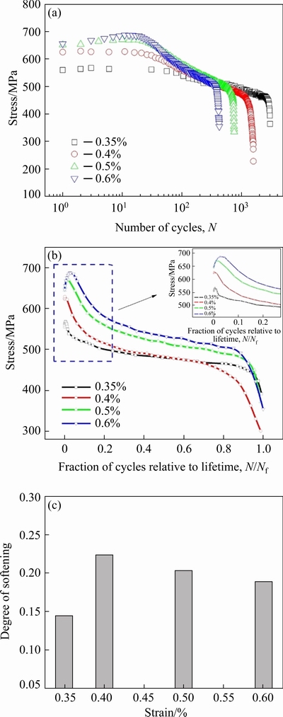
Fig. 2 Cyclic stress versus number of cycles(a), cyclic stress versus fraction of cycles relative lifetime(b), and degree of softening under different strains(c) of 750H superalloy
Thus, pronounced initial cyclic hardening is followed by continuous softening at all strains in the superalloy. The degree of softening Rsis calculated using the following formula [27]:
 (1)
(1)
Where σ0.5lis the stress of the half-life andσ1 is the stress of the first cycle. The values of the degree of softening at the mid-life are presented in Table 3 for all the studied conditions. Figure 2(c) shows the relationship between the degree of softening and the strain. The cyclic softening level of the superalloy increases when the applied strain increases from 0.35% to 0.4% and then decreases when the strain increases from 0.4% to 0.6%.
Table 2 LCF data of Inconel 750H superalloy at different strains

Table 3 Degree of softening value of Inconel 750H superalloy at various strains

3.2 Cyclic strain-stress and Masing behavior
The hysteresis loop describes the stress-strain response during the fatigue process. A stable loop is considered as the hysteresis loop related to 0.5Nf (mid-life) [28]. The plastic strain range can be obtained through the width of the hysteresis loop. The half-life hysteresis loops at various strains are shown in Fig. 3(a). The width of the half-life loops increases as the strain increases from 0.35% to 0.6%. In addition, the peak stress decreases with a decrease in strain.
When the lower points of the stable loops match and all transformed hysteresis loops follow the same loading path, the material is considered to represent the Masing behavior. To study the branching of the hysteresis loops of the material, the envelope half-life curves translated to a common tip of the origin point of the fatigued materials are shown in Fig. 3(b).
At the strain of 0.35%, the plastic strain occupies a much smaller proportion than the elastic strain in the total strain. The percentage of the plastic strain in the total strain gradually increases from 25% to 53% with an increase in the strain from 0.35% to 0.6% (Fig. 3(c)).

Fig. 3 Half-life hysteresis loops at various strains (a), half-cycle hysteresis loops matched compressive tips at origin(b), fractions of plastic strain and elastic strain in total strain at half-life cycle under various strains(c), and relationship between stress and plastic strain at half-life cycle(d) (N is the cycle number)
The cyclic stress-strain behavior of the 750H superalloy at 750 °C is presented in Fig. 3(d). All represented specimens are related to the cyclic stress-strain curve at half-life cycle. The cyclic stress-strain curve can be obtained using the following equation:
 (2)
(2)
wheren′is the cyclic strain-hardening exponent and K′is the cyclic hardening coefficient. A logarithmic plot of the plastic strain versus stress was used to obtain the cyclic strength parameter. Using the linear regression method,K′andn′of the super- alloy were determined to be 862 MPa and 0.09, respectively.
3.3 Life prediction
For the strain-controlled LCF tests, Coffin-Manson-Basquin relationship is used. Fatigue life curve can be expressed by the elastic and plastic strain-life equations, as shown below [10,29]:
 (3)
(3)
whereσ′f,ε′f, b and c are fatigue strength coefficient, fatigue ductility coefficient, fatigue strengthexponent, and fatigue ductility exponent, respectively. The coefficient and exponent can be determined from the fitting results in Fig. 4(a).
To evaluate the fatigue life, considering the product of strain and maximum stress, Smith-Watson-Topper (SWT) model based on stress-straincurves is defined as follows [30,31]:
 (4)
(4)
whereσmax is the maximum stress, andσ′f*,ε′f*, b* and c* are material constants. The parameters of the SWT model can be determined from the fitting results in Fig. 4(b).
As shown in Fig. 4, the R2 is close to 1, which means good fitting results of both Coffin-Manson-Basquin and SWT models. Thus, Coffin-Manson-Basquin and SWT models can well describe the cyclic behavior of the Inconel 750H superalloy.
3.4 Microstructure
Grain size and orientation variations of the studied specimens were characterized through EBSD observations, as illustrated in Fig. 5. The maximum value of texture intensity is 1.8 under all the studied conditions. Therefore, there is no obvious change in the texture. Grain size measurements were conducted using the data of all complete grains in three EBSD maps, which were calculated through measuring the average size of austenite grain. Compared with the as-received state, the grain size decreases when subjected to fatigue loading (Fig. 6).

Fig. 4 Relationship between strain and fatigue life based on Coffin-Masson-Basquinmodel (a)and relationship between product of strain and maximum stress and fatigue life based on SWT model(b)

Fig. 5 EBSD graphs of orientations and inverse pole figures (IPFs) at various strains

Fig. 6 Average grain sizes of specimens at various strains
As the strain increases from 0.35% to 0.5%, the grain size increases. The grain size decreases ata strain of 0.6%. The dislocations around the grain boundary, play the role of pinning the grain boundary and then hinder the movement of grains [26]. Although the decrease in grain size under a strain of 0.6% further strengthens the superalloy, the softening effect is much stronger than the enhancement [26]. Therefore, as the strain increases, a reduction in the fatigue resistance occurs and the fatigue lifespan decreases.
The fraction of twinning boundaries was calculated using the coincidence site lattice (CSL) boundaries module in HKL-Channel 5 software.The as-received superalloy contains a large number of twinning grain boundaries (Fig. 7(a)), which is the result of annealing. Compared with the non-deformed conditions, the number of twin boundaries descends after the LCF tests, which is indicative of the detwinning process (Fig. 8). The number of twin boundaries decreases as the strain increases from 0.35% to 0.6%. The formation of a twinning structure is the result of a stacking fault. Under the higher strain, the fraction reaches the lowest value, indicating more interactions between dislocations and twins, leading to an increase in detwinning[32]. The marked circles in Figs. 7(b-e) show more non-continuous twins colored with red-colored lines, compared with the non-deformed conditions, indicating that the dislocation-twin interaction occurs under LCF deformation.

Fig. 7 EBSD graphs of twin grain boundaries at various strains

Fig. 8 Fractions of twin grain boundaries under different conditions
No precipitates are observed at the grain boundary of the as-received superalloy (Fig. 9(a)). Figures 9(b-e)show morphologies of precipitates at the grain boundaries of the tested specimens at 750 °C and various strains. The precipitates at the grain boundaries can be confirmed as Cr-rich M23C6 carbides using EDS. The M23C6 precipitate has a coherent structure with the matrix, which is arranged in a face-centeredcubic (FCC) structure according to the diffraction patterns shown in Fig. 9(f). Comparing Fig. 9(b) with Fig. 9(e), the M23C6 precipitates at the grain boundaries show significant variance in distribution under different strains. M23C6 precipitates exhibit bothcontinuous and discontinuous distributions at the grain boundaries when the specimen is subjected to strains of 0.35% (Fig. 9(b)) and 0.4% (Fig. 9(c)), while the size of the carbides clearly increases under a strain of 0.4%. However,the M23C6 precipitates show an obviouslydiscontinuous distribution at the grain boundaries under strains of 0.5% (Fig. 9(d)) and 0.6% (Fig. 9(e)). In general, the size of the M23C6 precipitates increases as the strain increases from 0.35% to 0.6%. The coarsening carbides precipitate at the grain boundary, leading to a pinning effect at the boundary, which weakens the boundary at high temperatures [33]. Therefore, as the strain increases, the number of initiation sites of cavities at the grain boundary increases and consequently the fatigue lifedecreases.
The γ′ phase is the main strengthening precipitate in the Ni-based superalloy, which is based on the Ni3Al structure. The distribution, number, and size of the γ′ phase in the superalloy are important factors affecting the mechanical properties. The number of γ′ phase directly influences the mechanical properties of Ni-based superalloys, such as tensile properties [5] and fatigue properties [22,26]. Figure 10 shows TEM dark-field images of γ′phase at various strains. As shown in Fig. 10(e), the γ′ phase comprises spherical precipitates arranged in a FCC structure,which is coherent with the matrix. The size and the fraction of the γ′ phase were calculated using theImage-Pro Plus 6.0 software (Fig. 11). The size and number of the γ′ phase correspond to variousstrains. The diameter of the γ′ phase decreases from ~30 to ~24 nm while the γ′ phase fraction increases from ~22% to ~35% as the strain increases. Under a low strain of 0.35%, the size of the γ′ precipitate is large and it is uniformly distributed (Fig. 10(a)). The number of γ′ phases is relatively small and increases when the specimen is subjected to strains of 0.4% and 0.5% (Figs. 10(b, c)). The morphology of the γ′ phase under a strain of 0.4% is in accordance with that under a low strain of 0.35%. The average size of the γ′ phase becomes smaller with a broader distribution when the specimen is subjected to strainsfrom 0.5% to 0.6%. The γ′ phase becomes smaller as a result of the repeated shearing of the γ′ phase by dislocations [34]. This interaction is considered to be one of thereasons for cyclic softening [11,25,26,34]. Similar phenomenon has also been reported in studies of other cyclic deformed precipitation-strengthened Ni-based superalloys, such as GH41455/SQ [34], Nimonic PE-16 [35], Nimonic 80A [36], and Waspaloy[37].

Fig. 9 TEM images of grain boundary at various strains

Fig. 10 TEM dark-field images of γ′ phase at various strains

Fig. 11 Fraction of γ′ phase area to total area and diameter of γ′ phase strain versus strain (a) and enlarged image (b) in (a)
In order to evaluate the effects of thermal exposure at 750 °C, the specimen was aged for 14 h at 750 °C and then microstructure observation was analyzed. The fatigue test under a strain of 0.35% was lasted for 14 h. As shown in Figs. 12(a, b), no carbides and dislocation lines can be observed in both non-deformed and aged specimens. Figures 12(c, d) show the γ′ phase morphology. Using the Image-Pro Plus 6.0 software, the diameter of γ′ phase in the as-received state was calculated to be about 24.7 nm, and that in aging conditions was obtained to be about 25.4 nm. The size of the γ′ phase slightly increased after aging for 14 h comparing to the non-deformed conditions. SHIN et al [38] studied the effect of Mo on the thermal ability of γ′ phase in Inconel 740 alloy, indicating that the coarsening of the γ′ phase can be suppressed by Mo content. WANG et al [39] discussed the thermal stability of precipitates in GH984G alloy and found that, the γ′ phase was relatively stable after exposure at 700 and 750 °C up to 500 h. Therefore, the microstructural changes of thermal exposure at 750 °C are smaller, due to the shorter aging time. Compared with Fig. 10(a), the size of the γ′ phase of the aged specimen is smaller than that of the fatigued specimen at the strain of 0.35%. What’s more, the fatigue loading plays a more significant role than thermal exposure at 750 °C in microstructure deformation of the studied conditions.
3.5 Fracture mechanisms
Crack initiation and subsequent propagation are always related to the mechanical properties and microstructure of the materials. Under cyclic loading conditions, the slip band is subjected to tension and compression, leading to the nucleation of point defects. With continuous loading, microcracks develop and defects coalesce into macrocracks[20,26,40].

Fig. 12 TEM bright-field image of grain boundariesof non-deformed specimen (a) and specimenaged at 750 °C for 14 h (b), TEM dark-field images of γ′ phase of non-deformed specimen (c) and specimen aged at 750 °C for 14 h (d)
The interaction between primary Σ3 twins canform a second-order Σ9 boundary [41], marked with pink arrows in Fig. 13. Secondary twins are activated by partial dislocation emission to release the local strain energy caused by dislocation accumulation [42]. As shown in Figs. 13(a, b), the twin boundaries are interrupted by cracks. As the strain increases, the number of initiation sites of cavities at the grain boundary increases. Cavities and cracks can be observed at the grain boundaries at strains of 0.5% and 0.6% (Figs. 13(c, d)). During the LCF process at strains of 0.5% and 0.6%, the superalloy produces a larger number of discontinuous carbides at the grain boundary (Fig. 9(d, e)). The stress concentration between larger carbides and matrix reduces the strength of the grain boundary.
Figure 14 shows the fracture morphology of the fatigued superalloy at 750 °C. A typical fatigue fractograph is composed of a crack initiation site, a crack propagation site, and a final instant rupture site. The crack initiation site is relatively flat due to the constant friction squeeze. The final instant rupture site is relatively rough and is usually located in the opposite area of the crack initiation source, and is eventually formed by the unstable propagation of fatigue cracks [26].
By comparing Fig. 14(c) with Fig. 14(e), the number of fatigue crack nucleation sites increases as the strain increases, which is the result of the increasing stress of the specimen. The crack propagation region occupies the largest area of the fracture surface and exhibits striation characterization. Under a strain of 0.35%, cavities can be observed in the grain plane in the crack propagation region in Fig. 14(b). Cleavage-like facets can be observed in the fatigue fractographs. This may be the consequence of the repeated implemented alternating load. The cleavage-like facets create the smooth fatigue crack propagation sites. In contrast to Fig. 14(d) and Fig. 14(f), the striation spacing increases. It may be inferred that fine inter striation spacing leads to a greater number of cycles being accommodated in less area [43]. Under a strain of 0.5%, a large number of cleavage-like facets and a small number of secondary cracks are present (Fig. 14(f)). The enlarged image of the final instant rupture region at a strain of 0.6% is shown in Fig. 14(h), where dimples and cavities are found.
4 Discussion
Thermal activation provides an easier way fordislocation cross-slipping and climbing at higher temperatures. This phenomenon is also observedin other superalloys at high temperatures [11].Moreover, high temperatures are more favorable for dislocation annihilation, leading to softening. Therefore, cyclic softening of the superalloy is due to the dislocations recovery and the shearing of γ′ precipitates.

Fig. 13 EBSD graphs at various strains

Fig. 14 Fractographs of 750H superalloy after LCF test at 750 °C and various strains
EBSD graphs of the recrystallized grains, substructured grains and deformed grains at various strains are shown in Fig. 15. The fraction of recrystallized area was obtained through recrystallized fraction part in HKL-Channel 5 software. The number of recrystallized grains increases as the strain increases from 0.35% to0.4%, and decreases as the strain increases from 0.4% to 0.6% (Fig. 16). Both the numbers of substructured and deformed grains increase with the increasing strain. The cracks can be observed around deformed regions. The recrystallized and substructured grains are dominant under fatigue loading, which indicates that recrystallization and recovery occur. For lower strains, dislocations have more time to move, rearrange, nucleate and recrystallize [44], while for higher strains, the grain boundary migration time descends, therefore, the recrystallized area decreases and the fraction of substructured area increases. The increasing fraction of the substructure is explained as the result of the increasing ability of dislocation annihilation [45].

Fig. 15 EBSD graphs of recrystallized grains, substructured grains and deformed grains at various strains

Fig. 16 Fractions of recrystallized grains, substructured grains and deformed grains at various strains
In order to detect the dislocation structure, the morphologies of the dislocation lines in the superalloy at 750 °C under strains of 0.5% and 0.6% are shown in Fig. 17. The initial hardening behavior is obvious at 10-30 cycles under strains of 0.5% and 0.6% (Fig. 2(a)), owing to the slip deformation hindered by the dislocation lines and partial stress concentration. Dislocation densities were calculated around the grain boundaries under strains of 0.5%and 0.6%. Six TEM micrographs under various strains were used to calculate the dislocation density. According to the following equation [46], the density of free dislocations ρ1can be calculated:
 (5)
(5)
wheret is the TEM foil thickness, Lv is the length of the vertical reference line, Lh is the length of the horizontal reference line,nv is the times of vertical lines intersecting with dislocations and nh is the times of horizontal lines intersecting with dislocations. The number for each reference line direction is 20 (k=20).
Moreover, the geometrically necessary dislocation density ρ2is proportional to the difference in local orientation, and the following equation can be used:
 (6)
(6)
Whereθ is the angle of the local disorientation, S is the step length of the EBSD observation, and b is the Burger’s vector magnitude.
Based on Eq. (5) and Eq. (6), the dislocation densities around the grain boundary can be calculated. According to the results in Table 4, the dislocation density at a strain of 0.5% is smaller than that of 0.6% using two calculation methods. Thus, more dislocation lines exist around the grain boundary at a strain of 0.6%. On the one hand, more interactions between dislocations and carbides at the grain boundary are observed under a strain of 0.6% (Fig. 17(b)), which is higher than that under a strain of 0.5%. On the other hand, dislocations arepinned by the carbides and hinder the movement of grains. The grain size of the sample at a strain of 0.6% is smaller than that at a strain of 0.5% (Fig. 6).
There are dislocation lines in the grain under a strain of 0.5% (Fig. 17(a)), which is greater than that under a strain of 0.6%. The interactions between dislocations and carbides at the grainboundary are observed under a strain of 0.6% (Fig. 17(b)), which are higher than those under astrain of 0.5%. Carbides hinder the movement of dislocations, and the initial stress at a strain of 0.6% reaches the highest value. As fatigue loading increases, γ′ phase is sheared by dislocations [26], the disordered structure of the γ′ phase results in a softening effect. Then, disorderly γ′ phaseeliminates the strengthening effect and finally decreases the deformation resistance of the superalloy. There are much more dislocations around the twin boundary. As shown inFigs. 17(c, d), the dislocations shear the γ′ phase, represented by yellow arrows. Dislocations bend due to the γ′ phase hinder the movement of dislocations, as indicated by red arrows in Fig. 17(d). The lower softening rate at a strain of 0.6% is owing to more dislocations pinned by the precipitates. For a strain of 0.6%, interactions between the dislocations and the precipitates result in the initial hardening. The subsequent softening is caused by the dislocations that shear the γ′ precipitates (Fig. 18).
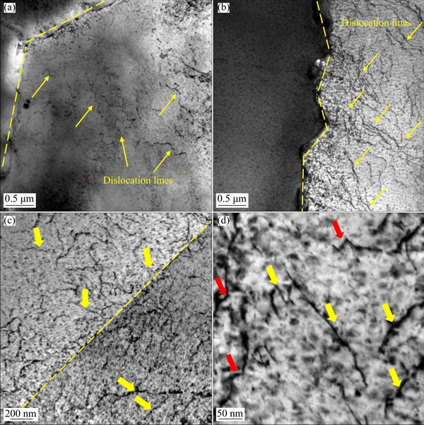
Fig. 17 TEM images of dislocation lines around grain boundaries at strains of 0.5%(a),0.6%(b) anddislocations observation at strain of 0.6% showing interaction with twin grain boundary (c)and cuttingγ′ phase(d) (Yellow arrows indicate the γ′ phases sheared by dislocations, and red arrows indicate the bending dislocations)
Table 4 Dislocation densities around grain boundaries at strains of 0.5% and 0.6% obtained through TEM calculation (ρ1) and GND analysis (ρ2)


Fig. 18 Schematic diagram of dislocation actions at strain of 0.6% (Blue ellipses indicate M23C6 carbides and orange circles indicate γ′ phases)
Masing behavior is observed when the dislocations are hindered by the second-phase particles [18]. The Masing behavior indicates that the material has a stable dislocation structure. What’s more, the cyclic softening of Ni-based superalloys, such as IN718 [47], is controlled by the gliding dislocation shearing the γ′ precipitates and planar slip. On the other hand, the cyclic hardening behavior is also associated with the formation and interaction of twins [48] and dislocation looping with γ′ precipitates [49]. Therefore, cyclic hardening is associated with dislocation accumulation and interactions with precipitates, while recrystallization nucleation and dislocation annihilation lead to cyclic softening [47].
5 Conclusions
(1) The 55Ni-23Cr-13Co nickel-based super- alloy generally exhibited initial hardening and subsequent cyclic softening behaviors when various strains were applied. The initial hardening was due to the interactions between the dislocations and the precipitates. While subsequent softening was caused by the dislocation recovery and shearing of the γ′ precipitations. The increasing fraction of substructured grains indicated dislocation recovery.
(2) The LCF life decreased as the strain increased. Coffin-Manson-Basquin and SWT relationships can well describe the fatigue life curve of the newly developed Ni-Cr-Co nickel-based superalloy.
(3) The fatigue loading effects weighed more than thermal exposure in the microstructure deformation of the studied conditions. The M23C6 precipitates showed discontinuous distribution at grain boundaries and strains of 0.5% and 0.6%, while they showed a continuous-chain distribution at a strain of 0.35%. The number of γ′ precipitates slightly increased and the size decreased with an increase in the strain which was the result of shearing of γ′ precipitates by dislocations.
(4) Cracks preferred to interrupt the twin boundaries, and cavities preferred to form around grain boundaries at higher strains. The fracture morphology of the superalloy was analyzed and the number of fatigue crack sources increased as the strain increased.
Acknowledgments
The authors are grateful for the financial supports from the National Natural Science Foundation of China (Nos. 52025052, 51975405).
References
[1] GUO Y, ZHANG Z B, ZHOU R C, HOU S F, WANG B H. Microstructure and mechanical properties of alloy 617B [J]. Transactions of Nonferrous Metals Society of China, 2015, 25(4): 1106-1113.
[2] GAO S, HOU J S, GUO Y A, ZHOU L Z. Phase precipitation behavior and tensile properties of as-cast Ni-based superalloy during heat treatment [J]. Transactions of Nonferrous Metals Society of China, 2018, 28(9): 1735-1744.
[3] HERN?NDEZ M, AMBRIZ R R, CORT?S R, G?MORA C M, JARAMILLO D. Assessment of gas tungsten arc welding thermal cycles on Inconel 718 alloy [J]. Transactions of Nonferrous Metals Society of China, 2019, 29(3): 579-587.
[4] OH JH, YOO BG, CHOI IC, SANTELLA ML, JANG JI. Influence of thermo-mechanical treatment on the precipitation strengthening behavior of Inconel 740 a Ni-based superalloy [J]. Journal of Materials Research, 2011, 26(10): 1253-1259.
[5] CHONG Y, LIU Z D, GODFREY A, LIU W, WENG Y Q. Microstructure evolution and mechanical properties of Inconel 740H during aging at 750°C [J]. Materials Science and Engineering A, 2014, 589: 153-164.
[6] MILLS WJ, JAMES LA. Effect of temperature on the fatigue propagation behaviour of Inconel X-750 [J]. Fatigue &Fracture of Engineering Materials &Structures, 2007, 3(2): 159-175.
[7] WANG K M, JING H Y, XU L Y, HAN Y D, ZHAO L, XIAO B, YANG S Q. A piecewise constitutive model, microstructure and fracture mechanism of a nickel-based superalloy 750H during high-temperature tensile deformation [J]. Journal of Materials Science, 2019, 54: 9775-9796.
[8] SRINIVASAN VS, VALSAN M, RAO KBS, MANNAN SL, RAJ B. Low cycle fatigue and creep-fatigue interaction behavior of 316L(N) stainless steel and life prediction by artificial neural network approach [J]. International Journal of Fatigue, 2003, 25(12): 1327-1338.
[9] LI H Z, JING H Y, XU L X, ZHAO L, HAN Y D, TANG Z X, XIAO B, ZHANG Y. Life, dislocation evolution, and fracture mechanism of a 41Fe-25.5Ni-23.5Cr alloy during low cycle fatigue at 700 °C [J]. International Journal of Fatigue, 2019, 119: 20-33.
[10] JING H Y, LUO Z X, XU L Y, ZHAO L, HAN Y D. Low cycle fatigue behavior and microstructure evolution of a novel 9Cr-3W-3Co tempered martensitic steel at 650?°C [J]. Materials Science and Engineering A 2018, 731: 394-402.
[11] ZHONG Z H, GU Y F, YUAN Y, YOKOKAWA T, HARADA H. On the low cycle fatigue behavior of a Ni-base superalloy containing high Co and Ti contents [J]. Materials Science and Engineering A, 2012, 552: 434-443.
[12] ZHANG P, ZHU Q, CHEN G, QIN H Y, WANG C J. Grain size based low cycle fatigue life prediction model for nickel-based superalloy [J]. Transactions of Nonferrous Metals Society of China, 2018, 28(10): 2102-2106.
[13] CHU Z K, YU JJ, SUN X F, GUAN H R, HU Z Q. High cycle fatigue behavior of a directionally solidified Ni-base superalloy DZ951 [J]. Materials Science and Engineering A, 2008, 496(1-2): 355-361.
[14] HUANG D W, YAN X J, QIN X Y, ZHANG X Y, QI M J, LIU Z W, TAO Z. Scatter in fatigue crack growth behavior of a Ni-base superalloy at high temperature[J]. International Journal of Fatigue, 2019, 118: 1-7.
[15] ZHANG M, ZHANG Y X, LIU H, ZOU Q L. Judgment criterion of the dominant factor of creep-fatigue crack growth in a nickel-based superalloy at elevated temperature[J]. International Journal of Fatigue, 2019, 118: 176-184.
[16] LIU YM, WANG L, CHEN G, LI BB, WANG XH. Investigation on ratcheting-fatigue behavior and damage mechanism of GH4169 at 650?°C [J]. Materials Science and Engineering A, 2019, 743: 314-321.
[17] DAS B, SINGH A. Understanding strain controlled low cycle fatigue response of P91 steel through experiment and cyclic plasticity modeling [J]. Fusion Engineering and Design, 2019, 138: 125-137.
[18] LI H Z, JING H Y, XU L Y, HAN Y D, ZHAO L, TANG Z X, SONG K. Microstructure mechanism, cyclic deformation behavior of an Fe-Ni-Cr alloy considering non-Masing behavior [J]. International Journal of Fatigue, 2019, 127: 537-550.
[19] NOGUCHI Y, OKADA H, HIRATA H, MINAMI F. Effect of aging on high temperature fatigue properties of Ni-23Cr-7W alloy for boiler pipes and tubes [J]. International Journal of Pressure Vessels & Piping, 2018, 165: 81-89.
[20] RAO CV, SRINIVAS NCS, SASTRY GVS, SINGH V. Low cycle fatigue, deformation and fracture behaviour of Inconel 617 alloy [J]. Materials Science and Engineering A, 2019,765: 138286.
[21] ZHANG L, ZHAO L, ROY A, SILBERSCHMIDT V, MCCOLVIN G. Low-cycle fatigue of single crystal nickel-based superalloy—Mechanical testing and TEM characterisation [J]. Materials Science and Engineering A, 2019, 744: 538-547.
[22] FAN YS, YANG XG, SHI DQ, HAN SW, LI SL. A quantitative role of rafting on low cycle fatigue behaviour of a directionally solidified Ni-based superalloy through a cross-correlated image processing method [J]. International Journal of Fatigue, 2020, 131: 105305.
[23] FU S, HSU TJ, WANG Z. Cyclic deformation behavior and related micro-mechanisms of a special CVD Ni processed with bimodal grain structures: Ultrafine (UF) grains and large grains with UF/nano twins [J]. ActaMaterialia, 2020, 182:108-119.
[24] GOPINATH K, GOGIA AK, KAMAT SV, BALAMURALIKRISHNAN R, RAMAMURTY U. Low cycle fatigue behaviour of a low interstitial Ni-base superalloy [J]. ActaMaterialia, 2009, 57(12): 3450-3459.
[25] PHILLIPS PJ, UNOCIC RR, KOVARIK L, MOURER D, WEI D, MILLS MJ. Low cycle fatigue of a Ni-based superalloy: Non-planar deformation [J]. ScriptaMaterialia, 2010, 62(10): 790-793.
[26] ZHANG P, ZHU Q, HU C, WANG CJ, CHEN G, QIN HY. Cyclic deformation behavior of a nickel-base superalloy under fatigue loading [J]. Materials Design, 2015, 69: 12-21.
[27] PLUMBRIDGE W J, DALSKI M E, CASTLE P J. High strain fatigue of a type 316 stainless steel [J]. Fatigue & Fracture of Engineering Materials & Structures, 1980, 3: 177-188.
[28] RAO KBS, SCHIFFERS H, SCHUSTER H, NICKEL H. Influence of time and temperature dependent processes on strain controlled low cycle fatigue behavior of alloy 617 [J]. Metallurgical Transactions A, 1988, 19(2): 359-371.
[29] PRAVEEN KVU, SINGH V. Effect of heat treatment on Coffin-Manson relationship in LCF of superalloy IN718 [J]. Materials Science and Engineering A, 2008, 485(1-2): 352-358.
[30] WANG M, PANG JC, LI SX, ZHANG ZF. Low-cycle fatigue properties and life prediction of Al-Si piston alloy at elevated temperature [J]. Materials Science and Engineering A, 2017, 704: 480-492.
[31] KOH SK. Fatigue damage evaluation of a high pressure tube steel using cyclic strain energy density [J]. The International Journal of Pressure Vessels and Piping, 2002, 79(12): 791-798.
[32] SARKAR A, DASH MK, NAGESHA A, DASGUPTA A, SANDHYA R, OKAZAKI M. EBSD based studies on various modes of cyclic deformation at 923?K in a type 316LN stainless steel [J]. Materials Science and Engineering A, 2018, 723: 229-237.
[33] GUGULOTH K, ROY N. Study on the creep deformation behavior and characterization of 9Cr-1Mo-V-Nb steel at elevated temperatures [J]. Materials Characterization, 2018, 146: 279-298.
[34] YE D X, PING D H, WANG Z L, XU HH, MEI X Y, XU C W, CHEN X L. Low cycle fatigue behavior of nickel-based superalloy GH4145/SQ at elevated temperature [J]. Materials Science and Engineering A, 2004, 373(1-2): 54-64.
[35] VALSAN M, PARAMESWARAN P, RAO K B S, VIJAYALAKSHMI M, MANNAN S L, SHASTRY DH. High-temperature low-cycle fatigue behavior of a nimonic PE-16 superalloy correlation with deformation and fracture [J]. Metallurgical and Materials Transactions A, 1992, 23: 1751-1761.
[36] LERCH B A, GEROLD V. Room temperature deformation mechanisms in Nimonic 80A [J]. ActaMetallurgica, 1985, 33: 1709-1716.
[37] LERCH B A, JAYARAMAN N, ANTOLOVICH S D. A study of fatigue damage mechanisms in Waspaloy from 25 to 800°C [J]. Materials Science and Engineering A, 1984, 66: 151-166.
[38] SHIN GS, YUN JY, CHUL PARK M, KIM SJ. Effect of Mo on the thermal stability of γ′ precipitate in Inconel 740 alloy [J]. Materials Characterization, 2014, 95: 180-186.
[39] WANG TT, WANG C H, GUO J T, ZHOU L Z. Stability of microstructure and mechanical properties of GH984G alloy during long-term thermal exposure [J]. Materials Science Forum, 2013, 748: 647-653.
[40] LIN J, LIU Y, DEAN T A. A review on damage mechanisms, models and calibration methods under various deformation conditions [J]. International Journal of Damage Mechanics, 2005, 14(4): 299-319.
[41] QUAN GZ, ZHANG YQ, ZHANG P, MA YY, WANG WY. Correspondence between low-energy twin boundary density and thermal-plastic deformation parameters in nickel-based superalloy [J]. Transactions of Nonferrous Metals Society of China, 2021, 31(2): 438-455.
[42] NI S, WANG YB, LIAO XZ, FIGUEIREDO RB, LI HQ, RINGER SP, LANGDON TG, ZHU YT. The effect of dislocation density on the interactions between dislocations and twin boundaries in nanocrystalline materials [J]. ActaMaterialia, 2012, 60(6-7): 3181-3189.
[43] VERMA P, SRINIVAS NCS, SINGH SR V. Low cycle fatigue behavior of modified 9Cr-1Mo steel at room temperature [J]. Materials Science and Engineering A, 2016, 652: 30-41.
[44] YADAV HK, BALLAL AR, THAWRE MM, VIJAYANAND VD. Recovery and recrystallisation during creep exposure of cold worked Ti-modified 14Cr-15Ni austenitic stainless steel [J]. Materials at High Temperatures, 2020, 37(4): 221-229.
[45] SIU KW, NGAN AHW, JONES IP. New insight on acoustoplasticity—Ultrasonic irradiation enhances subgrain formation during deformation [J]. International Journal of Plasticity, 2011, 27(5): 788-800.
[46]  J, AGHAJANI A, SOMSEN C, HARTMAIER A, EGGELER G. How dislocation substructures evolve during long-term creep of a 12% Cr tempered martensitic ferritic steel [J]. ScriptaMaterialia, 2010, 62(6): 353-356.
[47] XU J, HUANG Z, JIANG L. Effect of heat treatment on low cycle fatigue of IN718 superalloy at the elevated temperatures [J]. Materials Science and Engineering A, 2017, 690: 137-145.
[48] BEGUM S, CHEN DL, XU S, LUO AA. Low cycle fatigue properties of an extruded AZ31 magnesium alloy [J]. International Journal of Fatigue, 2009, 31(4): 726-735.
[49] STOLTZ RE, PINEAU AG. Dislocation-precipitate interaction and cyclic stress-strain behavior of a γ′ strengthened superalloy [J]. Materials Science and Engineering A, 1978, 34: 275-284.
55Ni-23Cr-13Co基合金在高温循环变形中的显微组织演变
王楷萌1,2,荆洪阳1,2,徐连勇1,2,赵雷1,2,韩永典1,2,李海舟1,2,宋恺1,2
1. 天津大学 材料科学与工程学院,天津 300350;
2. 天津市现代连接技术重点实验室,天津 300350
摘 要:通过750 °C低周疲劳试验,研究55Ni-23Cr-13Co基高温合金在应变幅度为0.35%~0.6%下的循环变形行为及显微组织演变。Coffin-Manson-Basquin和Smith-Watson-Topper模型能很好地预测该合金不同应变幅度下的疲劳寿命。在循环加载过程中,该合金表现出现循环硬化后再循环软化的特征。初始循环硬化行为是由于位错与析出物的相互作用,而循环软化行为是由位错切割γ′ 相和位错回复引起的。显微组织分析结果表明,M23C6碳化物在较低应变幅度下呈连续链状分布,而在较高的应变幅度下呈不连续分布。由于位错对γ′ 相的重复剪切作用,随着应变幅度的增大,γ′ 相的尺寸减小。分析断裂机制,在较高的应变幅度下,孔洞容易在晶界附近形成。
关键词:镍基高温合金;显微组织;低周疲劳;析出相
(Edited by Wei-ping CHEN)
1003-6326/  2021 The Nonferrous Metals Society of China. Published by Elsevier Ltd & Science Press
Abstract:The cyclic deformation behaviorand microstructure evolution of the 55Ni-23Cr-13Co nickel-based superalloy were studied at 750 °C under the strain amplitudes from 0.35% to 0.6%. Coffin-Manson-Basquin and Smith-Watson-Topper relationships were employed, which satisfactorily predicted the fatigue life of the alloy under various strain amplitudes. The superalloy showed an initial cyclic hardening as a result of the interaction between the dislocations and the precipitates, and following cyclic softening behavior mainly due to the shearing of the γ′ phase by dislocations and dislocations recovery under all strain amplitudes. Microstructure analyses showed that the M23C6 carbides exhibited a continuous-chain distribution at lower strain amplitudes, while they showed a discontinuous distribution at higher strain amplitudes. As the strain amplitude increased, the size of the γ′ phase decreased as the consequence of repeated shearing by dislocations.Fracture mechanisms were analyzed. Under higher strain amplitudes, cavities preferred to form around grain boundaries.