Trans. Nonferrous Met. Soc. China 31(2021) 3380-3393
Microstructure evolution of AA5052 joint failure process and mechanical performance after reconditioning with tubular rivet
Xiao-qiang REN1,2,3, Chao CHEN1,2,3, Xiang-kun RAN3, Yu-xiang LI3, Xin-gang ZHANG3
1. Light Alloy Research Institute, Central South University, Changsha 410083, China;
2. State Key Laboratory of High Performance Complex Manufacturing, Central South University, Changsha 410083, China;
3. School of Mechanical and Electrical Engineering, Central South University, Changsha 410083, China
Received 9July 2021; accepted 15November 2021
Abstract:
o extend the service life of the clinched joint, a reconditioning process conducted with an additional tubular rivet was proposed in this work. Different reconditioning forces were employed to produce dissimilar reconditioned joints by experimental method. The experimental results indicated that the neck fracture was the common failure mode of both original clinched and reconditioned joints. Compared with the original clinched joint, the shearing strength of the reconditioned joint produced by a reconditioning force of 40 kN increased from 1810.5 to 1986.47 N,and the energy absorption increased from 2.34 to 3.46 J. The range of effectivereconditioning force was from 35 to 40 kN and 40 kN was the best choice for reconditioning the AA5052 failed joints. The mechanical properties of the reconditioned joints are obviouslybetter than those of the original clinched joints, which fully demonstrates that the reconditioning method proposed in this work has a broad prospect of industrial application.
Key words:
mechanical reconditioning; clinched joining; tubular rivet; failure mode;
1 Introduction
Lightweight is an inevitable trend on the development of manufacturing technology in the automobile and aerospace industries.The joining technology that is compatible with it is the key technical support for the sustainable development of the above-mentioned industries [1]. The conventional joining technologies mainly include spot-welding, adhesive bonding[2], mechanical clinching [3] and friction stir welding [4]. Compared with the spot-welding technology and adhesive bonding process, the mechanical clinching process has many advantages such as no preparation requirements, environmentally, no smoke, simple operation and easy to automate [5,6]. Further, the mechanical clinching technology can be used as a solution for joining dissimilar materials, materials with oxide layers, multilayer materials and materials with different thicknesses[7-9]. The mechanical joining process is carried out by plastic deformation of the sheet material to form a mechanical interlock structure between the joined sheets [10]. The undercut generated by material flow hooks the joined sheets together to achieve the purpose of mechanical clinching. Therefore, the joint strength is an important criterion for measuring the mechanical properties of a clinched joint.
Process parameters and tooling parameters also have a direct impact on joint strength. ZHANG et al [11] prepared the clinched joints of four aluminum alloys with different die assemblies and evaluated the forming and mechanical properties of the produced joints. The die combination with the optimum quality was determined. MUCHA [12] explored the effect of clinching process parameters on the forming process and the mechanical properties of the clinched joint and investigated the stress distribution in the plastic deformation area from a microscopic perspective. HAN et al [13,14] optimized the parameters of clinching tools in the clinching process and the flat-clinching process by numerical and experimental methods. Furthermore, LAMBIASE and Di ILIO[15] performed an optimization of the clinching tools to improve the joint strength by means of integrated artificial intelligence and FE modelling and demonstrated the effectiveness of the proposed approach.
In fact, the static strength of the spot-welding and SPR joints is higher than that of the conventional clinched joints. In order to promote the application of the clinched joint, some new clinching techniques have been derived from the conventional clinching process recently. MUCHA [16] and RAN et al[17] used rectangle punch to achieve reliable joining of aluminum alloy sheets and explored the effectiveness of process parameters on the mechanical properties of clinched joints. ATIA and JAIN [18] proposed a novel die-less clinching approach by heating the clinching region for joining AA7075-T6 aluminum sheets. The application of heat softened the joined sheets and reduced the corresponding forming force as well as improved the material flow of the joined sheet. Most importantly, the shearing strength of the improved joint was increased up to 41%. To decrease the protrusion height and improve the static strength of the clinched joint, CHEN et al [19,20] investigated the mechanical properties of the reshaped joints with and without rivets by means ofexperiment and simulation methods. It was shown that the reshaping method could effectively improve the structural parameters of the mechanical interlock and thus enhance the mechanical properties of the joint.
Some scholars have tried to improve the mechanical performance of the joint by means of heat transfer and application of energy field. GRASER et al [21] applied the tailor heat treated blank (THTB) technology for the clinching process to join ductile high-strength steels (HCT780X) and aluminum alloys (AA7075). In addition, the THTB technology was demonstrated to adjust the material flow of the shear-clinching process by local and short-term heat treatment. YARCU et al [22] improved the clinching ability of an aluminum die casting alloy with a sheet metal by local annealing in order to clinch them in a process-safe manner. KACZYNSKI and SHWARSKI [23] concerned a novel method for increasing the joint strength by heating sheets from the side of the die prior to the joining process. It was proved that the innovative method increased the shearing and tensile strengths of the clinched joints by 17% and 54%, respectively. KUMAR et al [24] improved the ductility by heat-treating the base sheet in a furnace over different times and temperatures for investigating the effect of ductility on the strength of clinched joints. The results indicated that compared to the untreated material, the heat-treatment of base sheets increases the strength of clinched joints by more than 50%.
The problem of joining dissimilar materials has been an obstacle to the implementation of lightweight sheet joining in the automotive manufacturing industry. Thus, many types of studies focused on investigating the joining process of the dissimilar materials. MUCHA et al [25] realized the effective joining between AW 6082 in T6 state condition and AW 5754 in three different state conditions: H11, H22 and H24.  et al [26-28] investigated the mechanical clinching between dual-phase steel sheets and high-strength steel sheets by means of experiments and simulations. A solution is provided for the joining between metals with high hardness and low ductility. ABE et al [29] joined the high-strength steel and ultra-high-strength steel sheets by mechanical clinching method and compared the strength of the static and fatigue joints with the resistance spot welded sheets. L?DER et al [30] described the effects of moisture content on the flat-clinch joint of aluminum alloy and wood materials, which provided the possibility of joining wood and metal. JIANG et al [31,32] realized the joining of Al/steel structures and CFRP/Al structures by riveted–adhesive hybrid joining technique and electromagnetic riveting.
Besides the above-mentioned processes, many hybrid clinching technologies were emerged. These technologies make up for the shortcomings of conventional mechanical clinching to a certain extent and expand the applications of mechanical clinching technology. ZHANG et al [33] combined the resistance spot welding with mechanical clinching technologies for joining drawing-quality special-killed (DQSK) steel sheet and AA5754 aluminum alloy sheet, namely hybrid spot clinching–welding process. WANG et al [34,35] presented the laser shock clinching (LSC) for joining perforated stainless steel sheet and copper foil by experimental and numerical methods. LIN et al [36] joined alclad AA2024-T3 sheet by friction stir clinching (FSC) process, which is a simple combination of mechanical clinching with friction stir spot welding (FSSW) accurately. All of these emerging hybrid joining processes mentioned above can realize the reliable connection between the joined sheets.
In industrial applications, the joining reliability of the joint is a significant factor in evaluating the safety performance of the joint. Mechanical clinched joints will fail or crack when they are subjected to irregular loads over a long period of time. However, it is impossible to replace or re-clinch the connected components due to the limitation of working conditions. Thus, the recondition technology of the failed jointsis particularly important. In this work, a re-conditioning process implemented by the custom-built tubular rivets was proposed and investigated. The mechanical properties of the reconditioned joints were compared with those of the joints made by the conventional clinching process. The superiority of the mechanical properties of the reconditioned joint was demonstrated.
2 Linking process
2.1 Mechanism of clinched joining
The mechanical clinching process is essentially a cold extrusion deformation of the connected material under the action of the punch and die. A mechanical interlock structure is formed to achieve the purpose of joining the sheet materials together. The clinching process conducted by the fixed grooved die is presented in Fig. 1.
Before the clinching process, the joined sheets are located between the fixed grooved die and the blank holder. Then, the punch exerts preload on the upper sheet under the action of the press. With the downward movement of the punch, the sheets are partially deformed, and the material in the deformed area is pushed into the groove of the fixed die. When the lower sheet touches the groove surface of the fixed die, the material axial flow of the joined sheets is blocked. As the punch moves downward, the bottom thickness of the joint decreases and most of the materials flow axially and fill the fixed grooved dieslowly. When the loading force reaches the preset value, the punch stops pressing down and returns to the initial position. Finally, the mechanical clinching process is finished. Significantly, the absence of cracks in the joined sheets is a necessary condition for mechanical clinching [37]. Figure 2 shows the main geometric parameters of the mechanical interlock, including neck thickness (tn), undercut (ts), bottom thickness (X) and protrusion height (H). The specific roles of the main geometric parameters influence the mechanical properties of the joint directly. The protrusion height affects the application field and aesthetics of the joints in the industrial scenarios, while the relationship between the neck thickness and the undercutaffects the failure mode and static strength of the joint in the static strength test directly. As for the bottom thickness, it is a key reference for judging the mechanical forming condition without damaging the joint and indirectly reflects the relationship between the neck thickness and the undercut.
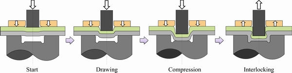
Fig. 1 Principle of mechanical clinching with fixed grooved die

Fig. 2 Geometric parameters of clinched joint
2.2 Mechanism of joint failure
It is possible that many failure modes appeared during the joint service period such as static load failure, stiffness failure and fatigue failure. In this work, the joint failure process in the static single-lap tensile shear test is illustrated. The main failure modes and joint failure process are shown in Fig. 3. It is noticed that all the failure modes of the joints produced by the fixed grooved die in this study are neck fracture.
2.3 Mechanism of mechanical reconditioning
Stable implementation of the reconditioning process is particularly important when a clinched joint fails or fractures. The reconditioned joint is required to have a similar strength to that before failure in order to meet the requirements for continued service. As depicted in Fig. 4, a pair of flat dies and a custom-built tubular rivet are used in the reconditioning process. Firstly, the tubular rivet is placed in the round hole of the upper sheet (the inner diameter of the hole is equal to the diameter of the custom-built tubular rivet). The joined sheets with the failed joint are placed between the top and bottom flat dies while on the premise of ensuring that the fracture area of the upper sheet is perfectly aligned with that of the bottom sheet. Then, the bottom flat die is fixed and the other flat die on top moves downward to compress the tubular rivet and exterior protrusion of the joint. With continuous loading, the tubular rivet is upset and plastically deformed. The upset rivet has an interference fit with the hole of the upper sheet. With the material flow of the tubular rivet, a new interlock structure is generated between the lower part of the tubular rivet and the lower sheet. Finally, the interlock structure reconnects the two layers of sheets together by the deformed rivet for the purpose of failed joints recondition.
3 Experimental
3.1 Material characterization
Recently, the AA5052 aluminum alloy has been wildly used in the automobile industry because of its excellent mechanical properties andsignificant specific strength [38]. In order to meet the industrial background of lightweight,the material used in this study is 2 mm-thickAA5052 sheets. To ensure consistency of sheet material for all experimental specimens, the AA5052 samples used for this experiment were cut into 25 mm × 80 mm (width × length) strips from a unique sheet. The AA6111 aluminum alloy was used for the custom-built tubular rivet material in this experiment. The mechanical properties ofthe experimental specimens and the custom-built tubular rivet were tested on MTS 322 physical property testing system. According to the tested results, the mechanical properties of AA5052 and AA6111 materials are depicted in Table 1. The custom-built tubular rivet and cross-sectional geometries of the rivet employed in the reconditioning process are shown in Fig. 5.

Fig. 3 Mechanism of joint failure

Fig. 4 Mechanism of mechanical reconditioning
Table 1 Mechanical properties of AA5052 and AA6111 materials

3.2 Experimental procedure
3.2.1 Mechanical clinching process
In the process of clinching AA5052 sheets, a 5.4 mm diameter punch and a fixed grooved die were used to carry out the mechanical clinching experiment, of which the geometriesare depicted in Fig. 6. The special experimental device is installed on aSust CMT-5105GJ testing machine for the clinching process. The load and displacement changes in the whole operation process are monitored and recorded at any time. In the clinching process, the punch made of SKD-11 material moved downward with a precise speed of 4 mm/min to compress the joined sheets. During the experiment, the control mode of the testing machine is force control mode to ensure that the forming load applied on all clinched joints is 40 kN. When the forming force reached 40 kN, the loading process was stopped, and the punch returned to the initial position with a preset velocity of 10 mm/min.

Fig. 5 Custom-built tubular rivets(a) and cross-sectional geometries (b) used in reconditioning process (unit: mm)
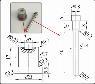
Fig. 6 Geometries of punch and fixed grooved die used in clinching process (unit: mm)
3.2.2 Failure process of clinched joint
In order to obtain the failed joint required for the reconditioning process, the clinched joint made in the previous section was destroyed to make it lose efficacy. This failure process imitated the common shearing load to perform shear failure on the clinched joint. The shearing process was also carried out on aSust CMT-5105GJ testing machine, and the displacement and force changes during the failure process were recorded. The maximum load implemented on the joint before it failed was regarded as the shearing strength of the clinched joint [39]. The failure process was carried out at a constant speed of 2 mm/min until the upper and lower sheets were completely separated. As illustrated in Fig. 7,the fracture position of the joint is the neck of the mechanical interlock, while the bottom is slightly pulled out.
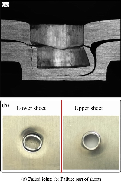
Fig. 7 Failure position of clinched joint
3.2.3 Reconditioning process of failed joint
When the clinched joint failed and new components cannot be replaced in time, the failed joint must be effectively reconditioned. Since the neck of the original mechanical interlock structure has been broken, a custom-built tubular rivet was employed to recondition the failed joint. The upsetting tubular rivet underwent the plastic deformation and a new interlock structure was generated to hook the upper and lower sheets together to achieve the purpose of reconditioning. A comparison photograph of the custom-built rivet shapes before and after reconditioning process is presented in Fig. 8.

Fig. 8 Tubular rivet shapes before and after reconditioning process
The reconditioning process was carried out onaSust CMT-5105GJ testing machine with a constant speed of 2 mm/min.In order to investigate the effect of reconditioning force on the mechanical properties of reconditioned joints, the reconditioning forces of 25, 30, 35, 40, 45 and 50 kN were selected to reconditioning the failed joints in this work. Figure 9 showsthe reconditioning evolution process with different forces in this study. The displacement of the reconditioning process shows an overall positive correlation with the reconditioning force. In the initial stage of reconditioning, the displacement increment is larger, which is the process of tubular rivets being embedded in the pits of the bottom sheet.Subsequently, the force value increases sharply. At this time, the tubular rivet is severely deformed under the action of the reconditioning forces, and the exterior protrusion height is decreased. The interaction between the sheets and the rivet causes the material to flow radially, forming a new interlock structure.

Fig. 9 Reconditioning evolution process with different forces
3.2.4 Static strength test for reconditioned joint
To evaluate the reconditioning process of the failed joints with various reconditioning forces, the static single-lap tensile shear test was conducted on dissimilar reconditioned joints, which was similar to the failure process of the clinched joint. The test speed was 2 mm/min. The highest load applied to the reconditioned joint during the test was the static strength of the reconditioned joint. In order to ensure the reliability of the experimental data, five groups of single-lap tensile shear tests were implemented for each type of reconditioned joints, and the average value of the five groups of strength data was taken as the final joint strength. Energy absorption determines how much energy the joints can withstand before failure [40,41]. Therefore, the energy absorption ability of reconditioned joints is a significant evaluation factor for the mechanical properties of the reconditioned joints.
4 Results and discussion
4.1 Material flow
To facilitate observation of the failed and reconditioned joints, Fig. 10 demonstrates the cross-sectional profiles of dissimilar reconditioned joints and failed joints. The left side of each image is the failed joint, and the right side of each image is the reconditioned joints produced by different reconditioning forces, respectively.
The increase in reconditioning force from 25 to 50 kN can be regarded as the plastic deformation of the tubular rivets and generated new mechanical interlock structures in the reconditioning process. The use of tubular rivets restores the severely deformed upper sheet material embedded in the neck of the clinching point to the origin position before failure, which provides a prerequisite for severe deformation of the tubular rivet and formation of a new interlock structure. It can be seen from Fig. 10 thatthe deformation of the tubular rivet is very small at the reconditioning forces of 25 and 30 kN. The deformation of tubular rivet increases from 35 kN reconditioning force rapidly and reaches the maximum deformation at a reconditioning force of about 40 kN. The inner wall of the tubular rivet presents a “C”-shape at the reconditioning forces of 45 and 50 kN, which is not conducive to the wrapping of the sheet material around the deformed rivet. This corresponds exactly to the relationship of reconditioned joint strength under different reconditioning forces.

Fig. 10 Cross-sectional shapes and dimensions of dissimilar failed and reconditionedjoints (unit: mm)
As the reconditioning force increases, the exterior protrusion decreases significantly. The material in the protrusion position is subjected to radial flow by the combined action of the bottom flat die and the tubular rivet, which causes the diameter of the protrusion to increase with the decrease in height. In the reconditioning process, the tubular rivet is upset first, and as the reconditioning force increases, the tubular rivet is embedded in the bottom position of the upper sheet. Subsequently, the rivet material at the lower part of the tubular rivet flows in the radial direction. The surrounding sheet material also flows radially around until the deformed rivet forms a new interlock structure to tightly hook the two layers of sheets together.
The deformation of the tubular rivet plays a vital role in the formation of the new mechanical interlock structure in the reconditioning process. The clinched joint fractured in the neck area during the failure process, which made the neck of the reconditioned joint completely inoperative when subjected to external forces. The tubular rivet was upset and plastically deformed during the reconditioning process. The upset rivet had an interference fit with the hole of the upper sheet that can be used to clasp the upper sheet. With the material flow of the tubular rivet, a new interlock structure was produced between the lower part of the rivet and the lower sheet. Then, the interlock structure reconnected the two layers of sheets together by the deformed rivet for the purpose of failed joints recondition.
4.2 Energy consumption in reconditioning process
The energy consumption represents the power dissipation of the reconditioning equipment during the reconditioning process, that is, the energy required during the reconditioning process. In order to explore the relationship between the energy consumption and optimal reconditioning force during the reconditioning process, the energy consumption in the reconditioning process was investigated. Figure 11 shows energy consumption of the failed joints reconditioned by different forces in the reconditioning process.As can be seen from Fig. 11, the energy consumption during the reconditioning process is positively correlated with the reconditioning force.
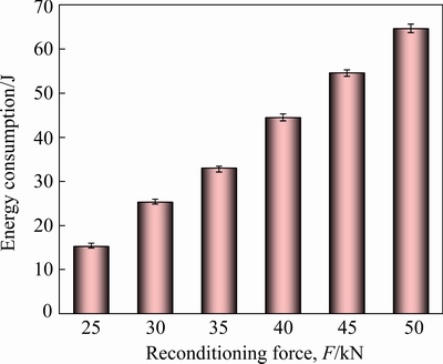
Fig. 11 Energy consumption during reconditioning process
According to the experimental results, the energy consumption of the clinched joint produced by a fixed grooved die was 94.05 J in the forming process, which was much higher than the energy consumption of the reconditioning process. In terms of energy consumption, reconditioning a damaged joint was more energy-efficient than making a new clinched joint under the premise of ensuring the mechanical properties of the joint.
4.3 Failure mode
For the clinched joints produced by the fixed grooved die, neck fracture failure mode and button separation modeare two main failure modes in the failure process [42]. If the bottom of the upper sheet is pulled out from the joint undercut on the lower sheet during the service stage, the failure mode is the button separation mode. If the thinnest area of the neck on the upper sheet is broken when overload or fatigue occurs, the failure mode is called the neck fracture failure mode [43]. In this study, the failure mode of all the clinched joints produced by the fixed grooved dieis neck fracture. Figure 12 demonstrates the fractured neck location of the failed joint in macro and micro views.

Fig. 12 Macro (a) and micro (b-d) morphologies of fracture position on failed clinched joint
Figure 12(a) shows the macroscopic profile of the fractured neck on the upper sheet. As can beseen, the macroscopic appearance of the fracture is not neat, and Area A is elongated. From the micro morphology in Area A (Fig. 12(b)), the material presents a fibrous and radial distribution, and a small number of microspores appear on the surface of this area. Further, a number of elongated dimples appear along the same direction; these characteristics indicate that this is a typical ductile fracture area. As can be seen in Fig. 12(c), a large number of short and curved tearing ridges and microspores, as well as river-shaped cracks radiating from the center of the point-shaped crack source to the surroundings, are observed in the microscopic image of Area B.Therefore, the fracture form of the material in Area B is the quasi-cleavage fracture. There are a large number of cleavage steps, elongated dimples and large microspores that are unevenly distributed in Area C(Fig. 12(d)). The cleavage steps and the tearing ridges deformed by local plastic deformation constitute the river pattern whichcanabsorb more energy before fracture. Thus, cleavage fracture is the main fracture form in Area C. In summary, the failure process of the clinched joint starts from the microspores in Area A, extends to Area B and develops into a micro-crack, and finally breaks completely in Area C.
As for the failure mode of the reconditioned joint, all the tubular rivets are pulled out from the bottom sheet along with the upper sheet shown in Fig 13. Figure 14 illustrates the fractured location of the reconditioned joint in the single-lap tensile shear test. Areas D, E and F of the reconditioned joint after the shear strength test in Fig. 14(a) correspond to Areas A, B and C of the failed clinched joint in Fig. 12(a). As can be seen in Figs. 14(b), (c) and (d), instead of elongating the dimples in all three areas, the raised tear ridgeswere flattened. The fibrous and radial distribution material disappears in Areas D, E, and F. Furthermore, the microspores and the elongated dimples become relatively flat. This is caused by the relative extrusion of the upper and lower sheets during the reconditioning process. The failure mode of the reconditioned joint indicates that the fractured neck of the reconditioned joint loses its function completely in the process of shear strength test. The reconditioning of the joint wholly depends on the insertion of the tubular rivet.

Fig. 13 Failure mode of reconditioned joint
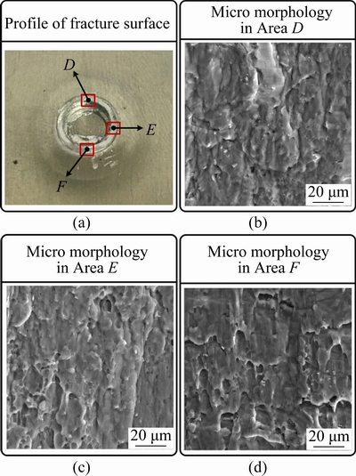
Fig. 14 Macro and micro morphologies of fracture position on failed reconditioned joint
The above analysis shows that the failure mechanisms of conventional clinched joints and reconditioned joints are completely different. When a conventional joint is subjected to shearing load, a micro-crack appears at the weakest position of the interlock neck first. As the cracks continue to expand, the neck material is torn. And as the load is applied, the interlock neck of the joint fractures. When the reconditioned joint withstands the shearing load, the outer surface of the tubular rivet and the inner wall material of the joint are extruded. With the increase of the shearing load, the rivet material and the joint material are deformed, and the rivet and upper sheet gradually slide relative to the lower plate until failure. The reconditioning process cannot change the failure mode of the joint. The failure modes of both clinched and reconditioned joints are neck fracture.
4.4 Single-lap tensile shear properties
For the reconditioning of failed joints, the most critical evaluation criterion is the comparison of the mechanical properties of the reconditioned joint with those of the clinched joint before failure. The reconditioning process has engineering significance only if the joint strength after reconditioning is greater than or equal to the strength before failure. Figure 15 shows the shearing strength–displacement curves registered in the single-lap tensile shear test on reconditioned joints with various reconditioning forces of 25, 30, 35, 40, 45 and 50 kN, respectively. All the single- lap shear force curves of the reconditioned joints produced by different reconditioning forces have the same tendency in the single-lap tensile shear test. The shearing strength of clinched joint before failure is 1810.5 N. Figure 16 depicts the average shearing strength of the reconditioned joints produced by different reconditioning forces in thesingle-lap tensile shear test.

Fig. 15 Shearing strength-displacement curves of reconditioned joints in single-lap tensile shear test at different reconditioning forces

Fig. 16 Shearing strengths of clinched and reconditioned joints in single-lap tensile shear test
As can be seen from Figs. 15 and 16, the displacement of the reconditioned joint during failure did not increase significantly in the single-lap tensile shear test. The shearing strength of the reconditioned joint was much lower than that of the clinched joint when the reconditioning force was insufficient (25 and 30 kN). However, with the increase of reconditioning force, the shearing strength of the reconditioning joint was improved significantly, reaching the maximum strength of 1986.47 N at a reconditioning force of 40 kN, which was 9.74% higher than that of the original clinched joint. When the reconditioning force increased again, the shearing strength of the reconditioned joint decreased slowly and showed a sharp decline at the reconditioning force of 50 kN.
It is worth noting that the reconditioned joint strength could not meet the requirement for industrial use when the reconditioning force was insufficient (20 and 30 kN), and its strength only reached 84.25% and 94.43% of the clinched joint strength before failure, respectively. When the reconditioning force was more than 35 kN, the shearing strength of the reconditioned joint was higher than that of the clinched joint before failure. Excessive reconditioning power not only increased energy consumption but also was not conducive to the improvement of the strength of reconditioned joints. When the reconditioning force was greater than 40 kN, the strength of the reconditioned joint began to decrease with the increase of the reconditioning force. Therefore, the selection range of reconditioning force was 35-40 kN, and the reconditioning force of 40 kN was the best choice when using this type of custom-built tubular rivet to recondition the failed joint made by a fixed grooved die.
4.5 Energy absorption
Energy absorption is another critical feature in the analysis of the mechanical properties of joint. According to the ISO 12996: 2013 standard, the energy absorption can be determined by calculating the area between the force-displacement curve and the x-axis. As shown in Fig. 17, the energy absorption is exactly described as the integral of the force-displacement curve along the direction of the failure displacement.
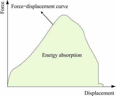
Fig. 17 Energy absorption diagram for single-lap tensile shear test
To examine the rationality of the energy absorption of the reconditioned joints, each type of five reconditioned joint failure tests were performed in this study. The energy absorption of the clinched and reconditioned joints in the single-lap tensile shear test is presented in Fig. 18.

Fig. 18 Energy absorption of clinched and reconditioned joints in single-lap tensile shear test
As can be seen in Fig. 18, the energy absorption capacity of the reconditioning joint is significantly improved after the reconditioning process compared with clinched joint. The energy absorption of the original clinched joint is 2.34 J. The energy absorption of reconditioned joint produced at 25 kN is the lowest,which is 2.65 J, while the reconditioned joint produced at40kN has the highest energy absorption value, which is 3.46 J. When the reconditioning force is less than 40 kN, the energy absorption of the reconditioned joint is positively correlated with the reconditioning force. When the reconditioning force is greater than 40 kN, the increase in reconditioning force is not conducive to the increase in energy absorption, that is, the reconditioning process consumes more energy, but absorbs less energy when the reconditioned joint fails, which is obviously not conducive to energy-saving strategy.
Overall, all of the reconditioned joints had higher energy absorption than the clinched joint before failure. Compared with the clinched joints before failure, the energy absorptions of the reconditioned joints formed by the reconditioning forces of 25, 30, 35, 40, 45 and 50 kN were increased by 12.93%, 29.24%, 30.94%, 47.76%, 27.91% and 41.02%, respectively. The energy absorption of reconditioned joints under a reconditioning force of 40 kN was the highest, which was 3.46 J. The energy absorption of reconditioned joints under a reconditioning force of25 kN was the lowest, which was 2.65 J. The experimental results prove that the reconditioned joints have more excellent mechanical properties than the initial clinched joints before failure.
This work verifies the feasibility of failed joint recondition. Although it can extend the service life of the failed joint to a certain extent, it cannot completely replace the role of the clinched joint before failure. The reconditioning process proposed in this work is suitable for temporary recondition after joint failure to ensure normal operation of the equipment and can effectively ensure production efficiency. It serves as an emergency response when the failed part cannot be replaced within a short period of time, and buys time to replace the failed part without affecting the normal use of the equipment. Regarding the research on the reconditioning process of failed joints, the next work should be focused on the investigation of the reconditioning process of failed joints of dissimilar materials and multilayer sheets. Furthermore, the investigation of the recondition mechanism is also particularly necessary.
5 Conclusions
(1) The reconditioning process can effectively repair failed joints and increase the mechanical properties of the joints to achieve the purpose of prolonging the service life of the joints. Compared with the clinched joint before failure, the reconditioned joint strength was increased by 9.74%, and the energy absorption was increased by 47.76% at a reconditioning force of 40 kN. The effective selection range of reconditioning force was 35 to 40 kN, and the reconditioning force of 40 kN was the best choice.
(2) The deformation of the tubular rivet plays a vital role in the formation of the new mechanical interlock structure in the reconditioning process. The upsetting rivet had an interference fit with the hole of the upper sheet to clasp the upper sheet. The material flow of the tubular rivet produced a new interlock structure between the lower part of the tubular rivet and the lower sheet. Eventually, the two layers of sheets were tightly rejoined together.
(3) The reconditioning process cannot change the failure mode of the joint. The failure modes of both clinched joints and reconditioned joints were neck fracture. For the failure process of the reconditioned joint, the tubular rivet was pulled out from the bottom sheet along with the upper sheet
(4) All of the single-lap shear force curves of the reconditioned joints generated by various reconditioning forces had the same tendency in the static strength test. In the reconditioning process, the exterior protrusion height of the clinched joint decreased significantly, which caused the increase of the diameter of the exterior protrusion.
Acknowledgments
Theauthorsaregratefulforthefinancialsupportsfrom the National Natural Science Foundation of China (No. 51805416), the Young Elite Scientists Sponsorship Program by CAST, China (No. YESS20200279), the Natural Science Foundation of Hunan Province, China (No. 2020JJ5716), the Project of State Key Laboratory of High Performance Complex Manufacturing, Central South University, China (No. ZZYJKT- 2019-01), the Hunan Provincial Natural Science Foundation for Excellent Young Scholars, China (No. 2021JJ20059), and the Huxiang High-Level Talent Gathering Project of Hunan Province, China (No. 2019RS1002).
References
[1] MA Yun-wu, NIU Si-zhe, SHAN He, LI Yong-bing, MA N. Impact of stack orientation on self-piercing riveted and friction self-piercing riveted aluminum alloy and magnesium alloy joints [J]. Automotive Innovation, 2020, 3(3): 242-249.
[2] LI Ying-dong, ZHAO Pi-zhi, FENG Ying-juan, CAO Hai-long. Influence of anodic oxide film structure on adhesive bonding performance of 5754 aluminum alloy [J]. Transactions of Nonferrous Metals Society of China, 2019, 29(9): 1836-1841.
[3] ABIBE A B, SONEGO M, DOS SANTOS J F, CANTO L B, AMANCIO-FILHO S T. On the feasibility of a friction-based staking joining method for polymer-metal hybrid structures [J]. Materials & Design, 2016, 92: 632-642.
[4] WANG Jian, WANG Xiao-wei, LI Bo, CHEN Cheng, LU Xiao-feng. Interface repairing for AA5083/T2 copper explosive composite plate by friction stir processing [J]. Transactions of Nonferrous Metals Society of China, 2021, 31(9): 2585-2596.
[5] CHEN Chao, LI Yu-xiang, ZHANG Hui-yang, LI Yi-bo, PAN Qing, HAN Xiao-lan. Investigation of a renovating process for failure clinched joint to join thin-walled structures [J]. Thin-Walled Structures, 2020, 151: 106686.
[6] LEI Lei, HE Xiao-cong, XING Bao-ying, ZHAO De-suo, GU Feng-shou, BALL A. Effect of foam copper interlayer on the mechanical properties and fretting wear of sandwich clinched joints [J]. Journal of Materials Processing Technology, 2019, 274: 116285.
[7] LAMBIASE F, KO D C. Two-steps clinching of aluminum and carbon fiber reinforced polymer sheets [J]. Composite Structures, 2017, 164: 180-188.
[8] ROSENTHAL S, MAA? F, KAMALIEV M, HAHN M, GIES S, TEKKAYA A E. Lightweight in automotive components by forming technology [J]. Automotive Innovation, 2020, 3(3): 195-209.
[9] CHEN Chao, ZHANG Hui-yang, XU Yong-qian, WU Jin-liang. Investigation of the flat-clinching process for joining three-layer sheets on thin-walled structures [J]. Thin-Walled Structures, 2020, 157: 107034.
[10] REN Xiao-qiang, CHEN Chao, RAN Xiang-kun, GAO Xiao-lei, GAO Yang. Investigation on lightweight performance of tubular rivet-reinforced joints for joining AA5052 sheets [J]. Journal of the Brazilian Society of Mechanical Sciences and Engineering, 2021, 43(7): 333.
[11] ZHANG Yue, XU Hong-he, PENG Rui-tao, LU Yan, ZHU Lin-wei. Joinability and mechanical properties of clinched joints of different aluminum alloys [J]. International Journal of Precision Engineering and Manufacturing, 2021, 22(11): 1883-1896.
[12] MUCHA J. The analysis of lock forming mechanism in the clinching joint [J]. Materials & Design, 2011, 32(10): 4943-4954.
[13] HAN Xiao-lan, ZHAO Sheng-dun, LIU Chen, CHEN Chao, XU Fan. Optimization of geometrical design of clinching tools in clinching process with extensible dies [J]. Proceedings of the Institution of Mechanical Engineers (Part C): Journal of Mechanical Engineering Science, 2016, 231(21): 3889-3897.
[14] HAN Xiao-lan, ZHAO Sheng-dun, CHEN Chao, LIU Chen, XU Fan. Optimization of geometrical design of clinching tools in flat-clinching [J]. Proceedings of the Institution of Mechanical Engineers (Part C): Journal of Mechanical Engineering Science, 2017, 231(21): 4012-4021.
[15] LAMBIASE F, Di ILIO A. Optimization of the clinching tools by means of integrated FE modeling and artificial intelligence techniques [J]. Procedia CIRP, 2013, 12: 163-168.
[16] MUCHA J. The analysis of rectangular clinching joint in the shearing test [J]. Maintenance and Reliability, 2011, 3: 45-50.
[17] RAN Xiang-kun, CHEN Chao, ZHANG Hui-yang, OUYANG Ya-wen. Investigation of the clinching process with rectangle punch [J]. Thin-Walled Structures, 2021, 166: 108034.
[18] ATIA M K S, JAIN M K. A novel approach to hot die-less clinching process for high strength AA7075-T6 sheets [J]. Proceedings of the Institution of Mechanical Engineers (Part C): Journal of Mechanical Engineering Science, 2020, 234(19): 3809-3825.
[19] CHEN Chao, ZHAO Sheng-dun, CUI Min-chao, HAN Xiao-lan, BEN Ning-yu. Numerical and experimental investigations of the reshaped joints with and without a rivet [J]. The International Journal of Advanced Manufacturing Technology, 2016, 88(5-8): 2039-2051.
[20] CHEN Chao, LI Yu-xiang, ZHAI Zhan-yu, ZHAO Sheng-dun, ZHANG Peng, HUANG Ming-hui, LI Y B. Comparative investigation of three different reforming processes for clinched joint to increase joining strength [J]. Journal of Manufacturing Processes, 2019, 45: 83-91.
[21] GRASER M, WIESENMAYER S, MULLER M, MERKLEIN M. Application of tailor heat treated blanks technology in a joining by forming process [J]. Journal of Materials Processing Technology, 2019, 264: 259-272.
[22] YARCU S, HUEBNER S, YILKIRAN D, BRUNOTTE K, BEHRENS B A, SCHUCHARDT T, DILGER K. Clinching of heated aluminum die casting [C]//Production at the Leading Edge of Technology.Heidelberg: Springer, 2021: 85-93.
[23] KACZYNSKI P, SKWARSKI M. Partial heating as a new method for increasing the strength of clinch joints of thin-walled elements [J]. Thin-Walled Structures, 2020, 148: 106610.
[24] KUMAR S, AVINASH G, VIMAL E. Ductility effect on clinching joint strength in lap-shear configuration loading [J]. Materials Today—Proceedings, 2021, 39: 1667-1672.
[25] MUCHA J, L, WITKOWSKI W. Research on the influence of the AW 5754 aluminum alloy state condition and sheet arrangements with AW 6082 aluminum alloy on the forming process and strength of the clinch rivet joints [J]. Materials, 2021, 14(11): 2980.
[26] L, MUCHA J,  R. Wear study of mechanical clinching dies during joining of advanced high-strength steel sheets [J]. Strength of Materials, 2017, 49(5): 726-737.
[27] L, R, MUCHA J. Finite element calculation of clinching with rigid die of three steel sheets [J]. Strength of Materials, 2017, 49(4): 488-499.
[28] L, R, MUCHA J. FEM analysis of clinching tool load in a joint of dual-phase steels [J]. Strength of Materials, 2016, 48(4): 533-539.
[29] ABE Y, SAITO T, MORI K I, KATO T. Mechanical clinching with dies for control of metal flow of ultra-high-strength steel and high-strength steel sheets [J]. Proceedings of the Institution of Mechanical Engineers (Part B): Journal of Engineering Manufacture, 2018, 232(4): 644-649.
[30] L?DER S, H?RTEL S, BINOTSCH C, AWISZUS B. Influence of the moisture content on flat-clinch connection of wood materials and aluminium [J]. Journal of Materials Processing Technology, 2014, 214(10): 2069-2074.
[31] JIANG Hao, LIAO Yu-xuan, GAO Song, LI Guang-yao, CUI Jun-jia. Comparative study on joining quality of electromagnetic driven self-piecing riveting, adhesive and hybrid joints for Al/steel structure [J]. Thin-Walled Structures, 2021, 164: 107903.
[32] JIANG Hao, ZENG Chao-chao, LI Guang-yao, CUI Jun-jia. Effect of locking mode on mechanical properties and failure behavior of CFRP/Al electromagnetic riveted joint [J]. Composite Structures, 2021, 257: 113162.
[33] ZHANG Yu, WANG Cai-mei, SHAN He, LI Yang, LUO Zhen. High-toughness joining of aluminum alloy 5754 and DQSK steel using hybrid clinching-welding process [J]. Journal of Materials Processing Technology, 2018, 259: 33-44.
[34] WANG Xiang-ying, JI Zhong, WANG Jian-feng, YOU Shu-xin, ZHENG Chao, LIU Ren. An experimental and numerical study on laser shock clinching for joining copper foil and perforated stainless steel sheet [J]. Journal of Materials Processing Technology, 2018, 258: 155-164.
[35] WANG Xiang-ying, JI Zhong, LIU Ren, ZHENG Chao. Making interlock by laser shock forming [J]. Optics and Laser Technology, 2018, 107: 331-336.
[36] LIN P C, LO S M, WU S P. Fatigue life estimations of alclad AA2024-T3 friction stir clinch joints [J]. International Journal of Fatigue, 2018, 107: 13-26.
[37] PENG Hao, CHEN Chao, ZHANG Hui-yang, RAN Xiang-kun. Recent development of improved clinching process [J]. International Journal of Advanced Manufacturing Technology, 2020, 110(11/12): 3169-3199.
[38] KHALKHALI A, MIANDOABCHI E. The application of equivalent modeling of joints for bending simulation of hybrid aluminum/high strength steel thin-walled sections joined by clinching [J]. Thin-Walled Structures, 2020, 157: 107089.
[39] PENG Hao, CHEN Chao, REN Xiao-qiang, RAN Xiang-kun, GAO Xiao-lei. Research on the material flow and joining performance of two-strokes flattening clinched joint [J]. Thin-Walled Structures, 2021, 169: 108289.
[40] HOSSEINI A, RAHMATABADI D, HASHEMI R, AKBARI H. Experimental and numerical assessment of energy absorption capacity of thin-walled Al 5083 tube produced by PTCAP process [J]. Transactions of Nonferrous Metals Society of China, 2020, 30(5): 1238-1248.
[41] LEI Lei, HE Xiao-cong, YU Tong-xin, XING Bao-ying. Failure modes of mechanical clinching in metal sheet materials [J]. Thin-Walled Structures, 2019, 144: 106281.
[42] LIU Fu-long, HE Xiao-cong, GU Feng-shou, BALL A. A comparative study of local heat treatment for enhancing overall mechanical properties of clinched joints [J]. Journal of Materials Engineering and Performance, 2021, 30(2): 1347-1355.
[43] SONG Cheng-yu, XING Bao-ying, HE Xiao-cong, WANG Shi-peng. Self-piercing riveting for single-strap butt joints in similar aluminium alloys [J]. Science and Technology of Welding and Joining, 2021, 26(4): 301-308.
AA5052接头失效过程的显微组织演变与空心铆钉修复接头的力学性能
任晓强1,2,3,陈超1,2,3,冉向坤3,李宇翔3,张新刚3
1. 中南大学 轻合金研究院,长沙 410083;
2. 中南大学 高性能复杂制造国家重点实验室,长沙 410083;
3. 中南大学 机电工程学院,长沙 410083
摘 要:为了延长无铆连接接头的使用寿命,提出一种采用空心铆钉进行修复的失效接头修复工艺。通过实验的方法,采用不同的修复力对失效无铆接头进行修复。结果表明,原始无铆接头和修复接头的失效形式一致,皆为颈部断裂失效模式。与原始无铆接头相比,当修复力为40 kN时,修复接头的抗剪载荷由1810.5 N增加到1986.47 N,能量吸收值由2.34 J增加至3.46 J。所研究的有效修复力范围为35~40 kN,对于失效AA5052无铆接头,其最优的修复力为40 kN。修复接头的力学性能明显优于原始无铆接头的力学性能,这充分说明本研究提出的无铆连接失效接头的修复工艺具有广阔的工业应用前景。
关键词:机械修复;铆接;空心铆钉;失效模式
(Edited by Wei-ping CHEN)
1003-6326/  2021 The Nonferrous Metals Society of China. Published by Elsevier Ltd & Science Press
Abstract:To extend the service life of the clinched joint, a reconditioning process conducted with an additional tubular rivet was proposed in this work. Different reconditioning forces were employed to produce dissimilar reconditioned joints by experimental method. The experimental results indicated that the neck fracture was the common failure mode of both original clinched and reconditioned joints. Compared with the original clinched joint, the shearing strength of the reconditioned joint produced by a reconditioning force of 40 kN increased from 1810.5 to 1986.47 N,and the energy absorption increased from 2.34 to 3.46 J. The range of effectivereconditioning force was from 35 to 40 kN and 40 kN was the best choice for reconditioning the AA5052 failed joints. The mechanical properties of the reconditioned joints are obviouslybetter than those of the original clinched joints, which fully demonstrates that the reconditioning method proposed in this work has a broad prospect of industrial application.