
Trans. Nonferrous Met. Soc. China 24(2014) 900-906
Solid-phase sintering process and forced convective heat transfer performance of porous-structured micro-channels
Peng-fei BAI, Zi-chuan YI, Biao TANG, Guo-fu ZHOU
South China Academy of Advanced Optoelectronics, South China Normal University, Guangzhou 510006, China
Received 2 February 2013; accepted 5 November 2013
Abstract:
A solid-phase sintering process for the low-cost fabrication of composite micro-channels was developed. Three kinds of composite micro-channels with metallic porous structures were designed. The sintering process was studied and optimized to obtain porous-structured micro-channels with high porosity. The flow resistance and heat transfer performance in the composite micro-channels were investigated. The composite micro-channels show acceptable flow resistance, significant enhancement of heat transfer and dramatic improvement of flow boiling stability, which indicates a promising prospect for the application in forced convective heat transfer.
Key words:
solid-phase sintering; composite micro-channels; porous structure; flow resistance; convective heat transfer;
1 Introduction
Forced convective heat transfer systems have shown promising prospects in applications demanding high-flux heat dissipation, such as mobile base stations, phased-array radars, laptop computers and high-power LEDs. Particularly, the flow boiling in micro-channels has attracted more and more attention because of their compact sizes, low flow resistance and effective heat transfer ability coming from the latent heat of phase change [1-4]. Though the heat transfer coefficient of near 0.5 MW/(m2��K) in micro-channels has been reported, it is far from the theoretical expectation and the heat dissipation demanding of future devices [5].
In the past few decades, numerous surface structures have been developed and applied in pool boiling enhancement [6,7]. The achievements in pool boiling heat transfer promote the studies on the enhancement of forced convective heat transfer. WANG et al [8] investigated the flow boiling heat transfer in a vertical narrow channel with sintered aluminum powder surface. The additional porous coating in the flow channel made an enhancement of 2-5 times in boiling heat transfer coefficient. WU et al [9] reported a porous coated surface with vapor channels and investigated the size and density effects of the vapor channels on boiling heat transfer. They found that the combined effects of the open channels and the porous structures significantly enhanced the heat transfer performance. KRISHNAMURTHY and PELES [10] studied the sub-cooled and low quality saturated flow boiling in a micro-channel with micro pin fins, and found the presence of pin fins considerably enhanced the heat transfer performance. As shown above, many composite micro-channels with hybrid structures have some successes in enhancing flow boiling. However, developing micro-channel which can have both high performance of heat transfer and reliable system operation is still a challenge for the application of this technology [5].
In the present study, the composite micro-channels are aimed to develop, which combine the merits of groove structures and porous coatings, for the application in convective boiling heat transfer. Three kinds of composite micro-channels with complex morphology, high surface area and excellent thermal conductivity were designed and fabricated by a low-cost solid-phase sintering process [11]. The sintering parameters were optimized. Finally, the performances of the composite micro-channels in flow resistance and flow boiling heat transfer were experimentally investigated. Due to limited space, this study mainly focuses on the design, fabrication and basic flow boiling related characterization of the composite micro-channels. The systematic investigation of the flow boiling performance in the three different kinds of porous-structured micro-channels is undertaken.
2 Design of composite micro-channels
Basically, high heat transfer performance and low flow resistance are the two main objectives for a forced convective heat transfer system. Moreover, the workability and manufacturing cost should also be considered.
Copper micro-grooves with high thermal conductivity and low flow resistance are ideal micro- channels for flow boiling. On the other hand, copper porous coating is considered to be the most viable technique for the enhancement of boiling heat transfer, which can be formed by sintering, brazing, flame spraying, forming or electro-deposition [6]. The openly connected porous structures can increase fluid disturbance, vapor/gas entrapment volume and active nucleation-site density, which significantly enhances the nucleate boiling heat transfer [12,13].
With the expectation of combining the merits of the two structures in flow boiling heat transfer, three kinds of composite micro-channels were designed. As shown in Fig. 1, by changing the geometric structure of the mold and the corresponding substrate, different micro-channels with 1 porous coating (Fig. 1(a)), 3 porous coatings (Fig. 1(b)), and porous walls (Fig. 1 (c)) can be obtained. A solid-phase sintering process [14] was employed for the formation of the porous-structured micro-channels.
3 Methodology
3.1 Fabrication of composite micro-channels
3.1.1 Materials
As shown in Fig. 2, stainless steel (06Cr19Ni10) and copper were selected as mold material and substrate material, respectively. The dramatic difference of the two materials in melting point helps to avoid the occurrence of the welding phenomenon between two metals during sintering process. The parallel micro-channels on the metal materials were fabricated by EDM wire cutting process. Because of the high specific surface area and complex morphology, dendritic copper powders (Fig. 3) made by atomization method were used for sintering porous structures. The irregular copper powders with certain diameters were selected by screening.
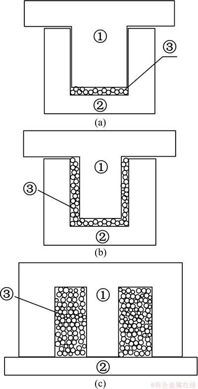
Fig. 1 Schematic diagram of structural design of composite micro-channels with 1 porous coating (a), 3 porous coatings (b) and porous walls (c)
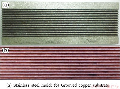
Fig. 2 Sintering module for formation of porous-structured micro-channels
3.1.2 Molding process
In order to obtain porous structures with controllable porosity and complex morphology, a die-molding technology was employed. Copper powders were uniformly filled in the chamber between the mold and the substrate by a brush coating technology. The thickness of the powder coating layers was 0.1-0.12 mm. In order to improve the dispersion effect of the copper powders, ethanol was used as dispersant. A certain pressure of 0.588 MPa was applied to the buckled sintering module by controlling the locking force.
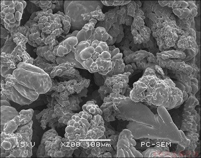
Fig. 3 SEM image of irregular dendritic copper powders
3.1.3 Sintering process
A solid-phase sintering process was employed for the formation of porous structures. The sintering temperature was controlled between 2/3-4/5 of the copper melting temperature. The effects of the sintering temperature and sintering time on the porosity of the sintered structures were studied. In the sintering experiments, the temperature elevation rate in the furnace was set at 5 ��C/min. All the sintering processes were conducted under the protection of 0.3 MPa hydrogen.
3.1.4 De-molding process
The de-molding process was controlled by de-molding temperature and the separation orientation between the mold and the sintered porous coating. A de-molding angle of more than 1�� was selected when the sintering molds were designed. The de-molding temperature employed in this study was 150 ��C.
3.1.5 Surface treatment
The burrs and impurities on copper powders may remain after the solid-phase sintering process. These structures may fall off under the impacting of thermal stress and fluid, and finally pollute the working fluid or even clog the circulation path of fluid. An electrolytic polishing process [15] was conducted after the sintering process for the treatment of sintered structures. Due to the electric field concentration effect, the corners, edges and protuberances have greater dissolution probability than that of wells, cavities and craters. As a result, the surface leveling can be achieved. The electrolyte was composed of 65% H3PO4, 15% H2SO4, 6% CrO3 and 14% deionized water (mass fraction). The counter electrode was a stainless steel sheet. The polishing process lasted for 1 min under the current density of 0.3 A/mm2.
3.2 Characterizations of sintered composite micro- channels
3.2.1 Morphology and porosity
The morphology of the sintered porous coatings was studied by scanning electron microscopy (SEM). As it is known, the fraction of porosity was associated with the degree of particle interconnectivity and particle size. Based on the equation proposed by AHMED et al [16], the porosity of each sintered porous structure was evaluated.
The apparent density of the individual specimen was calculated from the measurement of its mass and volume for each configuration. The volume of the porous structure was determined in the design of the sintering mold. Basically, the gap between the upper and lower mold halves determined the volume for the specific configuration.
3.2.2 Forced convective heat transfer performance
Sample A with bare micro-channels and three sintered composite samples B, C and D with the same structure design (Fig. 4(a)) were prepared. The porous coatings in samples B, C and D were composed of irregular copper powders with diameters of about 30, 55 and 90 ��m, respectively. The sintering process was conducted at 900 ��C for 30 min under the protection of nitrogen and hydrogen. The thickness of the porous structure was about 0.12 mm, which was controlled by a sintering mold (Fig. 1(a)). The flow resistance and flow boiling heat transfer performance in the composite micro-channels were compared with those in bare micro-channels. The experimental setup and procedure were described in details in our previous work [17]. The pressure drop in the micro-channeled samples and the temperature difference between inlet fluid and the wall of micro-channel were measured. Under the assumption of constant fluid flow, the flow resistance in the composite micro-channels was evaluated by f=(2Dh��P)/(��u2L) [18], where Dh is the hydraulic diameter of micro-channel; ��P is pressure drop; �� is the density of working fluid; u is flow rate; and L is the length of micro-channel.
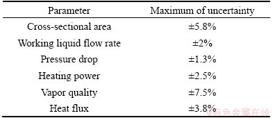
The uncertainties of applied power, temperature and pressure drop measurements were ��1 W, ��0.5 ��C and ��1 Pa, respectively. Based on the method proposed by KLINE [19], the experimental uncertainties were analyzed (Table 1).
Table 1 Uncertainties of measurements and calculated parameters
4 Results and discussion
4.1 Surface morphologies of porous-structured micro- channels
Three samples with composite micro-channels were fabricated by the solid-phase sintering route. As shown in Fig. 1, three kinds of micro-channels with 1 porous coating (Fig. 4(a)), 3 porous coatings (Fig. 4(b)) and porous walls (Fig. 4(c)) were obtained. After the de-molding process, no obvious damage was observed to the porous structure, which indicated the good metallurgical bonding between the copper substrate and the porous structure. All the sintered composite micro-channels were well shaped and shared the same hydraulic diameter of about 0.54 mm. The porous structures greatly enhanced the specific surface area of the micro-channels.
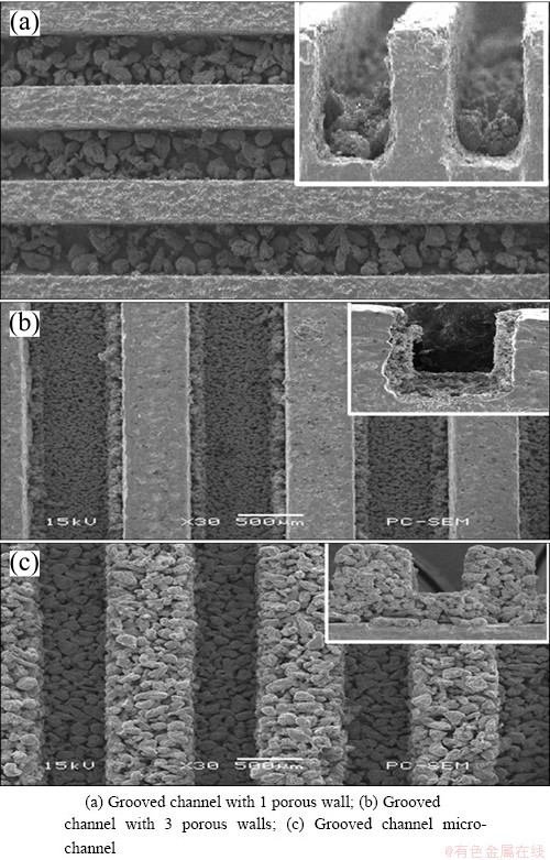
Fig. 4 SEM images of sintered samples with composite micro- channels
4.2 Optimization of sintering process
The porosity of porous structure is closely related to its thermal and penetration properties. To a boiling-enhanced surface, the porosity directly determines the volume of vapor/gas entrapment and the density of cavities which may grow into nucleate sites. Thus, porosity is a key character that should be considered during the sintering process. As shown in Fig. 5, with the increase of sintering temperature, the porosity of the sintered porous structure decreases (Fig. 5(a)). On the other hand, the effect of sintering time on the porosity is not obvious (Fig. 5(b)).
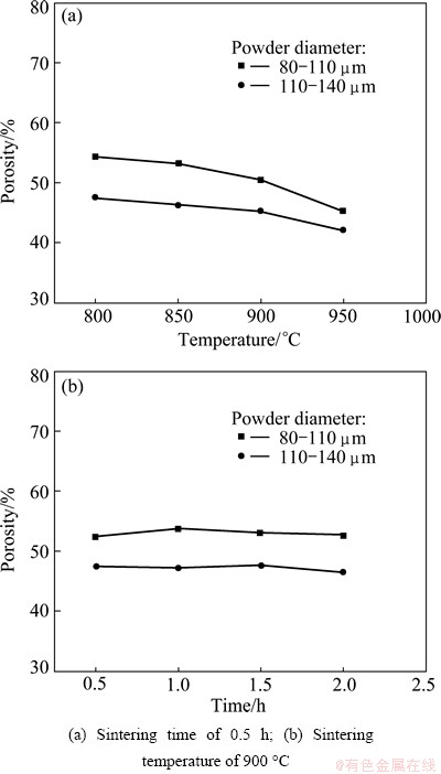
Fig. 5 Effects of sintering parameters on porosity of sintered porous coating
The decrease of porosity may be explained by the shrinkage of porous structure during the necking process [20]. The necking of copper particles is more pronounced with higher sintering temperatures and time resulting in smaller pore size and consequently smaller total porosity. Based on powder metallurgy theories, the solid-phase sintering process of copper powders is controlled by volume diffusion mechanism [21,22]. The neck growth equation can be presented as [23]
 (1)
(1)
where x is the neck radius; a is the particle radius; k is the Boltzmann constant; T is the temperature; �� is the surface tension; ��3 is the atomic volume; t is the sintering time. The coefficient of volume diffusion Dv can be given by
 (3)
(3)
where D0 is the pre-exponential factor; Qa is the heat of activation of volume diffusion. It can be found that temperature T plays an exponential role in the neck growth process while time t shows a linear influence on the process. The above equations can well explain the fact that sintering temperature is the decisive parameter in the densification process of sintering. Figure 5 also shows a dramatic reduction in porosity when the sintering temperature is beyond 900 ��C. A reduction of about 10% in porosity is recorded when the sintering temperature changs from 900 to 950 ��C.
On the other hand, a sintering process is thought to be composed of three sequential stages referred to as the initial stage, the intermediate stage, and the final stage. The initial stage of sintering generally consists of fairly rapid inter-particle neck growth by diffusion, vapor transport, plastic flow or viscous flow [24]. Any large initial differences in surface curvature can be removed in the first stage, and shrinkage accompanies neck growth as the densification mechanisms [23]. Thus, the prolonging of sintering time after the finishing of the initial sintering stage makes no obvious change in porosity. As shown in Fig. 5(b), the sintering time of 0.5 h is long enough for the metallurgical bonding of the copper powders.
In summary, to obtain a porous structure with high porosity and good metallurgical bonding, the optimal sintering temperature of 900 ��C and sintering time of 0.5 h are recommended. Under the optimal sintering condition, the porosity of about 50% and 45% (Fig. 5(a)) can be obtained for the porous coatings made from copper particles of 80-110 ��m and 110-140 ��m in diameter, respectively.
4.3 Flow resistance
As shown in Fig. 6, the samples with composite micro-channels show slightly higher flow resistances compared with the bare sample. The increase of flow resistance in the porous-structured micro-channels may be due to the increase of shear stress, which is brought about by the enhanced surface roughness and turbulence. It seems that the increase of Re intensifies the effect of porous structure on flow resistance. At low Re region, the additional flow resistance coming from porous coating may be neglected.

Fig. 6 Reynolds number Re versus flow resistance f
4.4 Heat transfer performance
The heat flux versus the temperature difference between the wall and the inlet fluid is shown in Fig. 7(a). The data are recorded at the inlet temperature of 30 ��C and flow rate of 182.8 kg/(m2��s). The superheats at phase transition points for samples B, C and D are apparently lower than that of sample A, which illustrates that the porous-coated surface facilitates the onset of flow boiling. Moreover, the porous-structured micro-channels show significant reduction of superheat compared with bare micro-channels, particularly in two-phase flow region. The enhancement of flow boiling can be due to the vapor/gas entrapped in the porous structure and the increase of nucleate sites [13,25]. Additionally, the porous-structured micro-channels show better stability than that in bare micro-channels at any vapor quality of outlet fluid (Fig. 7(b)). The improvement of flow stability may be explained by the change of bubble dynamics in porous coating layer [12,13]. The smaller diameter and higher detaching frequency of the bubbles in composite micro-channels greatly reduce the probability for the formation of vapor blanket, and finally suppress the coming of CHF [4,26].

Fig. 7 Heat flux versus temperature difference between wall (Tw) and inlet fluid (Tin) (a) and pressure drop versus vapor quality (b)
5 Conclusions
1) Three kinds of composite micro-channels which combined the merits of groove structures and porous coatings were designed.
2) A molding-sintering method was proposed for the low-cost fabrication of these porous-structured micro- channels with complex morphology and high surface area.
3) For the sake of obtaining porous structures with high porosity and good metallurgical bonding, the sintering process was investigated. The optimal sintering temperature of 900 ��C and sintering time of 0.5 h are found and recommended.
4) The flow resistance and flow boiling performance in composite micro-channels were experimentally studied. The results indicate that the introducing of porous structures brings acceptable increase of flow resistance, significant enhancement of forced convective heat transfer and dramatic improvement of stability of flow boiling compared with bare micro-channels. The composite micro-channels fabricated by solid-phase sintering show promising prospect in the application of forced convective heat transfer.
References
[1] TUCKERMAN D B, PEASE R F W. High-performance heat sinking for VLSI [J]. Electron Device Letters, IEEE, 1981, 2: 126-129.
[2] BOWERS M B, MUDAWAR I. High flux boiling in low flow rate, low pressure drop mini-channel and micro-channel heat sinks [J]. International Journal of Heat and Mass Transfer, 1994, 37: 321-332.
[3] HETSRONI G, MOSYAK A, SEGAL Z, POGREBNYAK E, Two-phase flow patterns in parallel micro-channels [J]. International Journal of Multiphase Flow, 2003, 29: 341-360.
[4] KANDLIKAR S G. Heat transfer mechanisms during flow boiling in microchannels [C]//ASME 2003 1st International conference on Microchannels and Minichannels. American Society of Mechanical Engineers, 2003: 33-46.
[5] KANDLIKAR S G. History, advances, and challenges in liquid flow and flow boiling heat transfer in microchannels: A critical review [J]. Journal of Heat Transfer, 2012, 134, 034001.
[6] WEBB R L. The evolution of enhanced surface geometries for nucleate boiling [J]. Heat Transfer Engineering, 1981, 2: 46-69.
[7] PIORO I L, ROHSENOW W, DOERFFER S S. Nucleate pool-boiling heat transfer. I: Review of parametric effects of boiling surface [J]. International Journal of Heat and Mass Transfer, 2004, 47: 5033-5044.
[8] WANG R, LI Y, GU A, HU S. The experimental study of liquid nitrogen boiling heat transfer in vertical narrow channel of porous layer surface [J]. Cryogenics, 1992, 32: 249-252.
[9] WU W, DU J H, HU X J, WANG B X. Pool boiling heat transfer and simplified one-dimensional model for prediction on coated porous surfaces with vapor channels [J]. International Journal of Heat and Mass Transfer, 2002, 45: 1117-1125.
[10] KRISHNAMURTHY S, PELES Y. Flow boiling heat transfer on micro pin fins entrenched in a microchannel [J]. Journal of Heat Transfer, 2010, 132: 041007.
[11] TANG B, TONG Y, ZHOU R, LU L S, LIU B, QU X M. Low temperature solid-phase sintering of intered metal fibrous media with high specific surface area [J]. Transactions of Nonferrous Metals Society of China, 2011, 21: 1755-1760.
[12] O'CONNOR J P, YOU S M. A painting technique to enhance pool boiling heat transfer in saturated FC-72 [J]. Journal of Heat Transfer, 1995, 117: 387-393.
[13] KIM J H, RAINEY K N, YOU S M, PAK J Y, Mechanism of nucleate boiling heat transfer enhancement from microporous surfaces in saturated FC-72 [J]. Journal of Heat Transfer, 2002, 124: 500-506.
[14] RYAN G, PANDIT A, APATSIDIS D P. Fabrication methods of porous metals for use in orthopaedic applications [J]. Biomaterials, 2006, 27: 2651-2670.
[15] BAI P F, LIU X K, YAN H, TANG B. Surface treatment of 3D outside serrated integral-fin tube manufactured by rolling and extrusion [J]. Transactions of Nonferrous Metals Society of China, 2010, 20: 844-848.
[16] AHMED Y M Z, RIAD M I, SAYED A S, AHLAM M K, SHALABI M E H. Correlation between factors controlling preparation of porous copper via sintering technique using experimental design [J]. Powder Technology, 2007, 175: 48-54.
[17] BAI P F, TANG Y, LU L S, TANG B. Investigation of flow pattern visualization and heat transfer characteristics on a Cu-base micro-channel heat sink with water coolant [J]. Journal of Jilin University: Engineering and Technology Edition, 2010, 40: 959-964.
[18] MOODY L F. Friction factors for pipe flow [J]. Transactions of the ASME, 1944, 66: 671-684.
[19] KLINE S J. The purposes of uncertainty analysis [J]. Journal of Fluids Engineering, 1985, 107: 153-160.
[20] HAUSNER H H, ROMAN O V. Linear shrinkage of metal powder compacts during sintering [J]. Soviet Powder Metallurgy and Metal Ceramics, 1965, 3: 180-184.
[21] DEDRICK J H, GERDS A. A study of the mechanism of sintering of metallic particles [J]. Journal of Applied Physics, 1949, 20: 1042-1044.
[22] ROCKLAND J G R. The determination of the mechanism of sintering [J]. Acta Metallurgica, 1967, 15: 277-286.
[23] DEMIRSKYI D, AGRAWAL D, RAGULYA A. Neck growth kinetics during microwave sintering of copper [J]. Scripta Materialia, 2010, 62: 552-555.
[24] KANG S J L. Sintering: Densification, grain growth, and microstructure [M]. Amsterdam: Elsevier, 2005.
[25] AFGAN N H, JOVIC L A, KOVALEV S A, LENYKOV V A. Boiling heat transfer from surfaces with porous layers [J]. International Journal of Heat and Mass Transfer, 1985, 28: 415-422.
[26] KANDLIKAR S G, KUAN W K, WILLISTEIN D A, BORRELLI J. Stabilization of flow boiling in microchannels using pressure drop elements and fabricated nucleation sites [J]. Journal of Heat Transfer, 2006, 128: 389-396.
���ͨ���Ĺ����ս��Ʊ����������������
�����ɣ����Ӵ����� �룬�ܹ���
����ʦ����ѧ �����Ƚ�������о�Ժ������ 510006
ժ Ҫ�����һ�ֵͳɱ������ս�������ͨ���ķ��������3�ֶ����ͨ������ͨ���Ż��սṤ�գ��Ʊ����и߿�϶�ʵĶ����ͨ�����о������ͨ�������������ʹ������ܡ���������������������ɽ��ܵķ�Χ�ڣ���������������ǿ��������������Ҳ�õ�ǿ�����������ͨ���ṹӦ���ڶ�����������������õ�ǰ����
�ؼ��ʣ������ս����ͨ������ṹ��������������������
(Edited by Chao WANG)
Foundation item: Project (51146010) supported by the National Natural Science Foundation of China; Project (S2011040003189) supported by the Doctoral Research Fund of Guangdong Natural Science Foundation, China; Project supported by the Fundation of Key Laboratory of Surface Functional Structure Manufacturing of Guangdong Higher Education Institutes, South China University of Technology
Corresponding author: Zi-chuan YI; Tel: +86-20-39314813; E-mail: yizichuan@163.com
DOI: 10.1016/S1003-6326(14)63141-1
Abstract: A solid-phase sintering process for the low-cost fabrication of composite micro-channels was developed. Three kinds of composite micro-channels with metallic porous structures were designed. The sintering process was studied and optimized to obtain porous-structured micro-channels with high porosity. The flow resistance and heat transfer performance in the composite micro-channels were investigated. The composite micro-channels show acceptable flow resistance, significant enhancement of heat transfer and dramatic improvement of flow boiling stability, which indicates a promising prospect for the application in forced convective heat transfer.
