
Trans. Nonferrous Met. Soc. China 30(2020) 1419-1428
Anodic process on Cu-Al alloy in KF-AlF3-Al2O3 melts and suspensions
Sai Krishna PADAMATA, Andrey S. YASINSKIY, Petr V. POLYAKOV
School of Non-Ferrous Metals and Materials Science, Siberian Federal University, Krasnoyarsk, Russia
Received 30 October 2019; accepted 25 March 2020
Abstract:
Anodic processes on Cu-10Al electrode in molten KF-AlF3-Al2O3 (saturated) and suspensions were characterized using chronopotentiometric and cyclic voltammetric techniques. Effects of cryolite ratio (CR= x(KF)/x(AlF3)), temperature and particle volume fraction (��) on the electrochemical behaviour of the anode were demonstrated. Initially, the anode was polarised in the galvanostatic mode in melt and suspensions (��=0.12, 0.15) at 750 ��C with 0.4 A/cm2 current density. The anode potential in melt varied between 2.5 and 3.2 V and in suspensions (��= 0.12) between 3.3 and 3.4 V. XRD analysis was conducted to study the oxide phases on the anode surface. Anode limiting current densities and mass transfer coefficients drastically decreased with the increase of �� in the suspension. The results suggest that the Cu-10Al electrode works better in suspensions with CR of 1.4 and particle volume fraction of 0.09 at 800 ��C.
Key words:
aluminium; suspension; oxidation; inert anode; cryolite melt; low-temperature electrolysis;
1 Introduction
Production of aluminium is carried out by aluminium oxide decomposition in the molten sodium cryolite at an industrial scale by using the Hall-Heroult cell. The process has been in use for more than 100 years with periodic upgrades. Carbon is used as an anode where CO2 evolution takes place, leading to the consumption of anodes on a regular basis enforcing the periodic replacement of anodes. Other than CO2, greenhouse gases like CO, COF2, CF4, and C2F6 are also emitted. The following reactions occur in the process of aluminium reduction:
Al2O3(dis)+3/2C(s) 2Al(l)+3/2CO2(g) (1)
with E0=1.168 V at 1000 ��C.
Al2O3(dis)+3C(s)2Al(l)+3CO(g) (2)
with E0=1.033 V.
4AlF3(dis)+3C(s)4Al(l)+3CF4(g) (3)
with E0=2.155 V.
2AlF3(dis)+2C(s)2Al(l)+C2F6(g) (4)
with E0=2.378 V.
This scenario can be avoided by introducing inert anode to the process, which eliminates the emission of greenhouse gases, and the cost is associated with the fabrication of the carbon anodes. Inert anodes have been the centre of interest for researchers for a while and attempts are made to find suitable materials to replace existing carbon anode. Oxygen is evolved at the inert anodes and reaction (5) takes place:
Al2O3(dis)2Al(l)+3/2O2(g) (5)
with E0=2.337 V at 750 ��C.
A material should meet the following requirements to qualify as an inert anode: (1) good electrical conductivity, (2) low corrosion rate, (3) high stability at high-temperature electrolysis, and (4) easy fabrication and low maintenance [1,2]. The energy balance and environmental challenges using inert anodes were discussed extensively earlier [3,4]. Metallic, ceramic and cermet materials were tested to date and each has its advantages and disadvantages [5-12]. Metallic anodes show promising results, as they possess high electrical conductivity and good thermal shock resistance. Moreover, the scale formed on the surface of the anode protects it from the oxidation.
During the electrolysis process, the oxide layers are formed on the surface of the metallic anode. If the oxide layer shows good conductivity and stable microstructure while adhering well with the anodic material then it can be considered as a good candidate for anodic material. However, in most cases, the oxide layers react with the cryolite, which results in corrosion. Reaction (6) would occur when the oxide scale reacts with the molten cryolite.
MxOy+2y/3Na3AlF6=MxF2y+y/3Al2O3+2yNaF (6)
The performance of an anode depends upon the electrolyte used and it is advantageous to use melts with low liquidus temperature while using metallic inert anodes to minimize the corrosion. Extensive studies have been carried out on sodium and potassium cryolites. The aluminium electrolysis process is carried out at around 960 ��C using the NaF-AlF3 melt but while using the KF-AlF3 melts, the process can be performed at 700-800 ��C. Low-temperature melts are highly desirable as inert anodes possess low corrosion rate and thermal shocks in these conditions [13-21]. Nevertheless, decreasing the electrolyte temperature leads to an increase in the decomposition voltage by 0.10- 0.15 V. Selection of Cu-Al alloy as an anode for the present study in the melts and suspensions was based on the following properties possessed by the alloy [6,22]: (1) the melting point of the anode is around 1050 ��C which allows electrolyte overheating; (2) the relatively high electrical conductivity of the alloy and its oxide scale (copper oxide and copper aluminates) formed during the electrochemical process; (3) stability of the copper aluminates in fluoride melts saturated by the oxygen ions; (4) high corrosion resistance at 750 ��C in KF-AlF3 melts with cryolite ratio CR (x(KF)/x(AlF3))=1.3-1.8.
Suspension melts have also been suggested for the aluminium electrolysis process. The particles should be evenly dispersed with no sedimentation. Zero sedimentation of alumina was obtained at a volume fraction of 0.32 [23]. This type of melt increases the purity of the produced liquid aluminium by stopping the corrosion products from contacting it and resolves the problem of maintaining the electrolyte saturated with alumina [24,25]. Although, an increase in the volume fraction of alumina results in the increased electrical resistance of the suspension. This issue can be minimized by decreasing the anode-cathode distance.
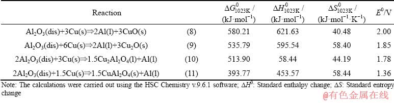
In the previous work [26,27], three anodic materials with the compositions Cu-9Al-5Fe, Cu-10Al and Cu-10Al-1.7Be were investigated at 750 ��C with KF-AlF3-Al2O3 at CR=1.3. Results suggested that Cu-10Al was performed out of the three materials at given conditions, and further research must be conducted to explore its performance at different temperatures in different melts and suspensions. Reactions shown in Table 1 occur on Cu-10Al electrode during the oxidation process and the sum of half-reactions of the oxidation-reduction which corresponds to the Gibbs energy change (��G0) and are associated with the potential difference (EMF, E0) as
E0=-��G0/(zF ) (7)
where z is the number of electrons, F=96585 C/mol is the Faraday constant.
The present study aims at determining the electrochemical behaviour of Cu-10Al anode in KF-AlF3-Al2O3 melts and suspensions. The anode was tested with melt (CR=1.3) at 750 ��C with varying particle volume fractions (��=0-0.15). Ultra-fine alumina particles were used to minimize the sedimentation. CR values and temperatures were varied in the range of 1.2-1.5 and 700-850 ��C, respectively. This article presents the results of the galvanostatic polarization and cyclic potentiometry studies performed.
Table 1 Possible reactions occurring on Cu-10Al anode at 750 ��C per 1 mol of Al
2 Experimental
2.1 Material preparation and characterisation
Alloy with a composition of Cu-10Al (wt.%) was prepared in a vacuum melting furnace at 1050 ��C. The materials used for the preparation had a purity of Cu (99.95%) and Al (99.999%). The equilibrium phase of the Cu-Al system was fcc (��Cu-Al) solid solution [28]. The specimens were cut into a cylindrical shape with dimensions of d15 mm �� 50 mm. The specimens were treated with degreasing agents (acetone and ethanol) and then dried in the air before the usage. A hole with d2.5 mm was drilled and threading was made to assemble current lead (steel rod) with the anode. The unused anodic part and the steel rods were protected with a BN tube insulator.
Electrolytes with CR between 1.2 and 1.5 were synthesized. Firstly, a crystalline form of KF was heated in the vertical furnace to remove the water present in the salt at 400 ��C for 4 h. While synthesizing the electrolyte, the AlF3 salt was placed at the bottom of the crucible and the KF salt was set at the top as AlF3 tended to sublimate quickly at 800 ��C and higher. The synthesis process was carried out for 3 h. The melt was mixed well and a portion of alumina was added corresponding to its saturation point in the melt (5 wt.%) with continuous stirring. The temperature during the preparation of melt was monitored throughout the process with the help of a K-thermocouple protected with BN sleeve, which was immersed in the electrolyte. The melt was transferred to a container where it was left to solidification. The solidified melt was then crushed and used accordingly. All the chemicals used were analytical grade and alumina used has an average particle size less than 5 ��m as shown in Fig. 1.
2.2 Cell design and experimental method
The three-electrode cell as shown in Fig. 2 was used to perform the experiments. Graphite crucible with high purity was used to contain KF-AlF3- Al2O3 (5 wt.%) melt. The crucible also acted as a counter electrode. The reference electrode Al/AlF3 was connected to the measuring device using tungsten rod. The reference electrode setup had a porous BN tube containing the liquid aluminium and KF-AlF3 electrolyte.

Fig. 1 Particle size distribution of Al2O3

Fig. 2 Experimental setup
Autolab PGSTAT302n potentiostat equipped with a 20A booster and controlled by NOVA 2.1.2 software was used to carry out the electrolysis. Electrolysis was conducted using the Chrono potentiometric method, according to which the stable potential was obtained and a relatively stable oxide layer was formed on the anodic surface. Stationary polarization was performed at current densities of 0.005-1.5 A/cm2 where the recording was made with 30 ��s of current interruption after a 120 s current passage to determine the ohmic voltage drop (IR). Cyclic voltammetry was performed at 0.05 V/s scan rate to examine the possible anodic reactions. The anodic overvoltage was calculated according to the following equation:
��a+��c=Ei-Er-IR (12)
where ��a is the activation overvoltage, ��c is the concentration overvoltage, Ei is the potential difference between the anode under current and the reference electrode, Er is the anodic reversible potential relative to the reference electrode, I is the current, and R is the resistance. The activation and concentration overvoltages were not divided, and the sum was treated as total anodic overvoltage in this work.
3 Results and discussion
3.1 Oxide layer characterisation
Initially, anodes were polarized in melts (CR=1.3) and suspensions (��=0.12) for 1-1.5 h at 750 ��C with the current density J=0.4 A/cm2 to record the change of total voltage being supposedly associated with the oxide layer formation versus time as shown in Fig. 3.
Stationary anodic polarization in melt changed between 2.5 and 3.1 V. The anodic potential was increased from 2 V (open circuit potential) up to 3.1 V. Consistent change in the anodic potential reflects the formation of different types of oxide layers (copper oxides and copper aluminates) and changes in their structures. High oscillations of the anodic potential might be associated with the formation of a new oxide layer on a consistent basis or due to the bubble evolution on the anodic surface leading to the reduction of the active surface area. No stable oxide layer was formed even after 1 h of polarization. The stable oxide layer was formed after 5000 s of polarization. In the case of anodic polarization in suspension (��=0.12), a stable oxide layer was formed from the beginning of the polarization and only a minor shift of anodic potential was observed. No fluctuations in the voltage were seen unlike anode tested in the melt. The sedimentation of alumina particles was not observed. The polarization curve of the anode in suspension (��=0.15) is not included in Fig. 3 as the anode potential with time had fluctuations and stability was not attained even after 6000 s.
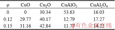
The XRD results from Fig. 4 and Table 2 show the composition of oxide layers formed on the anode during the polarization.
No CuO oxide layer was observed from XRD examination and the dominant oxide layer in terms of proportion was CuAlO2 for melts (��=0), while in suspensions (��=0.12 and 0.15) the most dominant oxide layer on the surface of the anode was Cu2O, while CuAlO2 content was low unlike in melts (��=0). No CuF or CuF2 was found on XRD patterns meaning that CuF and CuF2 produced from the process were dissolved in the electrolyte. The anodes were tested with stationary and non- stationary methods in melts (��=0) and suspensions (0.03�ܦա�0.15) at different temperatures and CR to find the best conditions at which the anode can perform.
3.2 Effect of temperature and CR
To characterize the effect of temperature and CR on the anodic behaviour of Cu-10Al alloy, both stationary and non-stationary polarization techniques were applied. Cyclic voltammetry was performed on anodes at 700 and 800 ��C in melts saturated with alumina at CR=1.2-1.5. Voltammograms recorded to observe the response of anode with the change in potential at a scan rate of 0.05 V/s are illustrated in Fig. 5.
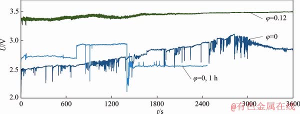
Fig. 3 Galvanostatic polarization with CR=1.3 at 750 ��C and 0.4 A/cm2
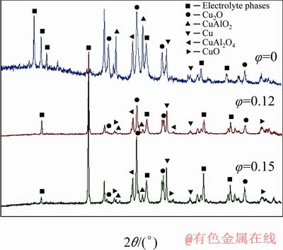
Fig. 4 XRD patterns recorded on oxide layers after anodic polarization in melts and in suspensions with ��=0.12 and 0.15 at 750 ��C
Table 2 Oxide layer composition after polarization in melt and suspension (wt.%)
Several regions can be distinguished on the curves. The ab region is between 2.1 and 2.3 V where the metal oxidation takes place. After that, the region bc with a plateau or a slight decrease in current with the potential shift toward more positive values can be observed. In Ref. [29] similar regions were indicated as the anode passivation regions. The trans-passivation process of the anode takes place in the region cd where the oxygen starts to evolve. The current density fluctuation at potentials after 2.5 V is due to the evolution of the bubble on the anode surface leading to the constant change on the active anode surface and the interpolar resistance. No passivation of the anode was observed at 800 ��C for CR=1.4 and CR=1.5. With the decrease in CR, the reduction of anodic current density at the particular anodic potentials (in oxygen region cd) can be seen.
For melts with CR=1.2 at 700 ��C, current density remains low, indicating the passivation of the anode from the beginning of the process. After an increase in the temperature to 800 ��C the shape of the curve in the oxygen region had changed. The region c��c��� appeared where the  value was higher than that of cc�� and c���d regions. The reason might be associated with the change in resistance during the sweep due to the passivation and trans-passivation phenomena. High current densities were achieved while using melts with CR=1.5. This can be related to higher alumina solubility in the melt at higher CR.
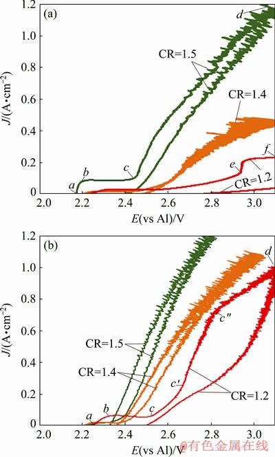
Fig. 5 Cyclic voltammograms for anode in melts with different CR (1.2-1.5) at 700 ��C (a) and 800 ��C (b)
The reversible potentials and the stationary potentials at J=0.4 A/cm2 obtained through the galvanostatic process for 1.2��CR��1.5 are illustrated in Fig. 6. An increase in CR results in the decrease of the anodic potential and evolution of oxygen at low current densities. The reason is that an increase in AlF3 concentration in the melts leads to the formation of oxyfluoroaluminates, like 

 Al4OF8 and Al4OF10 at higher rates leading to the difficulty in the ion transport between the anode and the cathode [30,31].

Fig. 6 Dependence between reversible potential (a) and stationary potential at 0.4 A/cm2 (b) in melts at 700, 750 and 800 ��C vs CR
In the case of melts with CR=1.5, the effect of temperature on the anodic potential was not observed until the oxygen evolution potential (2.34 V). The limiting current densities were observed at high potentials (3.2-4.2 V) for CR=1.2 at both the temperatures. In the case of CR=1.4, limiting currents were in the region from the potential 2.9 V. At CR=1.5, the limiting current region is between the potentials (3.4-4.2 V) in melts at 700 ��C and no limiting currents were observed at 800 ��C. In melts with CR=1.4, drastic variation in current density with respect to anodic potential was seen with the change in temperature.
According to the obtained results, the anode performed better at 800 ��C. A further increase in temperature is undesirable due to the probable decrease in corrosion resistance. The CR should be maintained at CR��1.4. The reasons for the chosen parameters are: (1) the onset potential of oxygen evolution is more negative at higher temperatures and higher CR; (2) high overvoltage is observed at temperatures below 800 ��C; (3) the stationary anodic potentials at current density 0.4 A/cm2 were similar in melts with CR=1.4 and CR=1.5; (4) in terms of the cathode process, the lower CR is preferable due to higher limiting currents of aluminium reduction [32], so the optimal CR value can be between 1.3 and 1.4.
3.3 Effect of particle volume fraction
Stationary galvanostatic polarization curves were recorded for melts (��=0) and suspension (��=0.03-0.15) under chosen conditions (T=800 ��C, CR=1.4) to estimate the limiting current density and the effect of particle volume fraction on the polarization curve. The data were compared to the previously obtained results for initially chosen conditions (T=750 ��C, CR=1.3). The plots are shown in Fig. 7 [26].

Fig. 7 Stationary galvanostatic polarization curves of anodic process in melts and suspensions (��=0-0.15) with CR=1.3 at 750 ��C and with CR=1.4 at 800 ��C (b)
The metal oxidation takes place in the region ab. The potentials in the melt (��=0) with CR=1.3 indicate the formation of copper aluminates rather than oxides (see Table 1). At point b, the potential was equal to that of the Cu/CuO electrode, which shows the formation of CuO layer on the electrode in the region bc. Point c is where the oxygen evolution starts and it can be seen that the oxygen evolution takes place at high J in the melts (��=0) and starts at low J while using suspensions. A sharp increase in the current density indicating the oxygen evolution onset can be seen in the regions fg and jk in suspension. The electrode in suspensions at ��=0.15 had no metal oxidation.
The limiting current densities were observed in the de, hi and gl regions. It is observed that the electrode used in melts (��=0) possess high limiting current density while an increase in �� drops the limiting currents, which might be due to the decrease in mass transfer coefficient ks of the oxyfluoride ions. With increasing suspension volume fraction in melts, limiting current decreases.
The comparison of the described results with those obtained in suspensions with CR 1.4 at 800 ��C allows to conclude that the limiting currents can be observed at 2.5-3 V in the suspension with ��=0.12-0.15. In the case of suspensions with lower �� (0.09) and melts, limiting current densities were not achieved up to 1 A/cm2. With an increase in the volume fraction (��) from 0.12 to 0.15, the passivation of the anode was observed. From the galvanostatic curves, it can be concluded that the volume fraction with no more than 0.09 can be used. Further increase in the �� leads to a drastic increase in overvoltage.
The cyclic voltammetry recordings were made at a scan rate of 0.05 V/s in suspensions (��=0.03-0.15) at 800 ��C and compared to those obtained previously [26] as shown in Fig. 8.
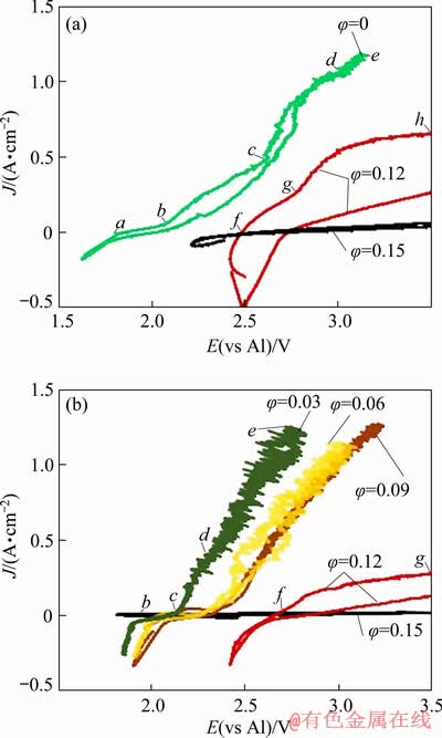
Fig. 8 Cyclic voltammograms recorded in melts and suspensions with CR=1.3 at 750 ��C (a) and with CR=1.4 at 800 ��C (b)
In the case of pure melts, low current densities were observed, reflecting metal oxidation stage in the regions ab and bc. The potential at point b was 2.07 V which is closer to the potential corresponding to Cu/CuO electrode (2.00 V). CuO might have been a dominating oxide layer on the surface of the electrode in the bc region while before that rather copper aluminate or Cu2O was formed. Oxygen evolution happened from point c where the potential of the anode was above 2.5 V in the melt with CR=1.3. It has shifted toward more negative value after an increase in CR. Point c separates the pre-oxygen and oxygen evolution regions. At the region de, an increase in the current density can be seen, which might be associated with reaction (13). In suspensions with high �� (0.12 and 0.15) at point g, the potential is more than 2.6 V, which is close to the EMF of reaction (14). The active CuO layer oxidation may take place leading to the formation of CuF2 and O2 evolution and it states the catastrophic corrosion of an oxide layer.
AlF3(l)+Cu(s) CuF2(s)+Al(l)
with E0=2.31 V. (13)
4/3AlF3(l)+2CuO(s)2CuF2(s)+4/3Al(l)+O2(g)
with E0=2.65 V. (14)
In suspensions with ��=0.12, oxygen evolution takes place from the beginning at 2.45 V and reaction (15) is expected, which occurs at potential 2.29 V. Readily formed Cu2Al2O4 oxide on the anodic surface at the beginning of the voltammetry process is transformed to CuO and oxygen evolution takes place at the same time. In the regions cd and de, the dissolution of the CuO oxide layer takes place with continuous O2 evolution at potentials close to those required for reaction (14) where CuO layer reacts with the AlF3 present in the electrolyte and CuF is expected to be the product along with Al(l) and evolution of O2.
1.5Cu2Al2O4+Al2O43CuO+5Al(l)+3O2(g)
with E0=2.29 V (15)
In the region fg, passivation of the anode may take place where the reason might be the formation of the specific oxyfluoroaluminates. In suspensions with ��=0.15, since the beginning of the sweep, high resistance was observed and no reactions occurred with considerable rate. The anode surface was completely passivated.
The dependence between the stationary current density at 2.7 V and the �� for suspension with CR=1.4 at 800 ��C is shown in Fig. 9.
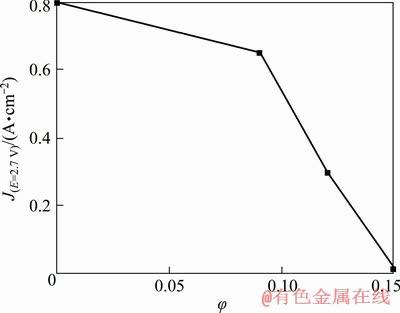
Fig. 9 Relationship between stationary current density J at anodic potential of 2.7 V (relative to Al reference electrode) and alumina particles volume fraction in suspension with CR=1.4 at 800 ��C
It can be observed that the stationary current density slightly decreases in the range of �� between 0 and 0.09. After the introduction of additional alumina particles, the limiting current density of oxygen evolution seems to be decreased. As a result, the observed stationary current density decreases rapidly with an increase in ��. Equation (16) represents the mass transfer coefficient correlated with the limiting current density and solubility of alumina [33]:
ks=Jl/(zFC) (16)
where z=2 is the number of electrons, Jl is the limiting current density, and C is the solubility. The mass transfer coefficients are calculated for the set of conditions and presented in Table 3.
Table 3 Mass transfer coefficients for diffusion of electroactive particles to anode

Clearly, ks values decrease with the increasing volume fraction in both cases; although the ks values decrease with the increase in CR. The limiting currents for CR=1.4 with �� of 0.06 and 0.09 were not observed resulting in the difficulties to estimate ks. It is worth noting that ks slightly decreases with an increase in �� if �ա�0.12. However, any further increase in �� leads to a drastic drop in ks. The obtained ks values are less compared to those obtained for gas evolving electrodes [36,37]. The low ks values are due to the smaller bubbles formed on the Cu-Al electrode compared to the ones on carbon anode [38].
4 Conclusions
(1) The dominant oxide layer on the anode surface in melts (��=0) was CuAlO2, while in suspensions (��=0.12 and 0.15) Cu2O was the dominant one.
(2) With an increase in the volume fraction of alumina, the limiting current densities of metal oxidation and oxygen evolution decrease.
(3) Passivation of the anode at the beginning of the cyclic voltammetry process was seen at 700 ��C with all CR values (1.2-1.5). The reasons might be the oxide formation or the reduction in the anodic active surface area.
(4) Particle volume fraction (��) of 0.09 is suggested for further process development.
(5) Anode possesses high oxygen evolution limiting current densities at 800 ��C.
Acknowledgments
The reported study was funded by the Russian Foundation for Basic Research, Government of Krasnoyarsk Territory, Krasnoyarsk Region Science and Technology Support Fund according to the research project No. 18-48-243014.
References
[1] GALASIU I, GALASIU R, THONSTAD J. Inert anodes for aluminium electrolysis [M]. 1st ed. Dusseldorf: Aluminium- Verlag, 2007: 207.
[2] PAWLEK R P. Inert anodes: An update [C]//GRANDFIELD J. Light Metals, TMS, 2014: 1309-1313.
[3] KVANDE H, HAUPIN W. Inert anodes for aluminium smelting: energy balances and environmental impact [J]. JOM, 2001, 53(5): 29-33.
[4] SADOWAY D R. Inert anodes for the Hall-Heroult cell: The ultimate materials challenge [J]. JOM, 2001, 53(5): 34-35.
[5] LIU Jian-yuan, LI Zhi-you, TAO Yu-qiang, ZHANG Dou, ZHOU Ke-chao. Phase evolution of 17(Cu-10Ni)- (NiFe2O4-10NiO) cermet inert anode during aluminium electrolysis [J]. Transactions of Nonferrous Metals Society of China, 2011, 21(3): 566-572.
[6] GLUCINA M, HYLAND M. Laboratory scale testing of Aluminium Bronze as an inert anode for Aluminium Electrolysis [C]//KVANDE H. Light Metals. San Francisco, CA: TMS, 2005: 523-528.
[7] NGUYEN TH, de NORA V, de NORA. Oxygen evolving inert metallic anode [C]//Light Metals. San Antonio, TX: TMS, 2006: 385-390.
[8] HELLE S, PEDRON M, ASSOULI B, DAVIS B, GUAY D, ROUE L. Structure and high temperature oxidation behaviour of Cu-Ni-Fe based alloys prepared by high-energy ball milling for application as inert anodes for aluminium electrolysis [J]. Corrosion Science, 2010, 52(10): 3348-3355.
[9] HELLE S, TRESSE M, GUAY D, ROUE L. Mechanically alloyed Cu-Ni-Fe-O based materials as oxygen evolving anodes for aluminium electrolysis [J]. Journal of Electrochemical Society, 2012, 159(4): 62-68.
[10] GAVRILOVA E, GOUPIL G, DAVIS B, GUAY D, ROUE L. Influence of Partial substitution of Cu by various elements in Cu-Ni-Fe alloys on their high temperature oxidation behaviour [C]//HYLAND M. Light Metals. Hoboken: TMS, 2015: 1187-1191.
[11] ZAIKOV Y P. Ceramic properties of electrodes based on NiO-Li2O and their solubility in cryolite alumina melts [C]//8th Al Symposium. Slovakia, Ziar nad Hronom- Donovaly, 1995: 239-241.
[12] HAARBERG G M. The interaction between tin oxide and cryolite-alumina melts [C]//9th International Symposium on Molten Salts. San Francisco, USA: Electrochemical Society, Inc., 1994: 568-577.
[13] NGUYEN Q M. Extraction of metals by molten salt electrolysis: Chemical fundamentals and design factors [J]. JOM, 1985, 37: 28-33.
[14] GRJOTHEIM K, MALINOVSKY M, MATIASOVSKY K. The effect of different additives on the conductivity of cryolite-alumina melts [J]. JOM, 1969, 21: 29-33.
[15] SOLHEIM A, ROLSETH S, SKYBAKMOEN E, STOEN L. Liquidus temperature and alumina solubility in the system Na3AlF6-AIF3-LiF-CaF2-MgF2 [C]//BEARNE G, DUPUIS M, TARCY G. Light Metals. Warrendale: TMS, 1995: 73-82.
[16] WANG J, LI C, CHAI D, ZHOU Y, FANG B, LI Q. Relationship between aluminium electrolysis current efficiency and operating condition in electrolyte containing high concentration of Li and K [C]//MARTIN O. Light Metals. TMS, 2018: 621-626.
[17] DEDYUKHIN A, APISAROV A, TIN��GHAEV P, REDKIN A, ZAIKOV Y. Electrical conductivity of the KF-NaF-AlF3 molten system at low cryolite ratio with CaF2 addition [C]//LINDSAY S J. Light Metals. Hoboken: TMS, 2011: 563-565.
[18] DEWING E W. Loss of current efficiency in aluminium electrolysis cell [J]. Metallurgical Transaction B, 1991, 22: 177-182.
[19] KORENKO M, PRISCAK J, SIMKO F. Electrical conductivity of system based on Na3AlF6-SiO2 melt [J]. Chemical Papers, 2013, 67: 1350-1354.
[20] KORENKO M, VASKOVA Z, SIMKO F, SIMURDA M, AMBROVA M, SHI Z. Electrical conductivity and viscosity of cryolite electrolytes for solar grade silicon (Si-SoG) electrowinning [J]. Transactions of Nonferrous Metals Society of China, 2014, 24: 3944-3948.
[21] PADAMATA S K, YASINSKIY A S, POLYAKOV P V. Electrolytes and its additives used in aluminium reduction cell: A review [J]. Metallurgical Research and Technology, 2019, 116: 410.
[22] TKACHEVA O, SPANGENBERGER J, DAVIS B, HRYN J. Aluminium electrolysis in an inert anode cell [C]//Molten Salts Chemistry and Technology. USA: John Wiley & Sons, Ltd, 2014: 53-69.
[23] YASINSKIY A S, POLYAKOV P V, VOYSHEL Y V, GILMANSHINA T R, PADAMATA S K. Sedimentation behaviour of high-temperature concentrated colloidal suspension based on potassium cryolite [J]. Journal of Dispersion Science and Technology, 2018, 39: 1492-1501.
[24] YASINSKIY A, SUZDALTSEV A, PADAMATA S K, POLYAKOV P, ZAIKOV Y. Electrolysis of low�C temperature suspensions: An update [C]//TOMSETT A. Light Metals. Cham: TMS, 2020: 626-636.
[25] KELLER R, ROLSETH S, THONSTAD J. Mass transport considerations for the development of oxygen-evolving anodes in aluminium electrolysis [J]. Electrochimica Acta, 1997, 42: 1809-1817.
[26] YASINSKIY A S, PADAMATA S K, POLYAKOV P V, VINOGRADOV O O. Anodic process on aluminium bronze in low-temperature cryolite-alumina melts and suspensions [J]. Tsvetnye Metally, 2019, 9: 42-49. (in Russian)
[27] YASINSKIY A S, PADAMATA S K, POLYAKOV P V, SAMOILO A S, SUZDALTSEV A V, NIKOLAEV A Y. Electrochemical behaviour of Cu-Al oxygen-evolving anodes in low-temperature fluoride melts and suspensions [C]//TOMSETT A. Light Metals. Cham: TMS, 2020: 591-599.
[28] GOHAR G A, MANZOOR T, SHAH A N. Investigation of thermal and mechanical properties of Cu-Al alloys with silver addition prepared by powder metallurgy [J]. Journal of Alloys and Compounds, 2018, 735: 802-812.
[29] CAO D, SHI Z, SHI D, XU J, HU X, WANG Z. Electrochemical oxidation of Fe-Ni alloys in cryolite- alumina molten salts at high temperature [J]. Journal of Electrochemical Society, 2019, 166(4): E87-E96.
[30] RATKJE S K. Oxy-fluoro aluminate complexes in molten cryolite melts [J]. Electrochimica Acta, 1976, 21: 515-517.
[31] PICARD G S, BOUYER F C, LEROY M, BERTAUD Y, BOUVET S. Structures of oxyfluoroaluminates in molten cryolite-alumina mixtures investigated by DFT-based calculations [J]. Journal of Molecular Structure: THEOCHEM, 1996, 368: 67-80.
[32] NIKOLAEV A Y, SUZDALTSEV A V, POLYAKOV P V, ZAIKOV Y P. Cathode process at the electrolysis of KF-AlF3-Al2O3 melts and suspensions [J]. Journal of Electrochemical Society, 2017, 164(8): H5315-H5321.
[33] CANIZARES P, GARCIA-GOMEZ J, FERNANDEZ DE MARCOS I, RODRIGO M A, LOBATO J. Measurement of mass-transfer coefficients by an electrochemical technique [J]. Journal of Chemical Education, 2006, 83: 1204-1207.
[34] YAN H, YANG J, LI W, CHEN S. Alumina solubility in KF-NaF-AlF3-Based low-temperature electrolyte [J]. Metallurgical and Materials Transactions B, 2011, 42: 1065-1070.
[35] TKACHEVA O, ZAIKOV Y, APISAROV A, DEDYUKHIN A, REDKIN A. The aluminum oxide solubility in the KF-NaF-AlF3 melts [C]//Proceedings of the Eight Israeli-Russian Bi-national Workshop. Israel: Israel Academy of Science and Humanities, 2009: 175-182.
[36] WEYAND J D, DEYOUNG D H, RAY S P, TARCY G P, BAKER F W. Inert anodes for aluminium smelting. Contract DE-FC07-80CS40158, Final Report, DOE/CS/40158-20, 1986.
[37] STRACHAN D M, KOSKI O H, MORGAN L G, WESTERMAN R E, PETERSON R D, RICHARDS N E, TABEREAUX A T. Results from a 100-hour test of a cermet anode: Materials aspects [C]//Light Metals. Anaheim, CA: TMS, 1990: 395-401.
[38] BURNAKIN V. Fluid dynamics in electrometallurgy of aluminium and magnesium [D]. Krasnoyarsk, 1990: 330. (in Russian).
KF-AlF3-Al2O3���������Һ��Cu-Al�Ͻ����������
Sai Krishna PADAMATA, Andrey S. YASINSKIY, Petr V. POLYAKOV
School of Non-Ferrous Metals and Materials Science, Siberian Federal University, Krasnoyarsk, Russia
ժ Ҫ��ʹ�ü�ʱ��λ��ѭ������������������KF-AlF3-Al2O3(����)������Һ��Cu-10Al�缫�������̣�֤������ʯ��(CR=x(KF)/x(AlF3))���¶ȺͿ����������(��)�������绯ѧ��Ϊ��Ӱ�졣�������750 ��C�͵����ܶ�Ϊ0.4 A/cm2�������£��Ժ����ģʽ�����������Һ(��=0.12��0.15)�н������������������е�����������2.5~3.2 V֮��仯������Һ(��=0.12)��������������3.3~3.4 V֮��仯������XRD��������������������ࡣ�����������ܶȺʹ���ϵ������������Һ��������������Ӷ������½����о����������ʹ��Cu-10Al�����ĽϺù��ղ����ǣ�800 ��C������CR 1.4�������������Լ0.09��
�ؼ��ʣ���������Һ����������������������ʯ���壻���µ��
(Edited by Xiang-qun LI)
Corresponding author: Sai Krishna PADAMATA; E-mail: saikrishnapadamata17@gmail.com
DOI: 10.1016/S1003-6326(20)65307-9
Abstract: Anodic processes on Cu-10Al electrode in molten KF-AlF3-Al2O3 (saturated) and suspensions were characterized using chronopotentiometric and cyclic voltammetric techniques. Effects of cryolite ratio (CR= x(KF)/x(AlF3)), temperature and particle volume fraction (��) on the electrochemical behaviour of the anode were demonstrated. Initially, the anode was polarised in the galvanostatic mode in melt and suspensions (��=0.12, 0.15) at 750 ��C with 0.4 A/cm2 current density. The anode potential in melt varied between 2.5 and 3.2 V and in suspensions (��= 0.12) between 3.3 and 3.4 V. XRD analysis was conducted to study the oxide phases on the anode surface. Anode limiting current densities and mass transfer coefficients drastically decreased with the increase of �� in the suspension. The results suggest that the Cu-10Al electrode works better in suspensions with CR of 1.4 and particle volume fraction of 0.09 at 800 ��C.
