
J. Cent. South Univ. (2016) 23: 1416-1426
DOI: 10.1007/s11771-016-3194-x

Design and optimization in multiphase homing trajectory of parafoil system
GAO Hai-tao(�ߺ���)1, 2, TAO Jin(�ս�)2, SUN Qing-lin(������)2, CHEN Zeng-qiang(����ǿ)2
1. Department of Physics and Electronics, Anhui Science and Technology University, Fengyang 233100, China;
2. College of Computer and Control Engineering, Nankai University, Tianjin 300071, China
 Central South University Press and Springer-Verlag Berlin Heidelberg 2016
Abstract:
In order to realize safe and accurate homing of parafoil system, a multiphase homing trajectory planning scheme is proposed according to the maneuverability and basic flight characteristics of the vehicle. In this scenario, on the basis of geometric relationship of each phase trajectory, the problem of trajectory planning is transformed to parameter optimizing, and then auxiliary population-based quantum differential evolution algorithm (AP-QDEA) is applied as a tool to optimize the objective function, and the design parameters of the whole homing trajectory are obtained. The proposed AP-QDEA combines the strengths of differential evolution algorithm (DEA) and quantum evolution algorithm (QEA), and the notion of auxiliary population is introduced into the proposed algorithm to improve the searching precision and speed. The simulation results show that the proposed AP-QDEA is proven its superior in both effectiveness and efficiency by solving a set of benchmark problems, and the multiphase homing scheme can fulfill the requirement of fixed-points and upwind landing in the process of homing which is simple in control and facile in practice as well.
Key words:
1 Introduction
Parafoil system is a very unique class of flexible vehicle, which is composed of a traditional ram-air umbrella, loads and GNC (guidance navigation & control) equipment, of which flight characteristics are: gliding without manipulation, turning though pulling the left or right steering line on both sides of the trailing edge, and flare landing through pulling the two steering lines symmetrically. The slow flight and large payload characteristic of parafoil system make it a practical platform for application such as UVA (unmanned aerial vehicle), CRV (crew return vehicle) and GPADS (guided parafoils air drop system) [1-3].
In recent years, with the development of large size ram-air parafoil, global position system (GPS), miniaturized powerful sensor and micro control units (MCUs), the implementation of fully autonomous homing becomes feasible. Homing trajectory planning and optimization is overwhelmingly crucial to realize autonomous precision homing, and the pros and cons of homing trajectory affect the effect of homing to a great extent. At present, a variety of homing trajectory planning methods have been recommended, that are the blind-angled planning method, the optimal planning method and the multiphase planning method [4]. The blind-angled planning method is easy to realize, but the control quality is poor. The optimal planning method is on the basis of optimal control theory, and the optimal control law and homing trajectory that satisfy various restraining conditions are obtained by calculation. The control quantity of parafoil optimal control is changed continuously, indicating that in the homing process, the control on the left and right motors are frequent, leading to the complexity of the homing control [5-7]. The multiphase homing divides the whole trajectory into several phases, which is simple in control and facile in practice as well [8-11].
This work focuses on the study of multiphase homing trajectory designing of parafoil systems. Additionally, auxiliary population-based quantum differential evolution algorithm (AP-QDEA) is applied as a tool to optimize the trajectory. The proposed algorithm combines the strengths of differential evolution algorithm [12-13] and quantum evolution algorithm [14-16], involves the quantum bit coding and quantum gate updating of QEA, and inherits ideas of crossover, mutation and competition from DEA. In addition, the notion of auxiliary population is introduced into the proposed algorithm to improve the searching precision and speed, as well as avoid falling into local optimum. Through the simulation, the power of AP-QDEA has been revealed and the homing trajectory planning scheme is proved to be feasible for autonomous homing of parafoil system.
2 Mathematic model of parafoil system
The dynamic model of parafoil system is highly complex and nonlinear, and always has strong coupling. Therefore, the particle model is typically used in place of the complex and high degree of freedom model in homing trajectory planning. This way can greatly simplify calculations in process.
2.1 Wind coordinate system
The wind coordinate system is often adopted in homing trajectory design of parafoil system. The direction of each coordinate axis in the wind coordinate system is consistent with the geodetic coordinate system. Its original point moves with the airflow. The origin of wind coordinate system is coincided with the origin of geodetic coordinate system at the time when flare landing is implemented. Thus, the degree and direction of wind can be transformed into the shift position of the original point. At any time t, t0 �� t �� tf, the distance between the origin of the two coordinate systems can be expressed as
 (1)
(1)
where Oe is the origin of the geodetic coordinate system, Of is the origin of the wind coordinate system, and vwind is the speed of wind.
2.2 Establishment of particle model
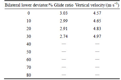
The flight control of parafoil system is realized by manipulations of left or right control ropes on its trailing edge. In Ref. [17] a six-degree freedom movement equation of parafoil system is established. Simulation results of the six degrees of freedom model is shown in Tables 1-2.
It can be seen from Table 1 that bilateral lower deviator has little effect on gliding performance of parafoil system except for flare landing. Therefore, unilateral lower deviator is only considered for control. As given in Table 2, the increase of unilateral lower deviator leads to the decrease of gliding ratio and roll angle. Consequently, the unilateral lower deviator is usually limited within a certain range for it will damage holistic stability when being reduced to a certain degree (since the unilateral lower deviator reaches 40%, the parafoil system is in stall condition). Accordingly, in order to simplify the model, the following assumptions are established:
1) The horizontal and vertical velocities remain unchanged by ignoring effects caused by the variation of atmospheric density.
2) The horizontal wind field is fixed and known.
3) The control response of parafoil system is without any delay.
Based on the above assumptions and wind coordinate system, the coordinate origin is selected where flare landing begins to implement. The motion equation of parafoil system can be simplified as
 (2)
(2)
where (x, y, z) denotes the location information of parafoil system, vs denotes its horizontal velocity, vz denotes its vertical velocity, �� denotes its heading angle, �� denotes its yaw rate, u denotes the control quantity with the scope of [-umax, umax], and there exists a one-to-one relationship between u and the unilateral lower deviator, which is closely related to the turning radius of parafoil system R. The relation is known as u=vs/R.
Table 1 Glide ratio with increase of bilateral lower deviator
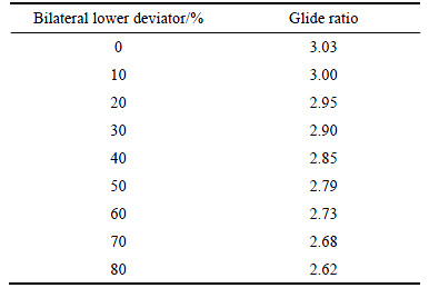
Table 2 Glide ratio with increase of unilateral lower deviator
3 Design of multiphase homing trajectory
As we all know, stable gliding belongs to the vertical plane movement whose projection is a line segment in the horizontal plane, while, turning is downward spiral movement whose projection is a circular arc. In this case, homing trajectory in horizontal plane is selecting the appropriate combination of arc and line segment. Under the guidance of the above concept, no matter how different the specific segmentation is, the multiphase homing trajectory can be generally divided into three different stages artificially which includes:
1) Centripetal phase: in this section, a target acquisition turn is often made at the starting time such that the subsequent homing trajectory is heading towards the target point.
2) Energy management phase: this section always takes up a lot of time, among which the vehicle hovers on the landing area until the height meets certain requirements.
3) The last phase is called landing phase where the direction of flight is prepared for the implementation of flare landing, and the whole procedure usually takes the following three steps when flying against the wind, gliding, and flare landing.
The homing schematic of parafoil system is shown in Fig. 1.
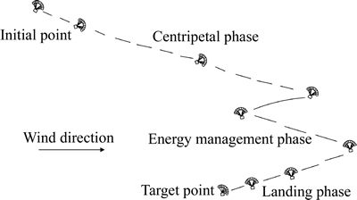
Fig. 1 Homing schematic of parafoil system
3.1 Multiphase strategy
In this work, a classical multiphase homing trajectory planning scheme successfully verified in the X-38 flight experiment [18] is adopted on the basis of energy saving, landing precision, flight safety and its exploitativeness. The multiphase strategy in horizontal plane is illustrated in Fig. 2.
As shown in Fig. 2, A denotes the initial point of parafoil system, G denotes the target point, D denotes the entry point of the energy management circle with radius Rep, and ��ep denotes the angle of 
 denotes the centripetal phases, where the parafoil system is gliding towards the target point.
  denotes the energy control phase, where the parafoil system is turning to consume the extra potential energy.
  denotes the landing phase.
  ,
,  and
and  denote the transition phases, where the parafoil system is turning with the minimum turning radius. ��i (i=1, ��, 4) denotes the corresponding central angle of each turning phase. The characteristic of the multiphase homing trajectory is that: a target acquisition turn
  is made to fly heading towards the energy management area. A descent entry turn is made to enter the energy management circle. Finally, an energy management circle exit turn is performed such that the landing point is approaching opposite to the wind direction.
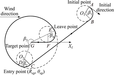
Fig. 2 Multiphase strategy in horizontal plane
This may need further explanations once the height of initial point is insufficient, which, in another word, means the horizontal distance from the initial point to target point is greater than the product of initial height and glide ratio. The initial point belongs to regions [4] where the parafoil system is unable to realize accurate fix-point homing due to the fact that the initial height is too low to guarantee enough flight time. Considering that the air dropping spot of parafoil system is always carefully calculated and selected, the kind of situation is not a subject to be discussed in this work.
3.2 Establishment of optimization objective
According to the geometric relationship of each phase trajectory, the key step in the multiphase homing trajectory planning is to determine the location of the entry point D with Rep and ��ep. When D is determined, the whole trajectory will be fixed.
In the process of homing, the landing precision and energy consumption should be considered. Therefore, unilateral control method is adopted and the minimum turning radius is used for adjusting flight direction, which means that the parafoil system flies along the circular arc , and with the minimum turning radius Rmin, and the scope of central arc ��1, ��2 and ��4 is [0, ��]. The rest is to find a suitable entry point D, so as to make the whole trajectory optimal. To ensure the deviation between the landing point and the target point minimum, the optimized objective function J is the absolute value of the deviation between the horizontal distance and the corresponding horizontal distance of the initial height under the condition of the constant glide ratio. Thus J is established as
 (3)
(3)
where Rmin��(��1+��2+��4) denotes the total length of arc , and , Rep����3 denotes the length of arc  ,
,  denotes length of line
 denotes the length of line
  f��z0 denotes the horizontal flight distance corresponding to the initial height of parafoil system. The variables of the multi- phase trajectory parameters are Rep and ��ep, thus the trajectory planning problem is transformed into the parameters optimization problem.
3.3 Calculation of multiphase trajectory
(x0, y0, z0) denotes the initial position of parafoil system, and dt denotes its turning direction. If the vehicle turns in clockwise, then dt=-1, otherwise, dt=1. ��0 denotes its initial flight direction.  denotes the vector from central point O1 to central point O2, which has the same length and direction with
 is the angle of
  which is calculated as

 (4)
(4)
The transition arc angle ��i (i=1, 2, 4) are calculated as
 (5)
(5)
where and ��i (i=1, 2, 3) are calculated as
 (6)
(6)
 (7)
(7)
The transition arc angle ��3 is calculated as
 (8)
(8)
where n is a natural number, which denotes the extra circle number of energy control phase that can be calculated by Eq. (9).
 (9)
(9)
where the symbol �� �� denotes taking the lower limit value.
��1, ��2 and ��3 can only be positive, which are processed as
 (10)
(10)
In order to save control energy and improve the flight stability of parafoil system, the scope of Rep and ��ep can be limited as
 (11)
(11)
where R2 and R1 are the upper and lower limits of energy management circle.
4 Optimization algorithm
For the objective function J, shown as Eq. (3), the number of optimized parameters is few. Therefore, the optimization algorithm has less requirement for running time but better search ability, search accuracy and higher robustness. In this case, AP-QDEA is proposed by combining the crossover mutation of DEA with coding and quantum gate updating of QEA. In AP-QDEA, several individuals are randomly selected for complementary mutation to implement local searching so as to strengthen local searching capability and enhance searching efficiency and precision. The notion of auxiliary population is introduced to diversify the population. In order to prove its effectiveness, the proposed algorithm was compared with DEA by testing on a set of benchmark functions and evaluating on several performance evaluation indexes.
4.1 Algorithm strategy
4.1.1 Individual coding and population initialization
The real number-probability amplitude coding scheme is adopted in AP-QDEA, by which the characteristics of real number coding of DEA and probability amplitude coding of QEA are inherited. The individual  is coded as
 (12)
(12)
where i denotes the i-th individual of the population, N denotes the population size, D denotes the dimension of individuals, g denotes the evolution generations. Each component of individual consists of x, �� and ��. �� and �� are the probability amplitudes of x, which satisfy the normalized condition of Eq.(13).
 ,
,  (13)
(13)
xi,j in  is initialized by
 ,
, (14)
(14)
where rj denotes a random number in [0, 1]. The initializations of ��i,j and ��i,j are given as
 (15)
(15)
where ��i,j=2����ri,j, and ri,j denotes a random number in [0, 1].
4.1.2 Complementary mutation
The population is first operated by the complementary mutation. Several individuals are chosen randomly, and each component of the single individual is mutated. Gaussian mutation to the j-th component of the individual
  is given as
 , (16)
where denotes a Gaussian distributed random number, whose mean value is 0 and variance is
  (k=��, ��). The value of is taken as
 (17)
(17)
When the component value of new individuals is beyond the range, the operation of Eq. (18) is implemented (repetitive operation) to make it back to within the range.
 (18)
(18)
If the mutated individuals are better than before, the mutation is effective, and vice versa.
4.1.3 Differential evolution
The differential evolution of AP-QDEA adopts the evolution method of main population and auxiliary population simultaneously. Individuals of main population for differential evolution are the ones after complementary mutation, while individuals of auxiliary population consist of intrinsic individuals with high quality and individuals with relatively high quality which are generated in evolution process of the main population. The differential evolution of auxiliary population is described as follows.
1) Population initialization
The initial auxiliary population is generated according to Eq. (19). wi denotes individual in auxiliary population, wi,j denotes the j-th component of the i-th individual, and the population size N is chosen according to actual conditions. In this work, the population size of auxiliary population is the same as the main population.
 (19)
(19)
2) Mutation operation
The mutation operation is carried out to all individuals of auxiliary population. Three different individuals 
 and
and  are chosen randomly in auxiliary population, and the i-th individual
 (i=1, 2, ��, N) is mutated as
 ,
,  (20)
(20)
where F denotes the scaling factor, whose value range is limited in [0, 2], and  denotes the new individual after mutation.
3) Crossover operation
Let be the new individual generated by crossover operation, shown as
 (21)
(21)
The crossover operation of Eq. (22) is carried out to each individual  (i=1, 2, ��, N):
 (22)
(22)
where r denotes a random number in [0, 1], C�� denotes the crossover factor in [0, 1], j denotes the j-th component of the i-th individual, j=1, 2, ��, D, and j==sr�� guarantees that the crossover operation is implemented on at least one component of each individual.
4) Competition operation
The operation of replacing the worst individuals of auxiliary population with eliminated ones of main population is added to the competition operation of auxiliary population on the basis of traditional competition operation with greedy principle. Let  represent new individuals generated by mutation, crossover and selection operations, the fitness function value of all original parent individuals
  (i=1, 2, ��, N) are compared with those of
  and individuals with smaller fitness function value are selected as the new population, shown as
 (23)
(23)
The last step of auxiliary population evolution is to replace individuals with the maximum fitness function value in auxiliary population with eliminated suboptimal ones in main population. Let represent the suboptimal individual, and the replacement method (
 ) is shown as

 (24)
(24)
Differential evolution of main population mainly aims to operate the complementary mutated population Mutation and crossover of main population are the same as those of auxiliary population. However, the competition operation proceeds among parent individuals, new individuals of main population and offspring individuals of auxiliary population. The optimal individual among them is selected as the next generation of main population. Let be the new individual generated after mutation and crossover on the x part of Xg, and the competition operation is implemented as
 (25)
(25)
In the process of differential evolution, the invariance principle of corresponding probability amplitude is used for (��, ��) of  namely, (
 ) of each component of
  inherits the corresponding probability amplitude of each component of complementary mutated
  respectively.
4.2 Performance tests and analysis
4.2.1 Evaluation indexes and test functions
To evaluate the performance of AP-QDEA, several evaluation indexes are given, which are the best fitness fbest, the worst fitness fworst, the mean fitness fmean, the variance of fitness fvariance and the convergence curve. The specific implication and implementation of indexes are given in Ref. [19].
The benchmark functions f1, f2, f3, f4 are chosen as test functions, which are respectively described as in Table 3.
4.2.2 Simulation results and analyses
Parameters of DEA are set as follows: the population size N is 100, the scaling factor F is 0.5, and the crossover factor C is 0.4. Parameters of AP-QDEA are set as follows: The population size N is 30, the initial rotation angle ��0 is 0.4��, the evolution scale �� is 0.05, s is 10, the scaling factor F is 0.5, the crossover factor C is 0.4, and the searching times m1=6, m2=2.
DEA and AP-QDEA are respectively applied to search the optimal solutions of test function f1, f2, f3, f4. The searching results are given as Table 4, and the convergence curves are shown in Fig. 3.
Table 3 Benchmark functions
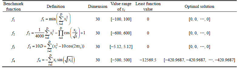
Table 4 Optimization comparison between DEA and AP-QDEA
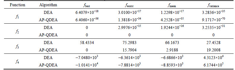
The maximum number of evolutional generation is 1500, and two algorithms are run separately for 30 times. The searching results of f1 show that fbest and fworst of AP-QDEA are better than those of DEA, and closer to the ideal function value 0. fmean of AP-QDEA is closer to 0, and fvariance is smaller than that of DE. It can be seen from Figs. 3(a) and (b) that under the same condition of evolutional generation, the convergence rate of AP-QDEA is faster than DEA, which makes it easier to get close to the ideal function value.
As searching for the optimal solutions of test function f2, the maximum number of evolutional generation is 1500, and two algorithms are run separately for 30 times. From the searching results of f2, it can be seen that the ideal result is not obtained every time when carrying out optimal solutions searching to f2 by DEA, which has sort of randomness. fbest, fworst, fmean and fvariance obtained by AP-QDEA are 0, which indicates that when carrying out optimal searching to f2 for 30 times by AP-QDEA, the ideal result can be obtained every time, which shows better stability. The convergence curves in Figs. 3(c) and (d) show that when AP-QDEA runs to 850 generations, the ideal optimal value is obtained. When DEA stops at 1500 generations, the optimal value has not converged to optimal solutions. Under the condition of the same generations, the convergence rate of AP-QDEA is faster than DEA, and the optimization result is closer to the ideal function value.
The maximum number of evolutional generation for f3 is 5000, and two algorithms run separately for 5 times, respectively. The maximum number of evolutional generation for f4 is 10000, and two algorithms run separately for 10 times, respectively. The results shown in Figs. 3(e) and (h) indicate that all the evaluation indexes of AP-QDEA are better than DEA, which reflects that the optimization performance of AP-QDEA is better than DEA.
In summary, AP-QDEA is obviously better than DEA, which has stronger global search ability and higher searching precision. The value of fmean and fvariance show that AP-QDEA has greater stability and robustness in the process of optimizing.
5 Simulation experiments
5.1 Parameter settings
The simulation experiments are conducted based on a certain type of parafoil system with the physical parameters given in Table 5.
Based on the selected parafoil system, basic motion parameters are set as: on the premise that the yaw angle is less than 20�� to maintain the flight stability, the initial velocity vs=13.8 m/s, vz=4.6 m/s, the minimum turning radius Rmin=100 m, the control quality corresponding to the minimum turning radius ��max=0.138, the scope of Rep is [245 m, 500 m], the direction of turning is clockwise d=1. The relevant parameters of AP-QDEA are set the same as Section 4.2.2, and the maximum number of evolutional generations is set as Gm=500.
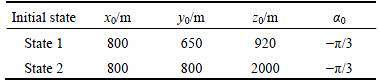
In order to comprehensively validate the applicability of the full height multiphase homing method, three kinds of initial states of parafoil system are set up for simulation, as given in Table 6, where (x0, y0, z0) denotes the initial position of parafoil system, and ��0 denotes its initial direction.
5.2 Simulation process
According to the preset parameters above, the object function of multiphase homing trajectory is optimized by AP-QDEA, and the simulation process is shown as follows:
Step 1: Initial AP-QDEA and other parameters related to the parafoil system and its multiphase homing trajectory.
Step 2: Initial main and auxiliary populations of Rep and ��ep, as well as their corresponding probability amplitude in main populations according to Eqs. (12)-(15) and Eq. (19).
Step 3: Evaluate the main population. Calculate the fitness function values of all the individuals of main population by using Eq. (3), and save the optimal individual.
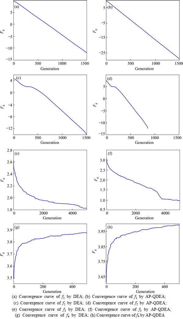
Fig. 3 Convergence curves of benchmark functions when using DEA and AP-QDEA:
Table 5 Design parameters of parafoil system
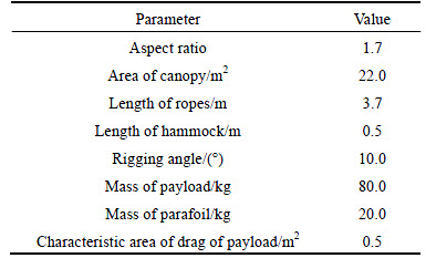
Table 6 Three kinds of initial states
Step 4: Complementary mutation. Select s individuals randomly from the main population, carry out complementary mutation operation on each component of s individuals, and record the optimal one.
Step 5: Carry out differential evolution to main and auxiliary populations according to Eqs. (20)-(25).
Step 6: g=g+1. Determine whether to stop algorithm according to the stop condition. If the condition is satisfied, the optimal individual Rep and ��ep are output. If not, the algorithm turns to Step 3.
Step 7: Substitute Rep and ��ep into Eqs. (4)-(10), and the relevant parameters of multiphase trajectory can be obtained, as well as the multiphase homing trajectory.
5.3 Simulation results
1) Simulation results of State 1
According to object function of the multiphase homing trajectory of parafoil system, and optimized by AP-QDEA, the optimal parameters of the multiphase homing trajectory are obtained as Rep=280.2965 m and ��ep=-1.9256. The curve of control quantity u is shown in Fig. 4, and the corresponding multiphase homing trajectory is planned by acting u on the particle model of parafoil system, as shown in Figs. 5 and 6.
2) Simulation results of State 2
According to object function of the multiphase homing trajectory of parafoil system, and optimized by AP-QDEA, the optimal parameters of the homing trajectory are obtained as Rep=428.7644 m and ��ep=-2.3180. Additionally, according to Eq. (9), n=2. The curve of control quantity u is shown in Fig. 7, and the corresponding multiphase homing trajectory is planned by acting u on the particle model of parafoil system, as shown in Figs. 8 and 9.
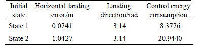
The total energy consumption, landing error and landing direction of two different kinds of initial state are given in Table 7.
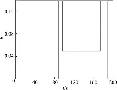
Fig. 4 Control quantity curve
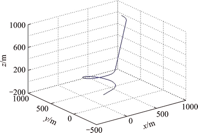
Fig. 5 Multiphase homing trajectory in 3D space
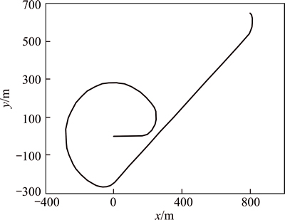
Fig. 6 Multiphase homing trajectory in horizontal plane
It can be seen from the data of homing results, the fixed-point homing and upwind landing in any sufficient height initial point can be realized by the AP-QDEA based multiphase homing trajectory planning scheme. From the view of control curve, it is a simple piecewise function and easy to implement. The control process is without frequent manipulation of motors. From the view of engineering implementation, this method does not require high control precision, which is conducive to the stability of the whole system.
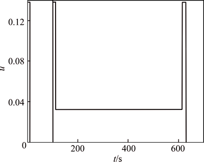
Fig. 7 Control quantity curve
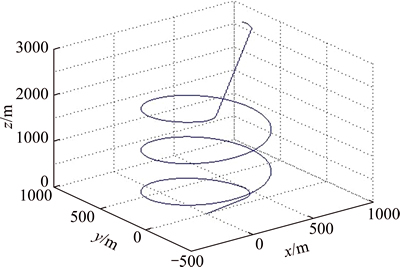
Fig. 8 Multiphase homing trajectory in 3D space
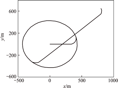
Fig. 9 Multiphase homing trajectory in horizontal plane
Table 7 Homing results
6 Conclusions
The homing trajectory design problem of parafoil system is discussed and a complete set of multiphase homing trajectory planning scheme is presented according to the maneuverability and basic flight characteristics of the vehicle. And a novel optimization algorithm named AP-QDEA is also given. In AP-QDEA, the crossover, mutation and integer coding of DEA are reserved with the advantages of strong adaptation and great global searching ability, while the probability amplitude coding and complementary mutation of QEA improve its local searching ability. Additionally, combining with the auxiliary population enhances the ability of escaping from local optimum and ensures the searching ability, searching precision and robustness of AP-QDEA. Furthermore, the proposed algorithm is applied as a tool to optimize the objective function based on the geometric relationship of each phase homing trajectory which is composed of arcs and straight lines. In order to confirm the capability and applicability of the proposed algorithm, two experiments with different initial states have been conducted. Simulation results show that AP-QDEA can fully guarantee the high precision and strong robustness in multiphase trajectory optimization, and the multiphase homing trajectory planning scheme can fulfill the requirement of fix-point and upwind landing in initial states with sufficient height greatly.
According to this research, the homing trajectory planning scheme is proven to be feasible for autonomous homing of parafoil system and the power of the proposed AP-QDEA has been revealed. Our future work will aim at improving homing trajectory planning schemes of parafoil system in any arbitrary initial states, especially in the case of insufficient height.
References
[1] ZHU Er-lin, SUN Qing-lin, TAN Pan-long, CHEN Zeng-qiang, HE Ying-ping. Modeling of powered parafoil based on kirchhoff motion equation [J]. Nonlinear Dynamics,2015, 79(1): 617-629.
[2] LI Chun, LU Zhi-hui, HUANG Wei, SHEN Chao. Guidance navigation & control system for precision fix-point homing parafoil [J]. Journal of Central South University: Science and Technology, 2012, 43(4): 1331-1335. (in Chinese)
[3] ROGERS J, SLEGER N. Robust parafoil terminal guidance using massively parallel processing [J]. Journal of Guidance, Control, and Dynamics, 2013, 36(5): 1336-1345.
[4] XIONG Jing. Research on the dynamics and homing project of parafoil system [D]. Changsha: National University of Defense Technology, 2005. (in Chinese)
[5] ZHANG Li-min, GAO Hai-tao, CHEN Zeng-qiang, SUN Qing-lin, ZHANG Xing-hui. Multi-objective global optimal parafoil homing trajectory optimization via gauss pseudospectral method [J]. Nonlinear Dynamics, 2013, 72(1/2): 1-8.
[6] GAO Hai-tao, ZHANG Li-min, SUN Qing-lin, SUN Ming-wei, CHEN Zeng-qiang, KANG Xiao-feng. Fault-tolerance design of homing trajectory for parafoil system based on pseudo-spectral method [J]. Control Theory & Applications, 2013, 30(6): 702-708. (in Chinese)
[7] JIAO Liang, SUN Qing-lin, KANG Xiao-feng. Route planning for parafoil system based on chaotic particle swarm optimization [J]. Complex Systems and Complexity Science, 2012, 9(1): 47-54. (in Chinese)
[8] Jann T. Aerodynamic model identification and GNC design for the parafoil-load system ALEX [J]. AIAA paper, 2001: 155-165.
[9] SOPPA U, STRANGH R. GNC Concept for automated landing of a large parafoil [R]. AIAA 97-175, 1997.
[10] ZHANG Xing-hui, ZHU Er-lin. Design and simulation in the multiphase homing of parafoil system based on energy confinement [J]. Aerospace Control, 2011, 29(5): 43-47. (in Chinese)
[11] ZHENG Chen, WU Qing-xian, JIANG Chang-sheng, XIE Ya-rong. Optimization in multiphase homing trajectory of parafoil system based on IAGA [J]. Electronics Optics & Control, 2011, 18(2), 69-72. (in Chinese)
[12] FAN Qin-qin, LU Zhao-min, YAN Xue-feng, GUO Mei-jin. Chemical process dynamic optimization based on hybrid differential evolution algorithm integrated with Alopex [J]. Journal of Central South University, 2013, 20(4): 950-959.
[13] SU Guo-shao, ZHANG Xiao-fei, CHEN Guang-qiang, FU Xing-yi. Identification of structure and parameters of rheological constitutive model for rocks using differential evolution algorithm [J]. Journal of Central South University of Technology, 2008(S1): 25-28.
[14] MOHAMMAD H, TAYARANI N, BENNETT P A, MOHAMMADI H. A novel magnetic update operator forquantum evolutionary algorithms [J]. Soft Computing in Industrial Application, 2011, 96: 67-76.
[15] Han K H, Kim J H. Quantum-inspired evolutionary algorithm for a class of combinatorial optimization [J]. Evolutionary Computation, IEEE Transactions on, 2002, 6(6): 580-593.
[16] CHOURAQUI S, BENZATER H. Multi-objective biogeography- basedoptimizationtechnique for tuning PUMA 560S controller [J]. Nonlinear Dynamics, 2015, 79(4): 2577-2588.
[17] JIAO Liang, SUN Qing-lin, KANG Xiao-feng, CHEN Zeng-qiang, LIU Zhong-xin. Autonomous homing of parafoil and payload system based on ADRC [J]. Journal of Control Engineering and Applied Informatics, 2011, 13(3): 25-31.
[18] STRANHAN A L. Testing of parafoil autonomous GN&C for X-38 [C]// 17th AIAA Aerodynamic Decelerator Systems Technology Conference and Seminar. Monterey, California, USA: AIAA, 2003: 19-22.
[19] GUO Peng. Research on improvement of differential evolution algorithm [D]. Tianjin: Tianjin University, 2011. (in Chinese)
(Edited by YANG Bing)
Foundation item: Project(61273138) supported by the National Natural Science Foundation of China; Projects(KJ2016A169, KJ2015A242) supported by the University Natural Science Research Key Project of Anhui Province, China; Project(ZRC2014444) supported by the Talents Program of Anhui Science and Technology University, China
Received date: 2015-08-27; Accepted date: 2015-11-10
Corresponding author: GAO Hai-tao, PhD; Tel: +86-18226670819; E-mail: gc_0532@126.com
Abstract: In order to realize safe and accurate homing of parafoil system, a multiphase homing trajectory planning scheme is proposed according to the maneuverability and basic flight characteristics of the vehicle. In this scenario, on the basis of geometric relationship of each phase trajectory, the problem of trajectory planning is transformed to parameter optimizing, and then auxiliary population-based quantum differential evolution algorithm (AP-QDEA) is applied as a tool to optimize the objective function, and the design parameters of the whole homing trajectory are obtained. The proposed AP-QDEA combines the strengths of differential evolution algorithm (DEA) and quantum evolution algorithm (QEA), and the notion of auxiliary population is introduced into the proposed algorithm to improve the searching precision and speed. The simulation results show that the proposed AP-QDEA is proven its superior in both effectiveness and efficiency by solving a set of benchmark problems, and the multiphase homing scheme can fulfill the requirement of fixed-points and upwind landing in the process of homing which is simple in control and facile in practice as well.
