

Dynamic measurement on infiltration process and formation mechanism of infiltration front
QI Le-hua(���ֻ�), XU Rui(�� ��), SU Li-zheng(������), ZHOU Ji-ming(�ܼ���), GUAN Jun-tao(�ؿ���)
School of Mechatronics, Northwestern Polytechnical University, Xi��an 710072, China
Received 3 August 2009; accepted 2 February 2010
Abstract:
An infiltration measurement device was developed to research the infiltration process of molten AZ91D magnesium alloy into the Al2O3 short fibre preform. The variation of relationship between the heights of measuring points and the time for molten alloy to reach the measuring points was illustrated. The effect of infiltration process parameters on the infiltration front was analyzed. It is found that pressure and pouring temperature are the most important factors which affect the infiltration velocity and composite quality. Furthermore, considering the influence of temperature field, an infiltration model of molten AZ91D into the short fibre preform was constructed on the basis of experimental results and Darcy��s Law. The analysis shows that the results predicted by this model are consistent with the experimental results.
Key words:
infiltration measurement; infiltration front; temperature field; infiltration model;
1 Introduction
As an indispensable step in the fabrication technologies of metal matrix composites (MMC), the liquid metal infiltration process in porous preform, such as squeeze casting, vacuum infiltration, variable pressure infiltration and liquid infiltration-extrusion, have attracted research interest due to significantly effective improvement in the properties of composite products [1-3]. Much research work was published on the investigation of the infiltration process of liquid metal into porous preform[4-6]. SCHULZ and KAUFMANN [7], and MATSUNAGA et al[8] designed an infiltration device to control the process parameters of gas pressure infiltration. MORTENSEN et al[9-10] described fluid flow and heat transfer during the liquid metal infiltration process and a kinetics model was presented. But few studies were reported on the experimental research of internal infiltration process.
The methodology for the experimental investigation of infiltration process mainly includes two ways at present. One is a direct observation by visualization mould and transparent fiber and the other adopts the way of physical simulation to analyze low-pressure infiltration process based on the similarity principle. For example, TURNER et al[11] investigated the injection process of glass fibre reinforced plastic by visualizing the filling process. YOKOI et al[12-14] analyzed the shifting phenomenon of melt forefront during multi-cavity injection molding process with a visualization mould. HE et al[15-16] used a suitable liquid and filler particles at room temperature to simulate low-pressure infiltration process of high- temperature aluminum melt in porous media in an organic transparent device. However, the methods are difficult to reflect the actual infiltration process due to the high temperature condition and the opacity of the preform during liquid infiltration processes for MMC fabrication. LONG et al[17] and EARDLEY et al[18] obtained the changing information of temperature during the infiltration process with thermocouples which were inserted into the preform. It should be noted that the porous structure of preform is damaged in this way. As a result, the infiltration regularity will be changed.
In this work, the measurement device for negative pressure infiltration was developed. It acquires the change of temperature information during the infiltration process of liquid magnesium alloy into Al2O3 preform by utilizing a self-designed sleeve. The dynamic evolution of infiltration process was visualized by analyzing the temperature data. Furthermore, considering the influence of temperature field, a flow model of molten magnesium alloy was constructed on the basis of experimental results and Darcy��s law.
2 Experimental
2.1 Experimental material
AZ91D magnesium alloy was used in the experiments as matrix, and the compositions and properties are given in Table 1. The compositions and properties of short Al2O3 fiber for preparing preform are shown in Table 2.
Table 1 Compositions and properties of AZ91D magnesium alloy

Table 2 Compositions and properties of Al2O3 fibre
![]()
Wet forming process was used to prepare preform. Firstly, proper amounts of binder and dispersant were added into the fibre solution. Secondly, Al2O3 fiber dispersion was poured into the forming die and drained under pressure. Finally, the preform was formed. The process is illustrated in Fig.1.
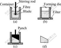
Fig.1 Schematic diagram of process of preparing preform
After mould pressing, the preform was dried for 24 h at room temperature, and subsequently dried in an oven at 250 �� for 4 h. Finally, short Al2O3 fibre preform with certain compressive strength was obtained, and the morphology is shown in Fig.2.

Fig.2 Macrostructure of Al2O3 preform prepared by wet forming process
2.2 Experimental device
Fig.3(a) shows the schematic diagram of the developed infiltration measurement device. It is assembled by infiltration systems, pressure control system, temperature control system, vacuum system and temperature measurement system. The pressure control system precisely governs the pressure of crucible within 0-1 MPa by adjusting the inlet valve, so that the liquid magnesium alloy infiltrates into the Al2O3 fibrous preform. Temperature control system is used to melt AZ91D magnesium alloy and preheat short Al2O3 fibre preform. The degree of vacuum in infiltration process is ensured by the vacuum system. A high-precision thermocouple with a diameter of 1 mm is used in the temperature measurement system to obtain the temperature information during infiltration process. Thermocouples are inserted into the stainless steel tube and contact closely with the inclined plane of sleeve through the hole located on the positioning cover. The distribution of the located hole on the positioning cover is shown in Fig.3(b). Temperature variations during the infiltration process of liquid AZ91D alloy into porous preform were obtained from nine high-precision thermocouples on the inclined plane of sleeve.
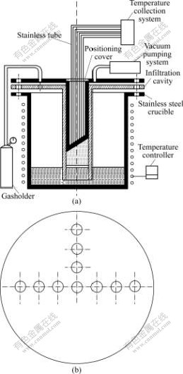
Fig.3 Scheme of experimental facility and thermocouple locations: (a) Infiltration measurement device; (b) Vertical view of positioning cover
2.3 Experimental method
The inclined plane of sleeve contacts with the preform in the infiltration process. When liquid magnesium alloy reached the inclined plane of preform, temperature changed on the corresponding location of the inclined plane. This information can be captured by using the high-precision thermocouple. Due to the axial gradient of preform, the changing temperature information reflected the infiltration process of porous preform by molten magnesium metal. The variation of relationship between the heights of measuring points and the time of corresponding height was obtained based on analyzing the temperature information.
Fig.4 shows the distribution of the measuring points on the inclined plane of preform. The temperature information of infiltration process was recorded from nine measuring points, six of which are in axial direction and four are in radial direction. The change of temperature information on the height of preform can be obtained at the six measuring points in axial gradient. Take point K as the starting position of infiltration, the variation of relationship between the height of measuring points and the time to reach the corresponding height with different process parameters was obtained.
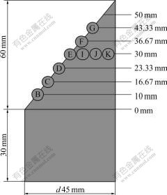
Fig.4 Schematic distributions of measuring points in Al2O3 preform
3 Results and discussion
3.1 Analysis on infiltration process of liquid magnesium alloy into Al2O3 preform
Relationships between heights of measuring points and the time that melted alloy reaches the monitored points are illustrated in Fig.5, which were drawn from the temperature records of thermocouples inserted in the inclined plane of preform along the axial and radial direction. It was shown that magnesium alloy melt moved fast along the path from point C to D, and it took longer time to infiltrate from point F to G at the same condition of 0.4 MPa and 800 ��. This means that the instable infiltration occurred at the above mentioned condition. Fortunately, stable infiltration can be obtained by increasing pressure and decreasing melt temperature, which can be seen from Figs.5(b)-(c). In other words, time for infiltration from point C to D is nearly equal to that from point F to G.
Fig.5 shows that the molten magnesium firstly reached point K in preform edge, and then reached point B, finally the core region E, where the temperature was the lowest. This was because the preheating temperature of preform decreased from the edge point K to the core point E during the preheating process, as shown in Fig.6. The cooling rate of the liquid magnesium alloy in the preform increased owing to the decrease of preheating temperature in the core position E, which resulted in the viscosity and the viscosity resistance of liquid magnesium alloy becoming larger to slow down the flowing velocity of molten metal. However, the flowing velocity in the edge region of the preform was fast due to the high preheating temperature. On the other hand, part of the liquid alloy was solidified during rapid cooling by the fiber when the preheating temperature of infiltration process was lower. Thus, the flow channel of the liquid magnesium alloy was reduced significantly or blocked completely, so that the required infiltration pressure increased or even completely prevented further infiltration of liquid magnesium alloy. As a result, the liquid magnesium reached the edge region first where the temperature was high, and then arrived to the core location where the temperature was lower.
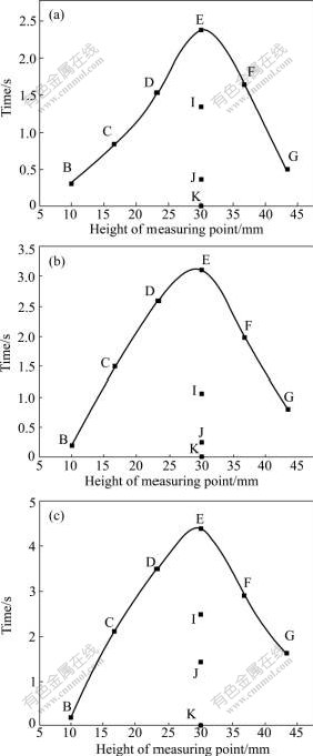
Fig.5 Curves of measuring points heights and time for alloy melt to reach monitored points at different conditions: (a) 0.4 MPa, 800 ��; (b) 0.5 MPa, 780 ��; (c) 0.6 MPa, 760 ��
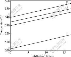
Fig.6 Experimentally measured temperature of preform in radial direction
The average velocity of corresponding infiltration heights was calculated by the curves of measuring heights and the time to reach monitored points shown in Fig.5. Due to the small interval distance of axial thermocouples, average velocity was used to substitute instantaneous infiltration velocity for analysis. Fig.7 shows the fitting curve between height of measuring points and average infiltration velocity under different infiltration pressures. As shown in Fig.7, instable flow and large velocity fluctuation occurred under low pressure and high temperature. The fluctuation of velocity reached its maximum when the pressure was 0.4 MPa and the pouring temperature was 800 ��. With the increase of pressure and the decrease of temperature, the fluctuation of velocity became smaller and reached its minimum under the pressure of 0.6 MPa and the pouring temperature of 760 ��, which meant that the infiltration became stable. The infiltration velocity became small with the decrease of pouring temperature under the pressure of 0.6 MPa. Through the above analysis, it is concluded that the infiltration became stable with the increase of pressure and the decrease of temperature. The infiltration velocity became fast with the increase of pouring temperature. Fig.8 shows the selected core location (as indicated by point A) on the sample for SEM analysis to investigate the infiltration quality with different process parameters. As shown in Fig.9, large amount of micro-pores with a size of about 100 ��m existed in the composite under the pressure of 0.4 MPa and the pouring temperature of 800 ��. Based on the analysis of Fig.7, large velocity fluctuation occurred under low pressure and high temperature, and this involved a lot of gas during the infiltration process, which causes a large amount of micro-pores in the composite. The infiltration became stable with the increase of pressure and the decrease of temperature, therefore, the number of micro-pores in the composite decreased and the pores became smaller. The microstructure and fibre distribution also became uniform. No significant porosity defects were found in the composite when the pressure was up to 0.6 MPa and the pouring temperature was 760 ��.
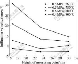
Fig.7 Relationship between height of measuring points and infiltration velocity
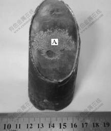
Fig.8 Selected position for SEM analysis in infiltration sample
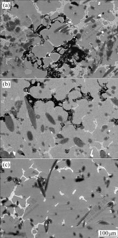
Fig.9 SEM images of selected sample position: (a) 0.4 MPa, 800 ��; (b) 0.5 MPa, 780 ��; (c) 0.6 MPa, 760 ��
3.2 Formation mechanism of infiltration front of Al2O3 preform by liquid magnesium alloy
In order to analyze the formation mechanism of the infiltration front, an infiltration model according to the practical situation was created which was based on the influence of temperature field during the infiltration process of liquid magnesium alloy into Al2O3 preform.
Fig.10 shows the principle of this model which divides the infiltration process into three regions, that is, liquid metal region, infiltration region and non- infiltration region. The liquid magnesium infiltrates into the fibrous preform under pressure from the bottom of the preform.
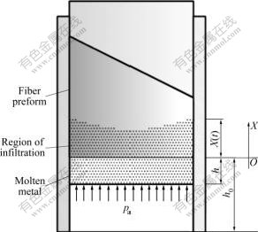
Fig.10 Schematic diagram of infiltration model of molten AZ91D into short fibre preform
The Reynolds number of liquid magnesium alloy infiltrating in the Al2O3 preform was 0.456 on the basis of calculation, which is less than 5. The flow of molten metal in the preform is in accordance with the application scope of Darcy's Law. It is assumed that the liquid metal is an incompressible homogeneous fluid. The dependence of the infiltration velocity u, on the pressure gradient can be described as[19]:
![]() (1)
(1)
where k and �� are the permeability of the perform and the viscosity of the liquid metal, respectively; and ��p is the pressure gradient.
According to the infiltration process of molten metal shown in Fig.10, Darcy��s law can be expressed as:
![]() (2)
(2)
where ��f is the volume fraction of fibres. Here the ��bundles of capillaries�� model is used. Where ��f is the volume fraction of fibre. In this case, the permeability k and ��Pi are expressed by [20]:
 (3)
(3)
where �� is the density, g is the acceleration of gravity, h is the infiltration height at 0 s, x is the infiltration height at t s, n and r are the porosity of the fibre preform and the effective capillary tube radius of the fibre perform, respectively, and r is calculated 7.5 ��m using the first model in Ref.[21]. pa is the external pressure applied to the liquid metal, p�� is the additional pressure caused by viscous resistance, p��=8��ux/r2 according to the Poiseuille Law, pc is the capillary pressure at the infiltration front, pe is the tip resistance, pe=-��u2/4, and pv is the pressure of infiltration front.
The capillary pressure pc is given by the following Yong-Kelvin equation:
![]() (4)
(4)
where ��lv is the surface tension of the liquid metal and �� is the contact angle between the liquid metal and the preform material.
Considering h+x=h0+��f x, u=dx/dt, and introducing it into Eq.(2), Eq.(5) is obtained:
![]()
![]() (5)
(5)
In order to simplify the solution, the model is simplified and small resistance is neglected, such as pe.
Considering ��f��0.2, the changing in the height of the liquid metal is ignored. On the assumption that h0+ ��fx=h0, the variation relationship of the kinetic viscosity coefficient with the changing temperature is expressed in Eq.(6), including the influence of temperature field.
 (6)
(6)
In Eq.(5), R is gas constant, T is absolute temperature, ��0 and E are material constants. For magnesium alloy, ��0 is 45 and E is 30 500 MPa[22-23].
when pa is constant, x=0 and t=0, the solution to Eq.(6) is
![]() (7)
(7)
In the present experiment, the volume fraction of fiber preform is 10%, the effective capillary tube radius of the fiber preform is 8 ��m, and surface tension of the molten magnesium ��lv=0.6 N?m. Introduce these parameters into Eq.(7) and ignore the influence of��gh0, the relationship among infiltration pressure pa, pouring temperature T and infiltration height x is obtained when the infiltration time is 2.5 s, as shown in Fig.11. In order to verify the accuracy of the model, predicted values are compared with experimental values. The deviation between simulation value and experiment value of the infiltration height is about 9%. The analysis shows that the predicted results of infiltration front by this model have a good agreement with the experimental results. In addition, it can be seen from Fig.11 that there is a minimum pressure during the infiltration process, which is the threshold infiltration pressure. The infiltration process is unable to be carried out when the applied pressure is less than the threshold infiltration pressure.
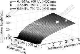
Fig.11 Coupled relationship among infiltration pressure pa, pouring temperature T and infiltration depth x
4 Conclusions
1) The infiltration becomes stable and the fluctuation of velocity becomes smaller with the increase of pressure and the decrease of pouring temperature. The infiltration velocity becomes fast with the increase of pouring temperature.
2) The number of micro-pores in the composite decreases and the pores become smaller with the increase of pressure and the decrease of pouring temperature. Microstructure and fibre distribution become more uniform without significant porosity defects in the composite when the pressure is up to 0.6 MPa and the pouring temperature is 760 ��.
3) Considering the effect of temperature field, a flow model of molten AZ91D into the short fiber preform was constructed to describe the formation mechanism of the infiltration front. The deviation between simulation value and experiment value of the infiltration height is about 9%.
References
[1] KAPTAY G. The threshold pressure of infiltration into fibrous preforms normal to the fibres�� axes [J]. Composites Science and Technology, 2008, 68(1): 228-237.
[2] QI Le-hua, ZHOU Ji-ming, SU Li-zheng, OUYANG Hai-bo, LI He-jun. Fabrication of Csf/Mg composites using extrusion directly following vacuum infiltration-Part 2: Forming process study [J]. Solid State Phenomena, 2008, 141/143: 91-96.
[3] HU Lian-xi, YANG Yi-wen, LUO Shou-jing, XU Xin-ying. Kinetics of infiltration of liquid aluminum into alumina fibrous preform [J]. The Chinese Journal of Nonferrous Metals, 1998, 8(s1): 75-79. (in Chinese)
[4] QI Le-hua, CUI Pei-ling, LI He-jun. Numerical simulation of infiltration process in liquid extrusion for fabrication of Al2O3f/LY12 composites [J]. The Chinese Journal of Nonferrous Metals, 2000, 10(1): 141-144. (in Chinese)
[5] OUYANG Hai-bo, LI He-jun, QI Le-hua, LI Zheng-jia, FANG Ting, WEI Jian-feng. Fabrication of short carbon fibre preforms coated with pyrocarbon/SiC for liquid metal infiltration [J]. Journal of Materials Science, 2008, 43(13): 4618-4624.
[6] QI Le-hua, SU Li-zheng, JIANG Chun-xiao, ZHOU Ji-ming, LI He-jun. Research on the numerical simulation of liquid-infiltration-extrusion process for composites based on the rigid-viscoplastic FEM [J]. Materials Science and Engineering A, 2007, 454/455: 608-613.
[7] SCHULZ P, KAUFMANN H. Fabrication of carbon fibre reinforced Al-inserts for local reinforcement of automotive components [C]. ISATA, 32nd ISATA Symposium Proceedings: Materials for Energy��Effective Vehicles. UK, 1999: 185-192.
[8] MATSUNAGA T, OGATA K, HATAYAMA T, SHINOZAKI K, YOSHIDA M. Effect of acoustic cavitation on ease of infiltration of molten aluminum alloys into carbon fibre bundles using ultrasonic infiltration method [J]. Composites, 2007, 38(1): 771-778.
[9] MORTENSEN A, MASUR L, CORNIE J, FLEMINGS M C. Infiltration of fibrous preforms by a pure metal: Part I. Theory [J]. Metallurgical Transactions, 1991, 20A(11): 2535-2547.
[10] MICHAUDA V, MORTENSEN A. On measuring wettability in infiltration processing [J]. Scripta Materi, 2007, 56(10): 859-862.
[11] TURNER D Z, HJELMSTAD K D, LAFAVE J M. Three- dimensional flow visualization experiment of an RTM injection for a GFRP cuff mold [J]. Composite Structures, 2006, 76(4): 352-361.
[12] YANG W M, YOKOI H. Visual analysis of the flow behavior of core material in a fork portion of plastic sandwich injection molding [J]. Polymer Testing, 2003, 22(1): 37-43.
[13] JIANG Kai-yu, YOKOI H. Experiment study on filling imbalance phenomenon of melt front during injection molding process [J]. Chinese Journal of Mechanical Engineering, 2009, 45(2): 294-300. (in Chinese)
[14] CHEN Jing-bo, SHEN Chang-yu, YOKOI H. Experimental study on filling imbalance in multi-cavity injection mold [J]. Chinese Journal of Mechanical Engineering, 2007, 43(10): 170-174. (in Chinese)
[15] HE De-ping, HE Si-yuan, GU Fei-fei, HUANG Ke. The infiltration process of Al-alloy-melt��s into porous medium and porous aluminum alloy [J]. Science in China (Series B: Chemistry), 2009, 39(1): 22-30. (in Chinese)
[16] LIU Bing, HE Si-yuan, HE De-ping. The two-dimension tube model of Al-alloy-melt��s infiltration in porous medium [J]. Chinese Journal of Materials Research. 2006, 20(4): 389-393. (in Chinese)
[17] LONG S, ZHANG Z, FLOWER H M. Characterization of liquid metal infiltration of a chopped fibre preform aided by external pressure-I. Visualization of the flow behavior of aluminium melt in a fibre preform [J]. Acta Metall Mater, 1995, 43(9): 3489-3498.
[18] EARDLEY E S, FLOWER H M. Infiltration and solidification of commercial purity aluminium matrix composites [J]. Materials and Engineering A, 2003, 359: 303-312.
[19] HU Lian-xi, YANG Yi-wen, LUO Shou-jing, XU Xin-ying. Investigation on the kinetics of infiltration of liquid aluminium into an alumina fibrous preform [J]. Journal of Materials Processing Technology, 1999, 94(2/3): 227-230.
[20] BEAR J. Dynamics of fluids in porous media [M]. New York: Elsevier, 1972.
[21] LUO Shou-jing. Liquid infiltration extrusion of composites [M]. Beijing: Metallurgical Industry Press, 2002: 118-120. (in Chinese)
[22] SMITHELLS C J. Smithells metals reference book [M]. 6th Ed. London: Butterworths, 1983.
[23] GARCIA-CORDOVILLA C E L, NARCISO J. Pressure infiltration of packed ceramic particulates by liquid metals [J]. Acta Materialia, 1999, 47(18): 4461-4479.
Foundation item: Project(50575185) supported by the National Natural Science Foundation of China; Project(CX201011) supported by the Doctorate Foundation of Northwestern Polytechnical University
Corresponding author: QI Le-hua; Tel: +86-29-88460447; E-mail: qilehua@nwpu.edu.cn
DOI: 10.1016/S1003-6326(09)60245-4
(Edited by FANG Jing-hua)
Abstract: An infiltration measurement device was developed to research the infiltration process of molten AZ91D magnesium alloy into the Al2O3 short fibre preform. The variation of relationship between the heights of measuring points and the time for molten alloy to reach the measuring points was illustrated. The effect of infiltration process parameters on the infiltration front was analyzed. It is found that pressure and pouring temperature are the most important factors which affect the infiltration velocity and composite quality. Furthermore, considering the influence of temperature field, an infiltration model of molten AZ91D into the short fibre preform was constructed on the basis of experimental results and Darcy��s Law. The analysis shows that the results predicted by this model are consistent with the experimental results.
