

J. Cent. South Univ. (2019) 26: 2528-2542
DOI: https://doi.org/10.1007/s11771-019-4192-6

Flow pattern and pressure drop of gas-liquid two-phase swirl flow in a horizontal pipe
RAO Yong-chao(������)1, 2, DING Bo-yang(������)1, 2, WANG Shu-li(������)1, 2,WANG Zi-wen(������)1, 2, ZHOU Shi-dong(��ʫ�)1, 2
1. Jiangsu Key Laboratory of Oil-gas Storage and Transportation Technology, Changzhou 213016, China;
2. School of Petroleum Engineering, Changzhou University, Changzhou 213016, China
 Central South University Press and Springer-Verlag GmbH Germany, part of Springer Nature 2019
Abstract:
The gas-liquid two-phase swirl flow can increase the gas-liquid two-phase contact area and enhance the heat and mass transfer efficiency between gas and liquid. The swirl flow has important practical application value for promoting gas hydrate formation and ensuring the flow safe of natural gas hydrate slurry. The experimental section was made of plexiglass pipe and the experimental medium was air and water. The flow pattern of the gas-liquid two-phase swirl flow in the horizontal pipe was divided, according to a high-definition camera and the overall characteristics of the gas-liquid interface. The flow pattern map of the gas-liquid two-phase swirl flow in a horizontal pipe was studied. The influence of the flow velocity and vane parameters on pressure drop was investigated. Two types of gas-liquid two-phase swirl flow pressure drop models was established. The homogeneous-phase and split-phase pressure drop models have good prediction on swirl bubble flow, swirl dispersed flow, swirl annular flow and swirl stratified flow, and the predictive error band is not more than 20%.
Key words:
swirl flow; two-phase flow; flow pattern; swirl number; pressure drop��
Cite this article as:
RAO Yong-chao, DING Bo-yang, WANG Shu-li, WANG Zi-wen, ZHOU Shi-dong. Flow pattern and pressure drop of gas-liquid two-phase swirl flow in a horizontal pipe [J]. Journal of Central South University, 2019, 26(9): 2528-2542.
DOI:https://dx.doi.org/https://doi.org/10.1007/s11771-019-4192-61 Introduction
The gas-liquid two-phase swirl flow is a swirl movement, which includes gas and liquid moving axially and tangentially (or circumferentially). The gas-liquid two-phase swirl flow is widely applied in the areas of power, chemical, oil and nuclear industry, and so on. The accurate predictions of internal two-phase flow pattern and pressure drop investigations are very important for developing the related application fields and designing the industrial equipment [1-3].
For flow pattern, through the unremitting efforts of scholars from various countries, some classic flow pattern maps in the horizontal pipe have been proposed. Such as Baker flow pattern map [4], Mandhane flow pattern map [5], Taitel flow pattern map [6], Weisman flow pattern map [7], Hewitt flow pattern map [8], Weisman flow pattern map [9], and Barnea flow pattern map [10-13]. However, there are few studies on flow pattern of gas-liquid two-phase swirl flow, due to some swirl flow decay.
For pressure drop, the two-phase flow is essentially different from single-phase flow. Unlike single-phase flow, there was a phase interface in the two-phase flow. There was the interaction force between the fluid and the pipe wall in the two-phase flow, and there was also the force between the two phases. There was the energy exchange between the fluid and the pipe wall in the two-phase flow, and there was the energy exchange between the two phases. The energy exchange exacerbates the mechanical energy loss. Experiment shows that the pressure loss of multi-phase flow was much larger than single-phase flow. Under similar flow conditions, the former can be 5-10 times more than the latter [14]. At present, domestic and foreign scholars have conducted a lot of research on the pressure drop characteristics of multi-phase flows in horizontal pipe, and some pressure drop calculation models have been applied. Next, the pressure drop characteristics of the gas-liquid two-phase flow and gas-liquid two-phase swirl flow were analyzed separately.
For the pressure drop calculation of the gas- liquid two-phase flow in a horizontal pipe, the separated flow model proposed by LOCKHART and MARTINELLI (L-M) [15] and CHISHOLM [16] was the more widely applied. The L-M relation was based on the experimental data of air and several liquids in a horizontal pipe under normal pressure. The L-M relation was suitable for low flow velocity. The limitation of this method was that the influence of mass velocity, pipe diameter, pressure, and flow direction on the frictional pressure drop was not considered. Therefore, there would inevitably be great deviations when the L-M relation was applied to different flow conditions. In 1967, CHISHOLM [17] obtained experimental data charts for the split-liquid-phase conversion coefficients from the experiments, and the value of C can be directly found out based on the experimental conditions which greatly facilitates the application of the relation, and the CHISHOLM C relation was derived. Through experimental research, CHISHOLM divided the values of C into 5, 10, 12 and 20, respectively, for engineering applications according to the gas-liquid components. With the in-depth study of the pressure drop characteristics of two-phase flow in different fields and the rapid development of nuclear engineering technology, miniaturization of heat exchangers, chemical engineering, refrigeration technology, and microelectronics and microcirculation, the more accurate and universal two-phase frictional pressure drop was demanded. Some researchers found that the parameter C needed to be corrected in order to predict the more accurate pressure drop. BAKER [4] also studied the pressure drop of oil and gas mixed transmission pipelines. First, a flow pattern was recommended, and then different calculation formulas were adopted according to different flow patterns. In general, Baker��s method was generally better for larger pipe diameters (D��150 mm), and it was more accurate for slug flow, but it was less effective for other flow patterns. In addition, pressure drop should be calculated according to the pressure drop formula corresponding to the two or even three types of flow patterns near the boundary, and the best one was finally selected from them. TAITEL et al [6] summarized a large number of published experimental data, and proposed DUKLER��s first method and DUKLER��s second method. For DUKLER��s first method, it was assumed that the fluid was a gas-liquid two-phase non-slip homogeneous mixture, the flow pattern was not to be determined, and the calculation was relatively simple. For DUKLER��s second method, the gas- liquid two-phase slippage was considered, DUKLER��s second method was suitable for large or small pipe. When the pipe diameter is large, the result will be better, and the accuracy was better than DUKLER��s first method. CHEN et al [18] carried out experiments on the friction of the gas- liquid two-phase flow in the pipe. A simple method for calculating the pressure drop of two-phase flow was obtained based on the experimental data and the homogenous model. Compared with the phase-flow model proposed by CHISHOLM, the result was more accuracy.
For the pressure drop of the gas-liquid two- phase swirl flow in the horizontal pipe, the calculation of pressure drop was different from the gas-liquid two-phase flow, because of tangential velocity in the swirl flow. For pressure drop calculation in the single-phase flow, the flow pattern (laminar flow or turbulent flow) was mainly determined by the Reynolds number, and then the Darcy��s law or other empirical formula for hydraulic friction in turbulent conditions was selected. However, if two-phase pressure drop calculation model was directly applied to swirl flow, a large deviation would inevitably occur. The decay of the swirl number has long been investigated in the single phase swirling flow [19, 20]. The swirl decay in the single phase swirl flow is characterized by the parameter of swirl number which can be expressed in various ways [21]. HORRI et al [22] used their own designed swirl flow device to conduct a preliminary study on swirl flow. In a similar way, flow patterns should also present significant influence on frictional pressure drop inside pipes containing twisted-tapes. As far as the present authors know, the only study describing flow patterns inside pipes with twisted-tapes was presented by KANIZAWA et al [23]; therefore predictive methods that take into account the flow pattern influence are still unavailable. In their study, KANIZAWA et al [24] have defined the following flow patterns: plug flow, slug flow, stratified flow and annular flow. JESUS et al [25] and MULLER et al [26] studied the pressure drop characteristics in the horizontal pipe and found that the flow pattern played a crucial role in pressure drop. FABIO et al [27] conducted a gas-liquid two-phase swirl flow experiment to study the factors affecting the law of pressure drop and found that the flow pattern was also the main factor affecting the pressure drop. SUN et al [28, 29] studied the distribution characteristics of the circumferential flow velocity and axial flow velocity at the outlet section of the swirl flow swirler, and analyzed its formation mechanism. ZOHIR et al [30] studied the flow pressure drop characteristics of the air current in a bulged pipe. The study showed that the installation position of the swirler had a great influence on the flow pattern, and the flow pressure drop with the swirler is 1.5 times that of no-swirl flow. FABIO et al [31] conducted experiments on the heat transfer coefficient and pressure drop of R-134a refrigerant in the horizontal pipe, and the results showed that compared with experimental data in the horizontal flow pipeline, heat transfer coefficient increase and pressure drop loss reached 36% and 133% respectively by the twisted tape. WANG et al [32-36] also conducted exploratory studies on the gas-liquid two-phase flow in horizontal pipe. SHYY et al [37] studied the swirl flow heat transfer characteristics and pressure drop characteristics in the injection state. The experimental results show that the viscosity coefficient and pressure drop gradually increased with the increase of the flow, and the pressure drop coefficient increased significantly compared with the no-swirl flow. FEI et al [38] invented a new pneumatic conveyer system with different lengths of fins on the front of horizontal pipes to reduce energy consumption and transmission speed, and carried out relevant experimental research, focusing on the energy consumption and pressure drop characteristics change in the condition of the pneumatic conveying system which has different length of fins. The experimental results show that compared with the traditional pneumatic conveyer system, the energy consumption and pressure drop have different reductions under the same transmission efficiency.
In summary, many scholars have studied the pressure drop characteristics in the gas-liquid two- phase swirl flow, and the research on pressure drop characteristics in the horizontal pipe has also been relatively mature, but the flow pattern, flow pattern map, flow law and pressure drop characteristics of swirl flow, especially the establishment of pressure drop model in the horizontal pipe, are still lacking. Therefore, the flow pattern and pressure drop characteristics of the gas-liquid two-phase swirl flow in a horizontal pipe should be studied using air and water, and the investigation will provide a new idea for the pressure drop calculation of the multi- phase flow, and also provide a theoretical support for the pipe hydrate slurry swirl flow technology.
2 Experiments
2.1 Experimental apparatus
As shown in Figure 1, the experimental device consists of four systems which includes a water circulating system, an air supply system, an image collecting system, and the experimental pipe. Water is pumped from the water tank, gas flow is controlled by the ball valve, liquid flow is measured by weighing method and liquid rotameter.
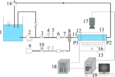
Figure 1 Schematic view of gas-liquid two-phase swirl flow experimental apparatus (1��Water tank; 2��Pump; 3��Control valve; 4��Piezometer; 5��Thermometer; 6��Flowmeter; 7��Check valve; 8��Air and liquid mixer;9��Air compressor; 10��Solenoid valve; 11��Swirl device; 12��Hyaline pipe; 13��Square model box; 14��Gas liquid separator; 15��Pressure measuring device; 16��Daylight lamp; 17��Vidicon; 18��Data acquisition instrument; 19��Computer)
Pressurized air is from the air compressor, the gas is mixed with water, and gas and liquid phase enter into experimental device. The gas phase flow is measured by glass rotor flowmeter. When the experiments finish, gas flows into the atmosphere, water flows into the water tank.
The water circulating system mainly consists of a pump, a liquid rotameter, and a regulating valve. The pump is single-phase submersible pump; the rated flow is 15 m3/h; the lift is 10m; the output shaft power is 0.75 kW. The air supply system consists of an air compressor, an air storage tank, a reducing valve, a piezometer, a gas rotameter, a check valve, a ball valve and a sluice valve. Air compressor is of PUMA piston; the exhaust pressure is 0.9 MPa; air tank capacity is 23 L; the rated speed is 120 r/min. There are two gas rotameters; the ranges are from 0.06 to 0.6m3/h and from 0.2 to 2.5 m3/h. The superficial velocities are 0-3.4 m/s for gas, and 0-2.7 m/s for water, respectively. The air voids varies from 10% to 90%. Image acquisition system mainly consists of illuminating system and a camera; the illuminating system uses 6500 K color temperature fluorescent pipe lighting, light stability, flicker free. Image recording system uses the SONY HDR-XR550E high-definition hard disk video camera. The experimental section consists of a hyaloid canal, a square box, a swirl flow generator and a pressure measuring device. The transparent pipe is a circular pipe with an inner diameter of d=23 mm, a wall thickness of 3.5 mm, and a length of 2000 mm; the distance between swirl device and inlet is 8d. The distance between pressure measurement point P1 and inlet is 4d. The distance between pressure measurement point P2 and outlet is 4d, which is made of a transparent organic glass pipe, to facilitate visual observation carried out on the experimental phenomena. The boundary of the experimental section is not flat; at the same time of image shoot, circular edge wall will have a convex mirror effect, which makes various points within the same field of view focus on different levels. So a square box made of transparent glass is added outside the transparent pipe, and distilled water is filled in the box to reduce refraction phenomenon and compensate the optical path.
2.2 Swirler
Figure 2 shows nine swirl vanes with three different vane areas and three different swirl angles. All vanes are used to perform the orthogonal tests. The vane size is expressed by the fraction of a single blade against the whole vane area, which equates 33.3%, 27.8% and 22.2%, respectively. The swirl angle is the angle between the single blade and the vane, which is expressed by a half of the angle between two blades. The swirl angles used in the experiments are 7.5��, 15�� and 22.5��, respectively, as shown in Table 1.
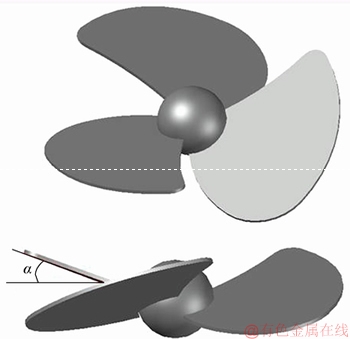
Figure 2 Schematic diagrams of swirl vanes
Table 1 Vane size and swirl angles of different vanes

3 Experimental results
3.1 Flow pattern
Different flow structures (flow pattern) appeared when the differing inflow of gas and liquid streams was routed simultaneously into the pipe. The typical flow pattern of gas-liquid two- phase swirl flow is shown in Figures 3(a) and (b). The gas-liquid two-phase swirl flow pattern changed obviously with the varying geometric parameters of the vane, the air inflow, the fluid inflow and the pipe length, because of the combinative centrifugal force. In addition, the distance between the rotating devices and flow pattern observation point was connected with the stability and changes of the flow pattern. Therefore, in order to guarantee the stability of the flow pattern, the stable flow pattern in the experimental pipe central section was defined as representative flow pattern in the condition of gas and liquid superficial velocity. In this work, the flow patterns occurring in the experiments were classified into the swirl wavy stratified flow, the swirl bubble flow, the swirl slug flow, the swirl annular flow, and the swirl dispersed flow.

Figure 3 Typical flow pattern of gas-liquid two-phase swirl flow:
Typical flow patterns are shown in Figures 4-8 and the schematic diagram of typical flow pattern is shown in Figure 9.
Swirl stratified flow (SS1): This flow pattern often appeared at low liquid superficial velocity and at high gas superficial velocity, as shown in Figure 4, and also took place in the later segment of pipe at high gas and liquid superficial velocity. The gas-liquid two-phase layered flow was regarded as a criterion. The two-phase boundary appeared on the wavy curved surface as there was a density difference between the two phases, and the gas flowed swirl along the upper side of the pipe and the liquid flowed swirl along the bottom side of the pipe under the influence of swirl centrifugal force.
Swirl bubble flow (SB): This flow pattern appeared when the gas superficial velocity was very low and the liquid superficial velocity outweighed the gas superficial velocity, as shown in Figure 6. When the gas inflow was low, the continuous gas stream was dispersed into smaller bubbles under the influence of liquid flow, as shown in Figure 5.
Swirl slug flow (SS2): This flow appeared at low liquid superficial velocity and high gas superficial velocity or at the back end of pipe when both the two-phase superficial velocities were high, as shown in Figure 6. The swirl flow moved along the pipe axis in the form of large bubbles or flow group within a small swirl range. The distance and range of this flow decreased with a reducing gas and liquid superficial velocity. At the end of the pipe, the flow pattern showed aggravated decay, while the swirl flow almost disappeared and changed into a group flow. In addition, the swirl bubble flow would change into a swirl group flow when the gas inflow increased and the water flow quantity was adjusted properly.
Swirl annular flow (SA): The flow pattern appeared at high liquid superficial velocity and low gas superficial velocity. This flow pattern was formed when the gas flow increased, as shown in Figure 7. The axis of the whole swirl flow almost coincided with the axis of the horizontal pipe. SA was quite obvious when the gas superficial velocity was 1.3 m/s, and the swirl air diameter gradually increased with an increasing gas inflow.
Swirl dispersed flow (SD): This flow pattern appeared under high gas and liquid superficial velocity, as shown in Figure 8, where Vg is the gas superficial velocity and Vl is the liquid superficial velocity. When the gas velocity increased, the two phases of gas and liquid dispersed. The experimental results showed that under the same conditions, at most three types of flow patterns can be observed in the pipe. Among the six types of flow patterns, the swirl linear flow, the swirl axis flow, and the swirl dispersed flow appeared more frequently and took up most area of the pipe.
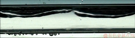
Figure 4 Flow image of swirl stratified flow (8#, Vg=1.34 m/s, Vl=1.47 m/s)
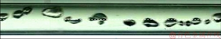
Figure 5 Flow image of swirl bubble flow (5#, Vg=0.20 m/s, Vl=1.87 m/s)

Figure 6 Flow image of swirl slug flow (5#, Vg=0.81 m/s, Vl=0.59 m/s)
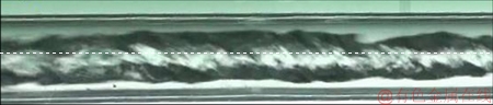
Figure 7 Flow image of swirl annular flow (5#, Vg=1.67 m/s, Vl =2.14 m/s)

Figure 8 Flow image of swirl dispersed flow (5#, Vg=3.34 m/s, Vl=2.68 m/s)
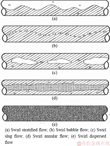
Figure 9 Schematic diagram of typical flow pattern:
Figure 10 shows the classic Mandhane flow pattern map, where Usl is the liquid phase conversion velocity and Usg is the gas phase conversion velocity. Figure 11 shows a flow pattern map of gas-liquid two-phase swirl flow generated by the vane in a horizontal pipe based on a large amount of experimental data. The straight line or curve in the figure shows the dividing line between different flow patterns. The flow pattern of gas-liquid two-phase flow is various and the boundaries are not very clear. Flow pattern is difficult to distinguish clearly. However, when dealing with two-phase hydrodynamics problems, it can be divided into several types of flow patterns under certain accuracy requirements. The hydrodynamic characteristics of each type of flow pattern are basically the same. There are currently two classification methods for flow patterns. The first classification method includes: bubble flow, slug flow, stratified flow, wavy flow, bullet flow, annular flow, and dispersed flow. The second classification method includes: dispersion flow, separated flow, and intermittent flow. The first classification method is based on the shape of the two-phase medium distribution. The second classification method is divided according to the flow mathematical model.
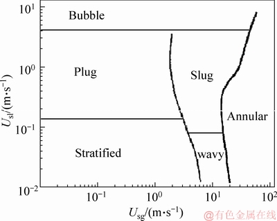
Figure 10 Mandhane flow pattern map in horizontal pipe [39]
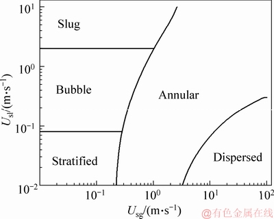
Figure 11 Swirl flow pattern map in horizontal pipe
The different flow patterns transition is difficult to determine by visual methods, and the transition of different flow patterns is not abrupt but a gradual process. In the flow pattern, there is no difference on both sides of the boundary, in other words, the transition boundary of different flow patterns is a transitional area. In general, the flow patterns are divided into two major categories: separated flow and dispersion flow. The separated flow mainly included stratified flow and annular flow. The dispersion flow mainly includes bubble flow, slug flow, and dispersed flow. Swirl stratified flow generally appears when gas and liquid phase superficial velocities are not too large. The gas phase flows in the upper part of the pipe, while the liquid phase moves forward in the lower part of the pipe. Compared with ordinary stratified flow, the gas-liquid interface has greater volatility due to the vane��s rotation. When the liquid phase velocity is basically unchanged and the gas phase velocity increases, a swirl annular flow occurs. There is still a more obvious gas-liquid interface between the gas and liquid phase. The gas phase moves forward in the shape of a columnar. The liquid phase is distributed in the form of a liquid film on the inner wall of the pipe as a result of the existence of centrifugal force. There are obvious gas-liquid interfaces, and less mixing between the gas and liquid phases. The pressure drop is researched with the spilt-phase better. Swirl bubble flow appears when the gas phase velocity is relatively small. The gas phase moved forward with tiny bubbles and the bubbles disperse in the liquid phase. When the gas phase velocity increases, the bubble is blocked and collided by the lower velocity liquid phase. After the bubbles successively collide, they become tiny bubbles that randomly disperse in the liquid phase. At this time, the flow pattern is swirl dispersed flow. In the above two flow patterns, gas phase and liquid phase are more mixed and the gas phase dispersibility is better, and it is considered to adopt a homogeneous form for research.
A flow pattern map of a gas-liquid two-phase swirl flow in a horizontal pipe is shown in Figure 11. The flow pattern map is summarized based on a large amount of data in the experiment. Compared with the classic Mandhane flow pattern, it is found:
1) Stratified flow, bubble flow and annular flow appear in the no-swirl flow and swirl flow. Plug flow appears in no-swirl flow. Plug flow does not appear in the gas-liquid two-phase swirl flow, and swirl dispersed flow appears instead.
2) Plug flow is a common flow pattern. The gas-liquid two phases move forward, which can easily cause the pipe vibration. The plug flow does not occur in the gas-liquid two-phase swirl flow. The authors believe that the gas-liquid two phases moved in the axial direction because of the swirler, and there is also a tangential movement along the cross-section, and then centrifugal force forms in the pipe. Because the liquid density is larger than the gas phase density, the liquid is gradually thrown to the inner wall of the pipe. In addition, the gas phase would also weaken the gas-liquid interface wave while moving inside the pipe because of tangential velocity, so the liquid phase does not block the pipe, and plug flow does not appear. The plug flow can easily cause pipe vibration. Therefore, the swirl flow can improve the flow stability.
3) The annular flow appears in both no-swirl and swirl flow. However, the boundary of the annular flow is not the same in the two working conditions. For ordinary no-swirl flow, annular flow generally appears when the gas flow is larger than 20 m/s, but for gas-liquid swirl flow, according to experimental observations, the gas flow velocity range of the swirl annular flow is from 0.23 to 3.3 m/s. The scope is obviously different. The authors believe that the centrifugal force generated by the tangential flow rate was an important reason. Due to the effect of centrifugal force, the liquid phase is thrown to the inner pipe wall, the gas phase can pass through the liquid phase to form a gas column at a lower flow, and an annular flow appears. However, the gas-liquid interface is unstable when the gas flow velocity is more than 3.3 m/s. The liquid phase is dispersed by the gas phase and then the dispersed flow appears.
4) Swirl dispersed flow appears where the gas superficial velocity is slightly high, and the gas flows in the pipe with liquid dropt at a relatively high velocity, and the gas phase is evenly dispersed in the liquid in the form of extremely fine bubbles or micro bubbles. When the gas flow velocity accelerates, the gas-liquid two phases become dispersive. Therefore, the gas-liquid mixing degree of swirl dispersed flow is the highest in the all flow patterns. So pressure drop calculation of swirl dispersed flow can use the homogeneous-phase model.
3.2 Pressure drop
The pressure drop calculation of gas-liquid two-phase flow is very important in practical engineering applications. It is one of the most important topics in the research field of two-phase flow. It is also an important basis for determining the flow system pump and related power equipment during design and operation of gas-liquid two-phase flow devices. At present, many scholars have studied the two-phase frictional characteristics of the gas-liquid two-phase swirl flow in the helical pipe, accumulated certain experimental data, and also published some calculation relations. But study on the gas-liquid two-phase swirl flow gas liquid in the horizontal pipe is still lacking, and it is still a hotspot and difficulty in current research.
3.2.1 Pressure drop comparison between no-swirl flow and swirl flow
The characteristics of the pressure drop in the pure liquid phase swirl flow and the characteristics of two-phase no-swirl pressure drop are the basis and prerequisite for the research on the pressure drop characteristics of the gas-liquid two-phase swirl flow. According to relevant research results, the pressure drop per unit length in the pure liquid phase swirl flow pipe is the smallest. Because in the pure liquid phase flow, the fluid disturbance is relatively small, the pressure drop is mainly composed of frictional pressure drop, and the frictional coefficient is basically constant, and the numerical value is relatively small, so the pressure drop per unit length of the pure liquid is minimal. At present, there was no relevant literature to report the pressure drop comparative data of gas-liquid two-phase no-swirl flow and gas-liquid two-phase swirl flow. As shown in Figure 12, under the same conditions, the pressure drop of the gas-liquid two-phase swirl flow further increases compared to the two-phase no-swirl gas-liquid flow, and the pressure drop gradient of the swirl flow increases with the increase of the gas-phase superficial velocity. The authors believe that whether no-swirl and swirl flow, due to the addition of gas phase, not only there is a force between the fluid and the wall of the pipe, but also there is a force between the two phases interface. From the energy balance, there are energy exchanges between the gas-liquid two-phase flows at the overall interface, and energy exchange causes the mechanical energy loss. The gas-liquid two-phase swirl flow is different from the general multi-phase flow. A tangential flow velocity would appear formed by the swirler. Therefore, centrifugal force appears in the gas-liquid two-phase swirl flow, which makes the force between the gas-liquid two-phases and the wall become stronger. In addition, the forces between the two phases would become more complex, and energy exchange between the two phases enhanced, and pressure drop is further incased.

Figure 12 Comparison of no-swirl flow and swirl flow (Vl=1.0 m/s)
3.2.2 Influence of flow velocity on pressure drop
The fluid velocity is an important factor affecting the pipe friction. In order to analyze the influence of flow velocity on pressure drop, the experimental data of 5# vane is used as the comparison object to analyze the pressure drop variation characteristics. As shown in Figure 13, in general, the pressure drop gradually increases when the gas phase flow velocity increases. The liquid- phase flow velocity also has a great influence on the pressure drop. With the increase of the liquid-phase flow velocity, the pressure drop in the pipeline also gradually increases.
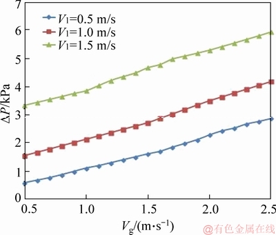
Figure 13 Influence of gas phase velocity on pressure drop (5# vane)
3.2.3 Influence of vane parameters on pressure drop
The influence of different vane swirl angles on flow pressure drop is shown in Figure 14. The vanes of 4#, 5# and 6# have the same area, and the vane swirl angle gradually increases, and the liquid flow velocity Vl is 1.0 m/s. The pressure drop gradually increases when the swirl angle increases. When the gas-liquid two-phase fluid flows, the total pressure drop includes frictional pressure drop, local frictional pressure drop, gravitational pressure drop, and accelerating pressure drop. In this experiment, there is no gravitational pressure drop and local frictional pressure drop, so the other two kinds of pressure drop are mainly considered. For the frictional pressure drop, the main influencing factors are: pressure, quality, diameter, mass flow velocity, flow direction and roughness of pipe wall. The influence of the swirl angle change on the flow pressure drop is flow direction. When the swirl angle becomes larger, the tangential velocity is larger, and the increase of the tangential velocity would affect the friction of the pipe wall and increase the pressure drop. For accelerating pressure drop, when flow pattern is the swirl bubble flow and the swirl dispersed flow, the influence is generally negligible. In summary, when the vane swirl angle increases, the pressure drop of the gas-liquid two-phase swirl flow increases.
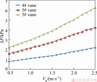
Figure 14 Influence of swirl angle on pressure drop (Vl=1.0 m/s)
The influence of different vane area on flow pressure drop is shown in Figure 15. The vanes of 2#, 5# and 8# are the same swirl angle, the vane area gradually decreases, and the liquid flow velocity Vl is 1.0m/s. When vane area decreases, the pressure drop decreases. As in the previous analysis, the total pressure drop included frictional pressure drop, local frictional pressure drop, gravitational pressure drop, and accelerating pressure drop. In this experiment, there is no gravitational pressure drop and local frictional pressure drop, so the frictional pressure drop is mainly considered. In general, when the vane area decreases, the flow pressure drop decreases.
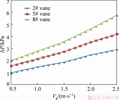
Figure 15 Influence of vane area on pressure drop (Vl=1.0 m/s)
However, the change rate of the pressure gradient is less than the change rate of vane angle.
4 Pressure drop model
The total pressure drop of the gas-liquid two-phase flow includes frictional pressure drop, gravitational pressure drop, and accelerating pressure drop. And the pressure drop of the gas-liquid two-phase swirl flow is the same as the former. For the experimental conditions in this paper, the gravitational pressure drop and the accelerating pressure drop have a small influence on the total pressure drop, and there is little effect on the final treatment results. Therefore, frictional pressure drop is the main influence on the friction loss of the gas-liquid two-phase swirl flow. For the frictional pressure drop, scholars have studied a lot, but the two-phase frictional relations obtained by different scholars are different applications, and the difference between them is often very high. The reason is the complexity of the two-phase flow problem itself. There is no way to sum up the relevant experimental results and theoretical analysis and to summarize a theory. There is no relational model that can accurately couple all the influencing factors together. It is the same for the gas-liquid two-phase swirl flow.
At present, the research on the frictional characteristics of the gas-liquid two-phase flow in the pipe under steady-state conditions includes the separate phase idea and the homogeneous phase idea. In this experiment, the flow patterns appearing in the gas-liquid two-phase swirl flow included swirl bubble flow, swirl annular flow, swirl stratified flow, swirl annular flow, and swirl dispersed flow. According to the flow characteristics of the dispersed flow and the separate flow, the pressure drop characteristics of the dispersed flow and the separate flow are studied based on the homogeneous phase model and the separate phase model respectively.
4.1 Reynolds number of gas-liquid two-phase swirl flow
In order to analyze the influence of swirl number on the frictional pressure drop, the swirl Reynolds number of liquid phase, the swirl Reynolds number of gas phase and the gas-liquid mixed swirl Reynolds number are defined.
The swirl liquid Reynolds number,
 (1)
(1)
where Vl is the average velocity of liquid phase, m/s; vl is the liquid kinematic viscosity, m2/s.
The swirl Reynolds number of gas phase,
 (2)
(2)
where Vq is the average flow velocity of gas phase, m/s; vq is the gas kinematic viscosity, m2/s.
The Reynolds number of gas-liquid two-phase swirl flow,
 (3)
(3)
where �� is the gas-liquid mixed density, kg/m3; �� is the gas-liquid two-phase mixed dynamic viscosity, Pa��s; v is the average velocity of gas-liquid two-phase, and v=Q/A, where A is section area of pipe, m2.
The formula for calculating �� of the gas-liquid two-phase mixed dynamic viscosity is as follows:
 (4)
(4)
where �� is the volumetric void fraction;
 (5)
(5)
where Ql is the liquid flow, m3/s; Qg is the gas flow, m3/s.
For the density of gas-liquid two-phase mixtures ��,
 (6)
(6)
4.2 Swirl number
At present, the swirl number of the single phase swirl flow is defined as the dimensionless swirl number, and its formula is:
 (7)
(7)
where R is the inner diameter of pipes; �� is the fluid density; u is the axial velocity; w is the tangential velocity; A is the pipe cross section area, turbulence (pulsation) can be ignored, so the velocity is considered to be the time averaged velocity.
LIU et al [40] defined the formula for the swirl number Sgl of the gas-liquid two-phase flow as follows:
 (8)
(8)
where Rg is the radius of the gas column; ��g is the gas phase density; ug is the axial velocity of gas phase; wg is the tangential velocity of the gas phase. In the same way, ��l is the liquid phase density; ul is the axial velocity of liquid phase; wl is the tangential velocity of the liquid phase; r is radial coordinate.
Finally, it can be obtained by simplification:
 (9)
(9)
where Sl is the swirl number of the liquid phase; Sg is the swirl number of the gas phase; �� is the section void fraction.
4.3 Homogeneous-phase model
Homogeneous flow model is called homogeneous-phase model. The gas-liquid two- phase mixture is regarded as a homogeneous medium. The physical parameters are the average value of two-phase medium parameters. The two- phase pressure drop is treated as a single phase medium. In this experiment, the swirl bubble flow and the swirl dispersed flow are evenly distributed in the liquid phase by the bubbles or small bubbles. They are considered single-phase media. Therefore, pressure drop of the two flow patterns is based on the homogeneous phase model.
4.3.1 Model establishment
The homogenous idea of the two-phase flow frictional characteristic is that the two-phase is regarded as an imaginary fluid, and its physical characteristics are determined by the average values of the two components of the gas phase and the liquid phase. Based on the homogenous idea, the predictive relation of two-phase flow frictional pressure drop is similar to single phase. Different scholars have given different calculation forms on the determination of physical characteristics. The calculation process for calculating the frictional pressure drop of a two-phase swirl flow using the homogeneous idea is as follows:
Darcy��s law is applied to calculating the frictional pressure gradient  as:
as:
 (10)
(10)
where ��Ps is gas-liquid two-phase total pressure drop, Pa; ��L is the calculated length, m; ��s is the on-way resistance coefficient of gas-liquid two- phase swirl flow; v is the average velocity of gas- liquid two phase, m/s; �� is the gas-liquid mixture density, kg/m3.
For the on-way resistance coefficient of the gas-liquid two-phase swirl flow ��s, it is given as:
 (11)
(11)
where �� is the friction coefficient of no-swirl flow; m or n is the coefficient or index determined according to the experimental data.
According to the experimental data of the typical flow pattern, the indexes are obtained by the regression method; m=1.16, n=0.78.
So, the on-way resistance coefficient of gas- liquid two-phase swirl flow ��s is given as:
 (12)
(12)
According to the range of experimental conditions, when the flow is laminar, it is obtained:
 (13)
(13)
when the flow is turbulent, the Blasius equation is used as:

To sum up, the homogeneous phase calculation model of gas-liquid two-phase swirl flow pressure drop is:

 (14)
(14)
In particular, when there is no swirler in the pipe, the swirl number is zero everywhere in the pipe; the fluid in the pipe is an ordinary no-swirl flow. It can be seen from Eq. (14) that the friction coefficient of gas-liquid two-phase swirl flow ��s=��, the pressure drop calculation Eq. (14) is according to Darcy��s law. It can be seen that the no-swirl pipeline resistance is included in Eq. (14), which is only a special case of swirl number Sgl=0.
4.3.2 Validation of estimated pressure drop
The homogeneous model is mainly applied to the dispersed flow. In this experiment, the object of study includes swirl bubble flow and swirl dispersed flow. The difference in the appearance conditions of the two flow patterns is mainly the gas phase velocity. Generally, when the gas flow velocity is small, swirl bubble flow appeared. When the flow velocity is large, swirl dispersed flow appears. According to the experimental data, the established homogeneous model calculation method is verified. The verification result is shown in Figure 16, where ��Ps,cal is the model calculated value and ��Ps,exp is the experimentally measured value. From the figure, we can find that the error between the model calculated value and the experimental measured value is basically within 10% for the swirl bubble flow. For the swirl dispersed flow, the error between the model calculated value and the experimental measured value is basically no more than 20%.
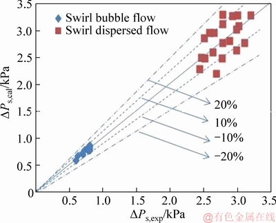
Figure 16 Comparison between experimental and estimated pressure drops (5# vane) according to Eq. (15)
4.4 Split-phase model
For the apparent interface flow such as annular flow and stratified flow, the flow model proposed by LOCKHART et al [15] and CHISHOLM [17] is applied to prediction and calculation.
4.4.1 Model establishment
LOCKHART et al [15] first put forward the general pressure drop law of two-phase flow in horizontal pipe. In experiments, air and water are used. The experimental conditions are that pipe diameter is 1.49-25.8 mm, and the length of the pipeline is 0.67-15.2 m, and the temperature is 15-30 ��C. The Lockhart and Martinelli methods were the better ones in the early calculation methods.
The split liquid phase conversion factor  and the split gas phase conversion factor
 are parameters of the two-phase frictional pressure drop proposed by LOCKHART et al [15]. They studied the two-phase flow composed of air and benzene, kerosene, water and other forms of oil. LOCKHART et al [15] defined the split liquid phase conversion factor and the split gas phase conversion factor as a function of MARTINELLI parameter X as:
 (15)
(15)
 (16)
(16)
where X2 is the Lockhart-Martinelli parameter,  ��Pl is all liquid phase swirl flow frictional pressure drop, Pa; ��Pq is all gas phase swirl flow frictional pressure drop, Pa.
The pressure drop calculation formula of the gas-liquid two-phase swirl flow is as follows:
 (17)
(17)
where ��Pql is the pressure drop of the gas-liquid two-phase swirl flow; ��Pl is all liquid phase swirl flow frictional pressure drop;  is the two-phase flow friction multiplier.
CHISHOLM [16] obtained the experimental data plot of the split liquid phase conversion coefficient in the calculation formula, and the coefficient C would be got according to the experimental conditions, which made the application of this relation in engineering more easily. At this time, the calculation formula is the Chisholm C relation. Many proposing and improvement of the relations of the two-phase frictional pressure drop are based on the Chisholm C relation. Through experimental studies, CHISHOLM [16] divided the gas-liquid components into four categories based on different laminar-turbulent combinations, taking C values of 5, 10, 12 and 20 respectively for engineering applications.
However, some scholars found that the relevant parameter C given by Chisholm did not fully reflect the actual situation [21-23]. The experimental results also indicate that the relevant parameter C is not appropriate, when it is a fixed value. The parameter C should be calculated according to the variation of the gas-liquid two- phase flow rate and other factors.
Comparing the experimental data of different pipe diameters, it is found that under the same conditions, the liquid phase friction multiplier increases when the pipe diameter decreases. Therefore, the C value must be corrected based on the experimental results. In the Chisholm relation, the coefficient C reflects the interaction of the gas- liquid interface, and the influence of mass flow, pipe diameter and other factors are not considered, especially swirl number. The swirl number should also be considered in the relation of two-phase frictional pressure drop.
Therefore, the parameter C is redefined based on the above analysis, and the influence of the gas- liquid mixing Reynolds number, volumetric void fraction, swirling number and other factors is considered. The specific form is as follows:
 (18)
(18)
The final representation of parameter C is as follows:
 (19)
(19)
where a, b, d, g and h are coefficients or indexes determined based on experimental data.
According to the experimental data of the typical flow pattern, the expression of parameter C is obtained, and index and parameter are a=6.23, b=1.05, d=1850, g=0.85 and h=0.13.
Therefore, the gas-liquid two-phase swirl flow pressure drop model considering swirl number and other factors is:
 (20)
(20)
 (21)
(21)
 (22)
(22)
Substituting Eq. (22) into Eq. (21), the two-phase flow friction multiplier can be found, and the pressure drop of the gas-liquid two-phase swirl flow can be obtained from Eq. (20).
4.4.2 Validation of estimated pressure drop
As shown in Figure 17, the influence of swirl number, volumetric void fraction and other factors establishment on the Lockhart-Martinelli correlation prediction are considered. And the flow pressure drop of the gas-liquid two-phase swirl flow in the pipe and the computed results are compared. The individual experiment error is large; most errors of the theoretical and experimental values do not exceed 10%, showing that the establishment of the equation has achieved a good pressure drop prediction effect.
4.5 Model summary
The pressure drop calculation of gas-liquid two-phase flow is hot and difficult in the study. Many scholars have concluded a two-phase pressure drop calculation model based on their own experiments or analysis of a large number of existing data, but the research on the pressure drop of gas-liquid two-phase swirl flow is relatively less. The pressure drop characteristics of gas-liquid two-phase swirl flow are studied according to two kinds of flow patterns: dispersed flow and separate flow. A homogeneous pressure drop model and a split-phase pressure drop model are established. The authors believe that the boundary of the flow pattern is a fairly wide transition zone, when the pressure drop is studied in the transition zone, the formula corresponding to the flow pattern on both sides should be selected for calculation, so that the closest calculation model can be selected. In general, the homogeneous pressure drop model is applicable to swirl bubble flow and swirl dispersed flow with an error within 20%. The split-phase pressure drop model is applicable to swirl annular flow and swirl stratified flow with an error within 10%. Both models have good engineering application prospects.

Figure 17 Comparison between experimental and estimated pressure drops (5# vane), according to Eq. (22):
5 Conclusions
An experimental study on the frictional pressure drop characteristics of gas-liquid two- phase swirl flow with vane is carried out. The research results are as follows.
1) The flow pattern of the gas-liquid two-phase swirl flow in the horizontal pipe is divided into five types: swirl stratified flow, swirl bubble flow, swirl slug flow, swirl annular flow and swirl dispersed flow. According to the gas-liquid two-phase distribution and the interface characteristics, all flow patterns are divided into two types: separated flow and dispersion flow. The separated flow includes swirl annular flow and swirl stratified flow. The dispersion flow mainly includes swirl dispersed flow and swirl bubble flow.
2) A gas-liquid two-phase swirl flow pattern map is drawn according to the experimental data, which is compared with the classic Mandhane flow pattern map. The dispersed flow can increase the gas-liquid two-phase contact area greatly. However, slug flow does not occur, slug flow easily causes the pipe vibration; therefore, the swirl flow can improve the flow stability. The boundary of the annular flow moved. For no-swirl flow, the Mandhane flow pattern map shows that the annular flow generally occurs when the gas-phase flow velocity is larger than 20m/s. For the swirl flow, the annular flow occurs when the gas-phase flow velocity is from 0.23 to 3.3 m/s.
3) The flow velocity is an important factor affecting the pressure drop. The pressure drop in the pipe increases with the increase of the gas phase superficial velocity. Vane parameters have a great influence on pressure drop. With the increase of the swirl angle or the reduction of vane area, the flow pressure drop gradually increases. Compared with gas-liquid two-phase no-swirl flow, the pressure drop of gas-liquid two-phase swirl flow is larger than no-swirl flow. With the increase of gas-phase superficial velocity, the pressure drop gradient of swirl flow is higher than no-swirl flow.
4) According to the two kinds of flow patterns, the homogeneous pressure drop model and the split-phase pressure drop model are established. For the homogeneous pressure drop model, the overall error rate of the frictional pressure drop of the gas-liquid two-phase swirl flow is no more than 20%. For the split-phase pressure drop model, the calculated values are in good agreement with the experimental values, and most predictions are within ��10% of the experimental value. In general, the two models have better prediction effects on swirl bubble flow, swirl dispersed flow, swirl annular flow, and swirl stratified flow. The prediction error range is not more than 20%, which has a good prospect of engineering application.
References
[1] MANGLIK R. Swirl flow heat transfer and pressure drop with twisted-tape inserts [J]. Adv Heat Transfer, 2004, 36: 183-265.
[2] GUO Lie-jin. Two phase multiphase flow mechanics[M]. Xi��an, China: Xi��an Jiaotong University Press, 2002. (in Chinese)
[3] CHEN Xue-jun, CHEN Li-xun. Gas-liquid two-phase flow and heat transfer basis [M]. Beijing, China: Science Press, 1995. (in Chinese)
[4] BAKER O. Simulations flow of oil and gas [J]. Oil and Gas Journal, 1954, 26: 185-190.
[5] MANDHANE J, GREGORY G, AZIZ K. A flow pattern map for gas-liquid flow in horizontal pipes [J]. International Journal of Multiphase Flow, 1974, 1: 537-553.
[6] TAITEL Y, DUKLER A. A model for predicting flow regime transitions in horizontal and near horizontal gas liquid flow [J]. AIChE Journal A, 1976, 22(1): 47-55.
[7] WEISMAN J. The effect of fluid properties and pipe diameter on two-phase flow patterns in horizontal lines [J]. International Journal of Multiphase Flow, 1979, 5(6): 437-462.
[8] HEWITT G F, ROBERTS D. Studies of two-phase flow patterns by simultaneous X-ray and flash photography [R]. UKAEA Report AERE-M2159. 1969.
[9] WEISMAN J, KANG S. Flow pattern transitions in vertical and upwardly inclined lines [J]. International Journal of Multiphase Flow, 1981, 7: 271-291.
[10] BARNEA D, SHOHAM O, TAITEL Y. Flow pattern transition for gas-liquid flow in horizontal and inclined pipes: Comparison of experimental date with theory [J]. International Journal of Multiphase Flow, 1980, 6(3): 217-225.
[11] BARNEA D, SHOHAM O, TAITEL Y. Flow pattern transitions for down-ward inclined two-phase flow: Horizontal to vertical [J]. Chemical Engineering Science B, 1982, 37: 735-740.
[12] BARNEA D, SHOHAM O, TAITEL Y. Gas-liquid flow in inclined tubes: flow pattern transitions for upward flow [J]. Chemical Engineering Science, 1985, 40(1): 131-136.
[13] BARNEA D. A unified model for predicting flow pattern transition for whole ranges of pipe inclinations [J]. International Journal of Multiphase Flow, 1987, 13(1): 1-12.
[14] CHEN Jia-lang. Oil gas & liquid two phase flow [M]. Beijing, China: Petroleum Industry Press, 2007. (in Chinese)
[15] LOCKHART R, MARTINELLI R C. Proposed correlation of data for isothermal two-phase two-component flow in pipes [J]. Chem Eng Progress, 1949, 45(1): 39-48.
[16] CHISHOLM D. Pressure gradients due to friction during the flow of evaporating two-phase mixtures in smooth tubes and channels [J]. International Journal of Heat and Mass Transfer, 1973, 16(2): 347-358.
[17] CHISHOLM D. A theoretical basis for the Lockhart- Martinelli correlation for two-phase flow [J]. Int J Heat Mass, 1967, 10: 1767-1778.
[18] CHEN Xue-jun. Multiphase flow physics [M]. Xi��an, China: Xi��an Jiaotong University Press, 2005. (in Chinese)
[19] KREITH F, SONJU O. The decay of a turbulent swirl in a pipe [J]. J Fluid Mech, 1965, 22: 257-271.
[20] SENO Y, NAGATA T. Swirl flow in long pipes with different roughness [J]. Bulletin of JSME, 1972, 15: 1514-1521.
[21] FACCIOLO L, TILLMARK N, TALAMELLI A. A study of swirling turbulent pipe and jet flows [J]. Phys Fluids 2007, 19: 35105-1-35105-18.
[22] HORRI K, MATASUMAE Y, CHENG X. A study of swirl flow (part3), opening and orientation contral of fiber by swirl flow [J]. Trans Japan Soc Aero Space Sci, 1990, 32(8): 893-899.
[23] KANIZAWA F, RIBATSKI G. Two-phase flow patterns and frictional pressure drop inside tubes containing twisted-tape inserts [C]// The 6th International Conference on Transport Phenomena in Multiphase Systems. Poland. 2011.
[24] KANIZAWA F, HERNANDES R, MORAES A, RIBATSKI G. A new correlation for single and two-phase flow pressure drop in round tubes with twisted-tapeinserts [J]. J Brazilian Soc Mech Sci Eng, 2011, 33: 243-250.
[25] JESUS M, JOHN R. Flow pattern based two-phase frictional pressure drop model for horizontal tubes, part II: New phenomenological model [J]. International Journal of Heat and Fluid Flow, 2007, 28: 1060-1072.
[26] MULLER H, HECK K. A simple frictional pressure drop correlation for two-phase flow in pipes [J]. Chem Eng Process, 1986, 20: 297-308.
[27] FABIO T, GHERHARDT R. Two-phase flow patterns and pressure drop inside horizontal tubes containing twisted-tape inserts [J]. International Journal of Multiphase Flow, 2012, 47: 50-65.
[28] SUN Xi-huan, SUN Xue-lan, ZHAO Yun-ge. Experimental research on the local generator and the outlet velocity distribution of swirl flow in circular pipe [J]. Journal of Taiyuan University of Technology, 2003, 34(2): 122-125.
[29] SUN Xi-huan. Experimental research on the hydraulic characteristics and particle suspended mechanics in swirl pipe flow with horizontal axis [M]. Xi��an, China: Xi��an University of Technology, 2000.
[30] ZOHIR A, ABDEL A, HABIB M. Heat transfer characteristics in a sudden expansion pipe equipped with swirl generators [J]. International Journal of Heat and Fluid Flow, 2011, 32: 352-361.
[31] FABIO T, TAYE S, GHERHARDT R. Evaluation of the heat transfer enhancement and pressure drop penalty during flow boiling inside tubes containing twisted tape insert [J]. Applied Thermal Engineering, 2014, 70(1): 328-340.
[32] WANG Shu-li, RAO Yong-chao, WU Yu-xian. Experimental research on gas-liquid two-phase swirl flow in horizontal pipe [J]. China Petroleum Processing and Petrochemical Technology, 2012, 14(3): 24-32.
[33] WANG Shu-li, RAO Yong-chao, WEI Ming-jiao. Experimental study on the pressure drop of gas-liquid two-phase swirl flow [J]. Science Technology & Engineering, 2013, 28(1): 105-110.
[34] WANG Shu-li, RAO Yong-chao, WU Yu-xian. Experimental study on gas-liquid swirl flow generated by twist tape [J]. Chinese Journal of Hydrodynamics, 2013, 28(1): 105-110.
[35] LI Jian-min, WANG Shu-li, RAO Yong-chao. Influence of surfactant on flow characteristics of gas-liquid two phase swirl pipe flow [J]. Chinese Journal of Hydrodynamics, 2015, 30(1): 18-23.
[36] RAO Yong-chao, WANG Shu-li, ZHOU Shi-dong. Experimental research on velocity distribution and attenuation characteristic of swirl flow by LDV [J]. Journal of Fluids Engineering, 2014, 136(1): 011104-1-011104-9.
[37] SHYY W C, CAI Zong-xian. Heat transfer and pressure drop in a reciprocating blind duct with swirls generated by a lateral entry jet [J]. Experimental Thermal and Fluid Science, 2011, 35: 1067-1085.
[38] FEI Yan, AKIRA R, HIRONOBU N. An experimental study on a horizontal energy-saving pneumatic conveying system with soft fins [J]. Powder Technology, 2012, 217: 616-622.
[39] MANDHANE J. Flow pattern map for gas-liquid flow in horizontal pipe [J]. Int J Multiphase Flow, 1974, 1: 537-555.
[40] LIU Wen, BAI Bo-feng. Swirl decay in the gas�Cliquid two-phase swirling flow inside a circular straight pipe [J]. Experimental Thermal and Fluid Science, 2015, 68: 187-195.
(Edited by FANG Jing-hua)
���ĵ���
ˮƽ������Һ�����������������ͺ�ѹ��
ժҪ����Һ������������������������Һ����Ӵ�������������Һ���ȴ���Ч�ʡ����������Դٽ���Ȼ��ˮ�����γɺ�ȷ����Ȼ��ˮ���ャ���������ȫ������Ҫ��ʵ��Ӧ�ü�ֵ����ʵ��װ�����л��������Ƴɣ�ʵ�����Ϊ������ˮ�����ݸ߷ֱ������������Һ������������ԣ���ˮƽ������Һ���������������ͽ����˻��֡��о���ˮƽ������Һ����������������ͼ�������ٺ�ҶƬ������ѹ����Ӱ�졣�������������͵���Һ����������ѹ��ģ�ͣ������������ͷ���ѹ��ģ�Ͷ�������״����������ɢ����������״���������ֲ���Ԥ��Ч���Ϻã�Ԥ��������20%��
�ؼ��ʣ����������������������ͣ���������ѹ��
Foundation item: Project(51574045) supported by the National Nature Science Foundation of China
Received date: 2018-04-25; Accepted date: 2018-12-10
Corresponding author: WANG Shu-li, PhD, Professor; Tel: +86-13813698610; E-mail: wsl@cczu.edu.cn; ORCID: 0000-0003-3573- 5034
Abstract: The gas-liquid two-phase swirl flow can increase the gas-liquid two-phase contact area and enhance the heat and mass transfer efficiency between gas and liquid. The swirl flow has important practical application value for promoting gas hydrate formation and ensuring the flow safe of natural gas hydrate slurry. The experimental section was made of plexiglass pipe and the experimental medium was air and water. The flow pattern of the gas-liquid two-phase swirl flow in the horizontal pipe was divided, according to a high-definition camera and the overall characteristics of the gas-liquid interface. The flow pattern map of the gas-liquid two-phase swirl flow in a horizontal pipe was studied. The influence of the flow velocity and vane parameters on pressure drop was investigated. Two types of gas-liquid two-phase swirl flow pressure drop models was established. The homogeneous-phase and split-phase pressure drop models have good prediction on swirl bubble flow, swirl dispersed flow, swirl annular flow and swirl stratified flow, and the predictive error band is not more than 20%.
