

![]()

Trans. Nonferrous Met. Soc. China 22(2012) 467-475
Electrodeposition conditions of metallic nickel in electrolytic membrane reactor
REN Xiu-lian1, WEI Qi-feng1, LIU Zhe2, LIU Jun1
1. School of Marine Science and Technology, Harbin Institute of Technology at Weihai, Weihai 264209, China;
2. Henan Jindan Lactic Acid Technology Co. Ltd., Dancheng 477150, China
Received 23 March 2011; accepted 10 August 2011
Abstract:
The process parameters were optimized for the electrodeposition of nickel in an electrolytic membrane reactor. Nickel(II) and boric acid concentrations, pH and temperature were varied to evaluate the changes in current efficiency and specific energy consumption of nickel electrodeposition. The catholyte was aqueous nickel(II) sulfate and boric acid, and the anolyte was sulfuric acid solution. An anionic membrane separated the anolyte from the catholyte while maintained a conductive path between the two compartments. The results indicated that the cathode current efficiency increased with the increase of nickel concentration, pH and boric acid concentration, and decreased with the increase of current density and stirring rate. A maximum current efficiency of 97.15% was obtained under the optimized conditions of electrolyte composition of 40 g/L Ni and 40 g/L boric acid at temperature of 42 ��C and pH of 6 with a cathode current density of 300 A/m2.
Key words:
nickel; electrodeposition; anion-exchange membrane; electrolytic membrane reactor;
1 Introduction
Electrodeposited nickel is used in various fields such as transportation, service apparatus, petroleum and power. About 50% of the current worldwide production of nickel is derived from sulfide ores while the balance of new nickel is derived from lateritic sources [1, 2]. Primary new nickel production by means of electrorefining and electrowinning accounts for approximately 45% of the world��s output [3]. Cathode nickel can be produced from a variety of electrolytes, including chloride, sulphate and mixed chloride/sulfate. The latter is used for electrorefining matte from traditional matte-smelting operations, while the former two are acid systems used in hydrometallurgical processing and electrowinning [4-7].
The nickel electrowinning in mixed chloride-sulfate electrolyte is conducted at current density of 200-240 A/m2 and temperature of 50 ��C. Its current efficiency reaches up to 96%. In sulfate medium, the conditions are current density 220-230 A/m2 and operating temperature 65 ��C, while its current efficiency is 95%-97%. In chloride medium [8, 9], the nickel electrowinning conditions are as follows: current density of 220 A/m2, temperature of 60 ��C, and its current efficiency is 98%- 99%. There are several advantages in nickel chloride and nickel sulfate electrowinning. For nickel chloride electrowinning, the current efficiency is higher and the energy consumption is lower than those in the other two media due to its higher electrical conductivity, lower viscosity of the electrolyte, lower cathodic nickel and anodic chloride overpotential, higher solubility and higher activity coefficient [10]. Main production facilities of nickel from sulfide-chloride electrolyte use annealed nickel sulfide as anode in industrial processes [11]. In most of plants, each cathode slots into a suitable frame, over which a woven terylene bag is stretched [12]. The rich catholyte is needed to be pumped into cathodic compartment at a fixed rate and the spent anolyte is gradually discharged from the anode chamber. The control of bag permeability is more difficult. To solve these problems and simplify the electrolysis process, a convenient way is to recycle the anolyte and the catholyte respectively. For this purpose, an anion exchange membrane rather than a cation exchange membrane can be used as diaphragm due to its unique property of selective anions transportation. Ion exchange membrane has been widely used in electrolytic membrane reactors based on unique property of selective transportation of counter ions [13-17]. Therefore, the process of anodic dissolution of nickel matte and simultaneous electrodeposition of nickel in an anion exchange membrane electrolytic reactor in sulfate media was proposed. The flow chart of the novel approach to recover nickel in an anion exchange membrane electrolytic reactor is shown in Fig. 1. The purified filtrate and leachate are used as catholyte after the adjustment of concentrations of nickel and boric acid and pH. Compared with the industrial nickel electrowinning process, the major advantages of this process are as follows: simplicity, no evolution of chlorine gas, same level of catholyte and anolyte, no control of bag permeability, and comparatively low handling capacity and energy consumption.
In this study, the optimization of electrolysis parameters for nickel electrodeposition at the cathode is reported. The influences of parameters including the initial pH value of the solution, catholyte composition and current density, temperature, and stirring speed on the current efficiency of metallic nickel electrodeposition are studied.
2 Experimental
2.1 Anion-exchange membrane
The PE-203 was employed as an anion exchange membrane with polyethylene as substrate, RN+(CH3)3 as functional group, exchange capacity of (2��0.2) mmol/g (dry membrane), water content of about 35%, resistance of ��4.5 ��/cm2, thickness of about 0.3mm and selectivity of 96%, which was purchased from Shanghai Qiulong Chemical Company, Ltd. Before use, the membrane was equilibrated with sulfuric acid solution for one night and then rinsed with demineralized water.
2.2 Electrochemical membrane reactor
The electrodeposition of nickel metal was carried out in a divided cell, and the electrolytic membrane reactor was made of acryl glass in our laboratory. The system featured an electrolytic membrane reactor and an adjustable DC power supply. The cathode used was ASTM 301 stainless steel sheets with fixed dimensions, and a thin layer of lacquer was applied on one side of the cathode. The DSA (dimensionally stable anodes) was used as the anode, made of titanium plate coated with RuO2 (Shanxi Elade New Material Technology Co., Ltd., China) with an effective geometrical surface area of 80 mm �� 150 mm (effective surface area of 12000 mm2). The anode and cathode were separated by an anion exchange membrane. DC current (WYK-3020 constant current regulator, 0-20 A, 0-30 V) was applied to the reactor, and the cell voltage was recorded at regular intervals. The temperature of the electrolyte was controlled within a variation of ��1 ��C by a thermostatic control. The initial pH was adjusted with nickel carbonate and sulfuric acid, and the bath pH was measured continuously by pH meter.
2.3 Reagents and solutions
The catholyte was prepared by purifying mixed anolyte-leachate after the adjustment of nickel and boric acid concentrations and pH. Nickel carbonate and sulfate acid were used to adjust the pH and nickel concentration of the catholyte. The anolyte was a 0.5 mol/L sulfuric acid solution.
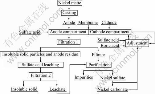
Fig. 1 Flow chart of anodic dissolution of nickel matte and simultaneous electrodeposition of nickel in anion exchange membrane reactor
2.4 Data processing
During the experimental process, samples were collected at specified time intervals. Ni electrodeposit and catholyte were analyzed by Inductively Coupled Plasma (ICP, Teledyne Leeman Labs, Prodigy XP) in order to determine the current efficiency of Ni electrodeposition as well as nickel concentrations. Standard analytical methods were employed for these measurements. From the data of the metallic nickel mass and purity, the current efficiency of the cathode was calculated. All current densities were based on the apparent surface areas of the electrodes. Current efficiency was calculated by using Eq. (1), which yield the ratio of the current effectively used for the electrodeposition of nickel to the total current supplied.
![]() (1)
(1)
where �� is the cathode current efficiency; ��Mc/��t is the mass gain of the cathode over the time interval ��t; Ac is the effective cathode area; Ic is the applied apparent current density; p is the purity of the electrodeposited metallic nickel; ENi is the electrochemical equivalent.
The specific energy consumption for the electro- deposition of nickel was calculated by
![]() (2)
(2)
where Ec is the specific energy consumption for the metallic nickel, and Vc is the cell voltage.
2.5 Electrolysis process
The cathode compartment was filled with a solution of nickel sulfate and boric acid with desired pH value, and the anode compartment contained a solution of 0.5 mol/L H2SO4. The un-lacquered face of the cathode was polished with fine silicon carbide paper and rinsed with distilled water and acetone. The anode and cathode were placed at a constant distance of 35 mm from each other and were treated together in the activated bath. The experiment was carried out under the desired temperature and constant current. During the deposition process, the catholyte was stirred with a magnetic stirrer. After the electrolysis, the cathode was removed and washed thoroughly with distilled water, and dried in an oven. The deposited plate was weighed and then scraped from the cathode surface carefully. The current efficiency was calculated according to the mass gain. The effect of the following parameters on current efficiency and power consumption was studied: concentrations of Ni2+, Na2SO4 and H3BO3, cathode current density, bath temperature and pH. All electrodeposition tests were conducted for at least 2 h in each solution.
3 Results and discussion
3.1 Effect of initial nickel concentration of catholyte
Electrolysis was conducted by varying the nickel concentration from 20 to 70 g/L in the presence of 40 g/L boric acid at temperature of 17 ��C, pH 5.2 and current density of 300 A/m2. Each anolyte contained 0.5 mol/L H2SO4 in deionized water. The distance between the anode and cathode was 35 mm. The stirring rate was 250 r/min. The results are plotted in Fig. 2 and Fig. 3. As shown in Fig. 2, the current efficiency increased from 81.88% to 90.81% steadily and significantly when the initial Ni2+ concentration in the catholyte increased from 20 to 40 g/L, and it increased slowly from 90.81% to 94.17% when the initial Ni2+ concentration increased from 40 to 70 g/L. This is obviously due to the greater availability of Ni2+ to hydrogen ions at higher Ni2+ concentrations, while the greater hydrogen evolution at lower Ni2+ concentrations results in not only lower current efficiencies but also higher power consumption.
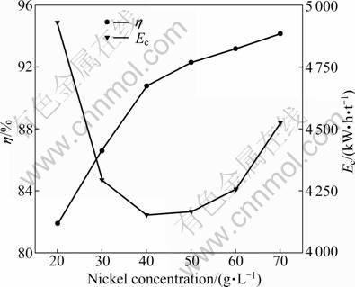
Fig. 2 Effect of Ni2+ concentration on cathode current efficiency and energy consumption
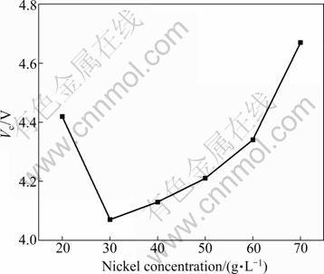
Fig. 3 Effect of Ni2+ concentration on cell voltage
Figure 3 shows that the cell voltage reaches a minimum at the nickel concentration of about 30 g/L. Since large amounts of hydrogen gas evolve on the cathode surface at lower Ni2+ concentrations, hydroxide ions (OH-) should be abundant in this region, resulting in a local pH increase of the catholyte. According to the Pourbaix diagram, the formation of insoluble Ni(OH)2 is likely to happen, which results in an increase of cell voltage. The cell voltage increases from 4.07 to 4.67 V with the increase of Ni2+ concentration from 30 to 70 g/L. This phenomenon is contributed to the increase of viscosity and the decrease of conductivity with the increase of Ni2+ concentration. The energy required to deposit nickel drops as the Ni2+ concentration increases from 20 to 40 g/L, and then it increases, as shown in Fig. 2. This is an obvious consequence of the lower voltage requirement and the increased current efficiency. Since no additional benefit was obtained beyond 40 g/L, this value was chosen as the optimum Ni2+ concentration.
3.2 Effect of cathode current density
In order to obtain the maximum current efficiency and the minimum specific energy consumption, electrolysis was conducted at varied cathode current density from 250 to 500 A/m2 in the presence of 40 g/L of boric acid at temperature of 20 ��C, pH 5.2 with 40 g/L Ni2+. The electrolysis was performed for 2 h, and the stirring rate was 250 r/min. The distance between the anode and cathode was 35 mm. The experiment results show that the cell voltage increases linearly from 3.95 to 5.48 V with the increase of current density from 250 to 500 A/m2. This increase can be attributed to the increase in both the cathodic and anodic polarizations and the transmembrane voltage. Another important reason is the formation of insoluble nickel hydroxide. Due to the markedly increase in the surface pH, the current density increases. Figure 4 shows the effect of current density on the current efficiency and specific energy consumption. The current efficiency decreases slowly from 91.96% to 86.47% when the current density increases from 250 to 400 A/m2, then it decreases rapidly from 86.47% to 77.85% with the increase of current density from 400 to 500 A/m2. The increase in cell voltage accelerates parallel H2 evolution, thus decreases nickel deposition rate. This competitive process could give a higher polarization of the cathode, even increase the cell voltage [18]. Meanwhile, with the increase of current density, the formed insoluble nickel hydroxide depresses the reduction of nickel ion greatly, which leads to the decrease in current efficiency. Based on these results, it is difficult to determine the optimal current density value. However, based on the considerations of production speed and protection of the anion membrane, a current density of 300 A/m2 seems to be relatively appropriate. This value suggests that the electrodeposition of nickel can be performed at higher current density.
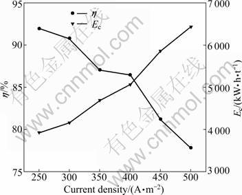
Fig. 4 Effect of current density on current efficiency and energy consumption
3.3 Effect of temperature
Deposition temperature influences the electro- chemical processes and the physical properties of electrodeposits from nickel sulfate electrolytes. Figure 5 gives the effect of temperature on cathode current efficiency and specific energy consumption at a current density of 300 A/m2, pH of 5.2, and 40 g/L electrolyte composition of Ni and boric acid, respectively. With the increase of temperature from 17 to 42 ��C, the cathode current efficiency increases from 90.81% to 94.24%, and then it decreases from 94.24% to 92.13% with the increase of temperature from 42 to 55 ��C. The higher current efficiency is due to the increased ionic mobilities at higher temperature within the range of 17 ��C and 42 ��C. When the temperature exceeds 42 ��C, the hydrolysis of Ni2+ becomes easier to form alkaline nickel salts at the interface between the deposit and the bulk solution during the process. The formation of a thicker layer of nickel hydroxide inhibits or interferes the nickel reduction. At higher temperatures the deposition process begins at lower potentials but the inhibition also occurs sooner. By considering the bearing capacity of the ion-exchange membrane, the appropriate temperature of 42 ��C was selected for the next experiments. The linear decrease of cell voltage with temperature is due to the decrease in resistances of electrolytes, anion exchange membrane, and depolarization of anodes. The decrease in cell voltage mainly leads to the drop of energy consumption.
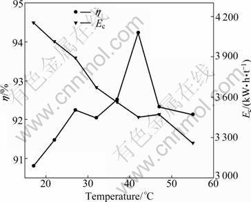
Fig. 5 Effect of temperature on current efficiency and energy consumption
3.4 Effect of stirring rate
It is recognized that forced electrolyte mixing increases the transport of H+, Ni2+ to the cathode, and decreases the thickness of double layer (��) and polarization of electrode. These effects of stirring rate will benefit current efficiency if the Ni2+ is directly reduced at the cathode. Yet, if the intermediate products form in the double layer, the increase of stirring rate will inhibit the reduction of intermediate products and thus reduce the current efficiency. To verify the effect of stirring rate on current efficiency, several stirring rates in the range of 0-550 r/min were selected to perform the experiments at current density of 300 A/m2, pH of 5.2, 40 g/L electrolyte composition of Ni and boric acid respectively, and temperature of 42 ��C. The results are plotted in Fig. 6. As shown in Fig. 6, the current efficiency decreases from 91.53% to 90.70% slightly when the stirring rate increases from 0 to 250 r/min and it decreases linearly from 90.70% to 76.97% when the stirring rate increases from 250 to 550 r/min. The decrease in current density with stirring rate indicates that the Ni2+ is not the active ion reduced at the cathode, so the active ion must be one of the intermediate products formed in the double layer. This deduction is consistent with the previously studied mechanism of nickel deposition at cathode in the acid media [19]. The reduction of intermediate products is primarily divided into two types. One is the electrocrystallization of the Ni2+ ion, which will occur in several steps. It is suggested that there are two successive faradic reactions, the first involves the formation of ![]() followed by subsequent reduction to Ni.
followed by subsequent reduction to Ni.
Ni2++e��![]() (3)
(3)
![]() +e��Ni (4)
+e��Ni (4)
In this mechanism [20, 21], the forced electrolyte mixing is insufficient to the concentration of Niads. The other one is the two one-electron transfer steps of metal reduction:
Ni2++H2O![]()
![]() +H+ (5)
+H+ (5)
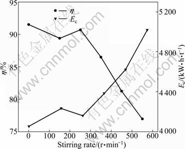
Fig. 6 Effect of stirring rate on current efficiency and energy consumption
![]()
![]()
![]() (6)
(6)
![]() +e��[Ni(OH)]ads (7)
+e��[Ni(OH)]ads (7)
[Ni(OH)]ads+H++e��Ni+H2O (8)
where Ni(OH)ads stands for the active intermediate. The evolution of H2 causes alkalization in the vicinity of the electrolyte, and the decrease in stirring rate increases the thickness of double layer. The removal of OH�C and the admission of H+ are hampered, which creates more favorable conditions for the accumulation of OH�C ions in the near-electrode layer, thus, facilitates the formation of electroactive ion ![]() [22-25]. Previous studies showed that the surface pH and �� decreased continuously with the increase of stirring rate [26]. The decrease in surface pH results in the decrease in the concentration of
[22-25]. Previous studies showed that the surface pH and �� decreased continuously with the increase of stirring rate [26]. The decrease in surface pH results in the decrease in the concentration of ![]() According to this mechanism, stirring rate can affect the current efficiency. It decreases with the increase of stirring rate. To obtain high current efficiency, the electrodeposition of nickel should be performed without the forced agitation in the electrolytic membrane reactor.
According to this mechanism, stirring rate can affect the current efficiency. It decreases with the increase of stirring rate. To obtain high current efficiency, the electrodeposition of nickel should be performed without the forced agitation in the electrolytic membrane reactor.
3.5 Effect of catholyte pH
The experiments were performed by varying pH in the range of 1.7-6.2 with current density of 300 A/m2, 40 g/L electrolyte composition of Ni and boric acid respectively, and temperature of 42 ��C. The results are plotted in Fig. 7. As shown in Fig. 7, the current efficiency increases from 48.62% to 98.15% when the bulk pH increases from 1.7 to 6.2. In the whole pH range, the electrodeposition of nickel does not proceed at 100% current efficiency. The balance of the current is consumed in hydrogen evolution [27]. The decrease of bulk pH can increase the diffusion gradient of H+ and decrease the interfacial pH, therefore, it enhances the hydrogen evolution and decreases the current efficiency. Because of the hydrogen evolution, the hydrogen ion is depleted in the electrolyte near the cathode surface. Therefore, the pH value of electrolyte near the cathode surface is always higher than that in the bulk electrolyte. The experiments show that the pH value increase results in the increase of current efficiency and this is caused by the proceeded nickel deposition through an intermediate oxyhydrate adsorbate. With the increase of the concentration of hydroxide ions at the double layer, the concentration of nickel hydroxide exceeds its solubility, a green precipitate of Ni(OH)2 is formed when the bulk pH is higher than 6.0 [27-31]. The formation of the precipitate is undesirable since it affects the quality and nature of electrodeposits. Therefore, pH of 5.2 is selected for further experiments.
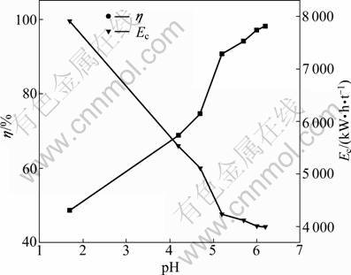
Fig. 7 Effect of initial catholyte pH on cathode current efficiency and energy consumption
One important character of anion exchange membrane is its selective permeation of anion. In the electric field, sulfate radicals transport from catholyte to anolyte through membrane. Hydrogen ions also have tendency to transport from anolyte to catholyte forced by electric field and Donnan dialysis. This tendency leads to the increase of hydrogen ion species adhering to the membrane. The diffusion of hydrogen ions from the anolyte to catholyte is accelerated by the increase of H+ concentration. The results are plotted in Fig. 8. As shown in Fig. 8, the pH of catholyte decreases with the operating time. The results also indicate that the decrease of pH can be divided into three classes. When the initial pH is below 1.7, the pH of catholyte does not vary with operating time. When the initial pH is in the range of 4.0-6.0, the catholyte pH decreases rapidly with operating time. When the initial pH is higher than 6.0, the catholyte pH decreases slowly with operating time and has higher current efficiency. This result indicates that higher pH has benefit in increasing current efficiency compared with nickel matte electrowinning. Although the formation of a strong complex between Ni2+ and H3BO3 was not found in the higher pH range (5-6), the effectiveness of the buffering action of NiSO4+H3BO3 solutions would be significant as more ![]() would form via the dissociation of H3BO3 [5]. Comparing Fig. 7 and Fig. 8, it is easy to find the interrelation between current efficiency and variation of pH. The mean current efficiency is much lower when the catholyte pH decreases rapidly. This phenomenon suggests that the catholyte pH must be adjusted continuously as shown in Fig. 1.
would form via the dissociation of H3BO3 [5]. Comparing Fig. 7 and Fig. 8, it is easy to find the interrelation between current efficiency and variation of pH. The mean current efficiency is much lower when the catholyte pH decreases rapidly. This phenomenon suggests that the catholyte pH must be adjusted continuously as shown in Fig. 1.
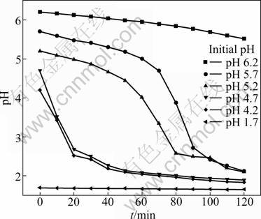
Fig. 8 Variation of pH with operation time at different initial pH
3.6 Effect of boric acid concentration
Boric acid is commonly used as a buffer to ensure high quality nickel deposition in electrolytic nickel industry, and double layer pH in the desired range can be maintained. It was confirmed that the interfacial pH is lower in the presence of boric acid [26, 27]. It was also suggested that boric acid forms a weak nickel borate complex, Ni(H2BO3)2, which acts as a homogeneous catalyst to reduce the overpotential of nickel deposition [32, 33]. To verify the effect of boric acid on current efficiency in the electrolytic membrane reactor, experiments were performed by varying boric acid in the range of 20 and 45 g/L with current density of 300 A/m2, pH of 5.2, 40 g/L Ni, and temperature of 42 ��C. The results are plotted in Fig. 9. The current efficiency increases from 84.48% to 92.99% as the initial concentration of boric acid increases from 20 to 45 g/L. The increase of current efficiency is caused by the formation of nickel borate which increases the over- potential of hydrogen and decreases the evolution of H2 [34]. The nickel borate also acts as a homogeneous catalyst to reduce the overpotential for nickel deposition. The increase of current efficiency leads to the decrease of energy consumption as shown in Fig. 9. Compared with lower boric acid concentration of 5-10 g/L in mixed chloride-sulfate electrolyte, higher concentration of boric acid seems to be the shortage in the electrolytic membrane reactor. Since the anolyte and catholyte are recycled respectively, there is no need to purify the catholyte frequently. And the concentration of boric acid in the catholyte would not decrease. Therefore, it is only necessary to add nickel sulfate into catholyte to adjust the concentration of nickel with the depletion of nickel in the electrolysis. The consumption of boric acid in the electrolytic membrane reactor would be lower compared with the industrial electrowinning.
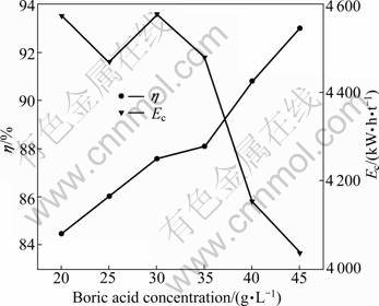
Fig. 9 Effect of boric acid concentration on cathode current efficiency and energy consumption
3.7 Effect of sodium sulfate concentration
Sodium sulfate is commonly used in mixed chloride-sulfate electrolyte to elevate the conductivity of electrolyte. The concentration of sodium sulfate used is commonly about 150 g/L. For comparison, the effect of sodium sulfate on the current efficiency and energy consumption was evaluated in the membrane electrolytic reactor. The experiments were performed by varying sodium concentration from 0 to 150 g/L in electrolyte with 40 g/L nickel and boric acid at pH 6.0 and 17 ��C. The results are plotted in Fig. 10. As shown in Fig. 10, the current efficiency decreases from 90.70% to 78.43%. With the increase of sodium sulfate concentration, sodium ions assemble in the double layer in the electric field. The aggregated sodium ions may inhibit the reduction of active nickel intermediate, which results in the decrease of current efficiency. The other important phenomenon observed in the electrolytic membrane reactor is the pH value decrease in catholyte with operation time prolonging. The results are plotted in Fig. 11. As shown in Fig. 11, pH value decreases more rapidly when the catholyte contains sodium sulfate. As discussed in section 3.5, the decrease of pH value increases the evolution of hydrogen gas. The decrease of pH may be a more important factor that leads to the decrease of the cathodic current efficiency, rather than the assembling of sodium ions in the double layer. It is well known that the selective permeation of ion exchange membrane is impossible to reach 100%. In the electrolytic anion exchange membrane reactor, the main permeating ions are sulfate radicals from cathode compartment to anode compartment in the electric field, meanwhile, hydrogen ions transport from anolyte to catholyte through anion exchange membrane forced by dialysis. The electric energy consumption is much higher when electrolyte contains sodium sulfate. This result differs greatly from that of industrial electrowinning in mixed chloride-sulfate electrolyte. It is obvious that the introduction of sodium sulfate has no benefit in improving cathodic current efficiency.
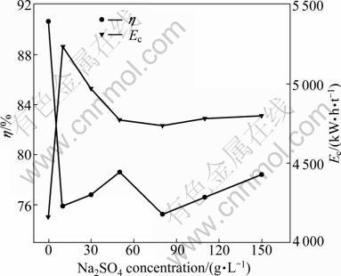
Fig. 10 Effect of Na2SO4 concentration on cathode current efficiency and energy consumption
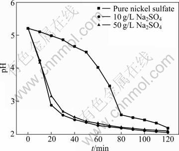
Fig. 11 Variation of pH with operation time at different concentrations of Na2SO4
4 Conclusions
1) The conditions for the deposition of nickel in the anion-exchange membrane electrolysis reactor were investigated. The results reveal that current density, boric acid concentration and pH have significant impacts on the cathodic current efficiency, while sodium sulfate concentration and agitation have negative effect on the current efficiency.
2) Compared with nickel matte electrowinning, electrodeposition of nickel in electrolytic membrane reactor can be performed at lower nickel concentration, higher boric acid concentration, pH and current density. The introduction of sodium sulfate and the elevation of agitation inhibit the reduction of nickel intermediate.
3) The optimized conditions are as follows: current density of 300 A/m2, nickel and boric acid concentration of 40 g/L respectively, pH value of 6, temperature of 42 ��C, without agitation.
Acknowledgements
The authors would like to thank WEI Lan in Ji��nan University, China, for her efforts in developing a grammatical and cohesive manuscript.
References
[1] ANTHONY M T, FLETT D S. Nickel processing technology: A review [J]. Minerals Industry International, 1997, 1: 26-42.
[2] SUDOL S. The thunder from down under: Everything you wanted to know about laterites but were afraid to ask [J]. Canadian Mining Journal, 2005, 126(5): 8-12.
[3] MOSKALYK R R, ALFANTAZI A M. Nickel sulphide smelting and electrorefining practice: A review [J]. Mineral Processing and Extractive Metallurgy Review, 2002, 23(3/4): 141-180.
[4] HOLM M, O'KEEFE T J. Electrolyte parameter effects in the electrowinning of nickel from sulfate electrolytes [J]. Minerals Engineering, 2000, 13(2): 193-204.
[5] TILAK B V, GENDRON A S, MOSOIU M A. Borate buffer equilibria in nickel refining electrolytes [J]. Journal of Applied Electrochemistry, 1977, 7(6): 495-500.
[6] MUIR D M, HO E. Process review and electrochemistry of nickel sulphides and nickel mattes in acidic sulphate and chloride media [J]. Mineral Processing and Extractive Metallurgy, 2006, 115(2): 57-65.
[7] LUPI C, PASQUALI M, DELLERA A. Studies concerning nickel electrowinning from acidic and alkaline electrolytes [J]. Minerals Engineering, 2006. 19(12): 1246-1250.
[8] PALMER C M, JOHNSON G D. The Activox? process: Growing significance in the nickel industry [J]. JOM, 2005, 57(7): 40-47.
[9] REN Hong-jiu, WANG Li-chuan. A handbook for extractive metallurgy of nonferrous metals [M]. Beijing: Metallurgical Industry Press, 2000: 664-665. (in Chinese)
[10] JI J X. Fundamental aspects of nickel electrowinning from chloride electrolytes [D]. Canada: The University of British Columbia, 1994: 15-20.
[11] MOSKALYK R R, ALFANTAZI A M. Nickel laterite processing and electrowinning practice [J]. Minerals Engineering, 2002, 15(8): 593- 605.
[12] PAVILIDES A G. Developments in cobalt and nickel electrowinning technology [EB/OL]. [2011-02-17]. http://www.batemanengineering. com/TECHNOLOGY/Technology Technical Papers/Nickel.pdf.
[13] REN X L, WEI Q F, HU S R, WEI S J. Electrochemical oxidation of Ce(III) to Ce(IV) and deposition of copper powder in an electrolytic membrane reactor [J]. Hydrometallurgy, 2010, 103(1-4): 205-210.
[14] REN X L, WEI Q F, HU S R, WEI S J. The recovery of zinc from hot galvanizing slag in an anion-exchange membrane electrolysis reactor [J]. Journal of Hazardous Materials, 2010, 181(1-3): 908-915.
[15] WEI Q F, REN X L, DU J, WEI S J, HU S R. Study of the electrodeposition conditions of metallic manganese in an electrolytic membrane reactor [J].Minerals Engineering, 2010, 23(7): 578-586.
[16] SAVARI S, SACHDEVA S, KUMAR A. Electrolysis of sodium chloride using composit poly(styrene-co-divinylbenzene) cation exchange membranes [J]. Journal Membrane Science, 2008, 310(1-2): 246-261.
[17] FAVERJON F, RAKIB M, DURAND G. Electrochemical study of a hydrogen diffusion anode-membrane assembly for membrane electrolysis [J]. Electrochimica Acta, 2005, 51(3): 386-394.
[18] RAMBLA J, BRILLAS E, CASADO J. Nickel electrowinning using a Pt catalysed hydrogen-diffusion anode. Part II: Batch tank with a sulphate bath [J]. Journal of Applied Electrochemistry, 1999, 29(10): 1211-1216.
[19] SARABY-REINTJES A, FLEISCHMANN M. Kinetics of electro- deposition of nickel from Watts baths [J]. Electrochimica Acta, 1984, 29(4): 557-566.
[20] AMBLARD J, EPELBOIN I, FROMENT M. Inhibition and nickel electrocrystallization [J]. Journal of Applied Electrochemistry, 1979, 9(2): 233-242.
[21] MATLOSZ M. Competitive adsorption effects in the electro- deposition in iron-nickel alloys [J]. Journal of the Electrochemical Society, 1993, 140(8): 2272-2279.
[22] STRE?KOV? M, ORI??KOV? R, ROZIK R, TRNKOV? L, G?LOV? M A. Study of nickel electrodeposition on paraffin- impregnated graphite electrode [J]. Helvetica Chimica Acta, 2006, 89(4): 622-634.
[23] ORINAKOVA R, STRECKOVA M, TRNKOVA L. Comparison of chloride and sulphate electrolytes in nickel electrodeposition on a paraffin impregnated graphite electrode [J]. Journal of Electroanalytical Chemistry, 2006, 594(2): 152-159.
[24] GBMEZ E, POLLINA R, VALL?S E. Morphology and structure of nickel nuclei as a function of the conditions of electrodeposition [J]. Journal of Electroanalytical Chemistry 1995, 397(1/2): 111-118.
[25] TKALENKO M D, TKALENKO D A, KUBLANNOVSKYI V S. Change in the pH of solution and the cathodic passivation of metals under the conditions of electrochemical protection in aqueous media [J]. Materials Science, 2002, 38(3): 394-398.
[26] DELIGIANNI H, ROMANKIW L T. In situ surface pH measurement during electrolysis using a rotating pH electrode [J]. IBM J Res & Dev, 1993, 37(2): 85-95.
[27] JI J, COOPER W C, DREISINGER D B, PETERS E. Surface pH measurements during nickel electrodeposition [J]. Journal of Applied Electrochemistry, 1995, 25(7): 642-650.
[28] VALL?S E, POLLINA R, G?MEZ E. Relation between the presence of inhibitors and deposit morphology in nickel deposition [J]. Journal of Applied Electrochemistry, 1993, 23(5): 508-515.
[29] NJAU K N, JANSSEN L J. Electrochemical reduction of nickel ions from dilute solutions [J]. Journal of Applied Electrochemistry, 1995, 25(10): 982-986.
[30] YIN K, LIN B T. Effects of boric acid on the electrodeposition of iron, nickel, and iron-nickel [J]. Surface and Coatings Technology, 1996, 78(1-3): 205-210.
[31] HUANG C H. Effect of surfactants on recovery of nickel from nickel plating wastewater by electrowinning [J]. Water Research, 1995, 29(8): 1821-1826.
[32] GANGASINGH D, TALBOT J B. Anomalous electrodeposition of nickel-iron [J]. Journal of the Electrochemical Society, 1991, 138(12): 3605-3611.
[33] HOARE J P. Boric acid as a catalyst in nickel plating solutions [J]. Journal of the Electrochemical Society, 1987, 134(12): 3102-3103.
[34] LU Jing, YANG Qi-hua, ZHANG Zhao. Effects of additives on nickel electrowinning from sulfate system [J]. Transactions of Nonferrous Metals Society of China, 2010, 20(s1): s97-s101.
���ӽ���Ĥ�����е����������
������1, ���1, �� ��2, �� ��1
1. ��������ҵ��ѧ(����) �����ѧ�뼼��ѧԺ������ 264209��2. ���Ͻ�����Ƽ�����˾������ 477150
ժ Ҫ�������ӽ���Ĥ�����е���������������������Ż����о���(II)������Ũ�ȡ�pH���¶ȶԵ�������ĵ���Ч�ʺ��ܺĵ�Ӱ�졣��������ҺΪ���������������Һ������ҺΪ������Һ�����������ӽ���Ĥ�����������Ҹ�����ͬʱά�ּ��Ҽ�ĵ����ԡ������������������Ч������������Ũ���Լ�pHֵ�����Ӷ���ߣ�������ܶȺͽ������ʵ���������͡��õ����Ż��������Ϊ��Ni 40 g/L������40 g/L���¶�42 oC��pH 6�����������ܶ�300 A/m2���ڸ������µĵ���Ч��Ϊ97.15%��
�ؼ��ʣ�����������������ӽ���Ĥ��Ĥ����
(Edited by YUAN Sai-qian)
Corresponding author: WEI Qi-feng; Tel: +86-631-5687691; Fax: +86-631-5687205; E-mail: weiqifeng163@163.com
DOI: 10.1016/S1003-6326(11)61200-4
Abstract: The process parameters were optimized for the electrodeposition of nickel in an electrolytic membrane reactor. Nickel(II) and boric acid concentrations, pH and temperature were varied to evaluate the changes in current efficiency and specific energy consumption of nickel electrodeposition. The catholyte was aqueous nickel(II) sulfate and boric acid, and the anolyte was sulfuric acid solution. An anionic membrane separated the anolyte from the catholyte while maintained a conductive path between the two compartments. The results indicated that the cathode current efficiency increased with the increase of nickel concentration, pH and boric acid concentration, and decreased with the increase of current density and stirring rate. A maximum current efficiency of 97.15% was obtained under the optimized conditions of electrolyte composition of 40 g/L Ni and 40 g/L boric acid at temperature of 42 ��C and pH of 6 with a cathode current density of 300 A/m2.
