

Numerical simulation of standing waves for ultrasonic purification of magnesium alloy melt
SHAO Zhi-wen(��־��), LE Qi-chi(������), CUI Jian-zhong(����), ZHANG Zhi-qiang(��־ǿ)
Key Laboratory of Electromagnetic Processing of Materials, Ministry of Education,Northeastern University, Shenyang 110004, China
Received 23 September 2009; accepted 30 January 2010
Abstract:
It was attempted to enhance and accelerate the separation of oxidation inclusions from magnesium alloy melt by virtue of ultrasonic agglomeration technology. In order to investigate the feasibility and effectiveness of standing waves for ultrasonic purification of magnesium alloy melt, numerical simulation and relevant experiment were carried out. The numerical simulation was broken into two main aspects. On one hand, the ultrasonic field propagations within the cells with various shapes were characterized by numerical solutions of the wave equation and with a careful choice of geometry a nearly idealized standing wave field was finally obtained. On the other hand, within such a standing wave field the agglomeration behavior of oxidation inclusions in magnesium alloy melt was analyzed and discussed. The agglomeration time and agglomeration position of oxidation inclusions were predicted with numerical simulation method. The results show that the oxidation inclusions whose apparent densities are close to the density of the melt can agglomerate at wave nodes in a short time which to a great extent enhances and accelerates the separation of oxidation inclusions from magnesium alloy melt.
Key words:
magnesium alloy melt; purification; standing waves; numerical simulation;
1 IntroductionOwing to its comprehensive advantages, including low density, high specific strength and stiffness, excellent machinability, superior damping and magnetic shielding capacities, magnesium alloy offers a wide range of potential applications to various fields, such as aviation and spaceflight, automobile and computer manufacturing, communication, and optic instruments[1-4]. However, during smelting or casting process, more than often, a large quantity of inclusions will be introduced in magnesium alloy melt as a result of their high tendency of oxidation and combustion at high temperature, which in fact severely undermines both its mechanical properties and corrosion resistance[5-7]. Therefore, it is of great importance to investigate how to remove these detrimental inclusions from magnesium alloy melt.
Nowadays, the fluxing processing, the traditional purification method for magnesium alloy melt, not only bears the risk of flux inclusions pollution but also faces more and more environmental challenges. Hence, more attentions have been paid to exploiting new effective ways to purify magnesium alloy melt[8-9]. For instance, the physical filtering processing which takes advantage of stainless steel mesh to separate those notorious inclusions from the magnesium alloy melt appears simple and convenient, but unfortunately it fails to get rid of those tiny oxidation inclusions from melt[10]. On the other hand, the technologies which exploit acoustic radiation forces on particles within ultrasonic standing waves, including particle separation, fractionation and agglomeration, are broadly used in areas such as biotechnology, material processing and filter systems[11-14]. In this study, ultrasound was used to treat magnesium alloy melt with the aim to enhance and accelerate the separation of oxidation inclusions from melt. Due to the fact that there are few reports concerning ultrasonic purification of magnesium alloy melt, especially studies with numerical simulation method, both numerical simulation and experimental analysis were developed in order to investigate its feasibility and effectiveness, which are also helpful forus[A1] to understand how ultrasonic purification of magnesium alloy melt works. The numerical simulation consisted of two steps. Firstly, numerical solutions of the wave equation gave the ultrasonic field propagations within the cells of various shapes and with a certain geometry selected a nearly idealized standing wave field was finally found. Secondly, within such a standing wave field the agglomeration behavior of oxidation inclusions in magnesium alloy melt was analyzed and discussed. The agglomeration time and agglomeration position of oxidation inclusions were predicted with numerical simulation method.
2 Experimental2.1 Experimental apparatus and methods
As shown in Fig.1, the experimental apparatus for ultrasonic treatment used in this study consisted of a resistant furnace, an iron crucible and a metallurgic ultrasonic system with the power ranging from 0 to 2 kW, which includes an ultrasonic generator with the frequency of (20��2) kHz, a magnetostrictive transducer, and an acoustic radiator made of mild steel. The ultrasonic was introduced into magnesium alloy melt in the iron crucible by inserting the preheated radiator under CO2+0.5%SF6 atmosphere. After ultrasonic treatment the melt was quenched in water after a certain period later. AZ31 alloy was used in this investigation. The iron crucible was built up according to the result of simulation and a schematic drawing of the cell including the meanings of geometric variables used for modeling is shown in Fig.2(a). The longitudinal section of ingot was divided into four layers from top to the bottom, called top, second, third and bottom layer respectively (Fig.2(b)). Then, the corresponding field of vision was
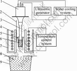
Fig.1 Schematic of experiment arrangement: 1��Ultrasonic transducer; 2��Thermocouple; 3��Ultrasonic radiator; 4��Resistance heater; 5��Iron crucible; 6��Melt; 7��Ceramic tube; 8��Water; 9��Tank
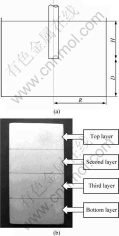
Fig.2 Schematic drawing of cell and partition method on longitudinal section of ingot: (a) Schematic drawing of cell; (b) Partition of sample
observed by Leica DMR optical microscopy and its relative area fraction of inclusion (shortened as inclusion fraction in the following passages) achieved from the measurement results of the image analysis software was used to characterize its inclusion degree.
2.2 Numerical simulation of standing waves for ultrasonic force fields
The numerical simulations can be broken into two main aspects: field modeling to predict the acoustic forces, and particle modeling to predict the effect of these forces on the particles[15-16].
2.2.1 Field modeling
In order to study the ultrasonic field propagation, numerical simulations have been carried out. As linear wave propagation has been assumed and the shear stress has been neglected, the acoustic pressure can be obtained by solving the wave equation:
![]() (1)
(1)
With the time harmonic assumption, a solution of the form was obtained:
![]() (2)
(2)
where �� is the angular frequency of the acoustic wave and given by ��=2��f. Then, the spatial variation of the acoustic pressure p(r, z) can be given by solution of the homogeneous Helmholtz equation:
![]() (3)
(3)
The intensity distribution, I(r, z), can be obtained from the equation:
![]() (4)
(4)
The homogenous Helmholtz equation (Eq.(3)) was solved by the finite element method. It should be noted that in order to obtain an accurate numerical solution of the Helmholtz equation, the discretization stepsize h should be adjusted to satisfy the following condition[17-19]:
![]() ����1 or k?h=constant (5)
����1 or k?h=constant (5)
where �� is the wavelength and k is the wave number (k=��/c). However, under this condition, the errors of the finite element solution grow sharply as the wave number k increases, which is termed as pollution effect[20-21]. To overcome this problem, an adequate refined mesh has been used just like others[22-23].
Finally, the boundary conditions are:
1) p=0 at the liquid/air interfaces corresponding to a total reflection condition as soft walls.
2) p=p0 at the sonicator horn tip.
3) ?p/?n=0 at both the side walls of the horn and all the other walls which represents hard walls.
2.2.2 Particle modeling
In order to investigate the distribution of the particles in the acoustic field, the primary forces should be discussed and the momentum equation of the moving particle has been given.
2.2.2.1 Acoustic radiation force
A standing plane wave of ultrasound spatially varying along z axis in a fluid is described by
![]() (6)
(6)
and
![]() (7)
(7)
where p is incident acoustic pressure and v is incident fluid velocity vector at z; p0 and v0 are acoustic pressure amplitude and velocity amplitude, respectively; k is the wave number (k=��/c); z is the distance from the pressure node; �� is the angular frequency; t is time; and k is the unit vector in the axial direction.
By applying the acoustic radiation force theory presented by Gor��kov[24], we can describe the time-average radiation force in terms of axial (fz) and lateral (fr) components as
![]() (8)
(8)
and
![]() (9)
(9)
where V�� is the particle volume, ![]() is the transverse gradient operator, and Eac, the acoustic energy density, is the sum of the time-averaged potential ��Epot? and kinetic energy density ��Ekin?, which can be expressed respectively as
is the transverse gradient operator, and Eac, the acoustic energy density, is the sum of the time-averaged potential ��Epot? and kinetic energy density ��Ekin?, which can be expressed respectively as
![]() (10)
(10)
and
![]() (11)
(11)
The density and compressibility acoustic contrast factor can be respectively given by
![]() (12)
(12)
and
![]() (13)
(13)
where �� is the density of the fluid, �ѡ� is the density of the particle, �� is the compressibility of the fluid, and �á� is the compressibility of the particle.
2.2.2.2.2 Fluid drag
For low particle Reynold��s number, the drag force fd on a particle is calculated by Stokes�� law, that is
![]() (14)
(14)
where �� is the viscosity of the fluid, d�� is the diameter of the particle.
3.2.2.2.3 Buoyancy
The buoyancy force on a particle, fb, opposite to the gravitational force, is determined by the relative densities of the particle and fluid and can be given by
![]() (15)
(15)
4.2.2.2.4 Momentum equation of moving particles
When diffusion, the particle and particle interactions (known as Bjerknes forces)[25] are neglected. The rate of change of particle momentum becomes equal to the sum of the ultrasonic forces fz, the fluid drag force fd, and the buoyancy force fb, that is,
![]() (16)
(16)
3 Results and discussion
3.1 Results of numerical simulation
3.1.1 Results of field modelling
According to the fact that the velocity of ultrasound in magnesium alloy melt at 700 ?C is almost 4 000 m/s[26-27], a wavelength of 150 mm was chosen for modeling which corresponds to the propagation of 20 kHz ultrasound in magnesium melt. The horn tip radius r is 10 mm and the acoustic pressure amplitude at the horn tip p0 is assumed as 1 MPa.
Fig.3 shows the calculated spatial variations in ultrasound intensity for H=25 mm, R=35 mm and D=47 mm. It can be seen that, in agreement with Ref.[28], with a certain geometry of the cell selected, higher intensity was not only found in close vicinity of the horn but also other areas, which was totally different from the traditional assumption that as the distance from the horn increases, the intensity decreases accordingly to an increasing area into which it is spread.
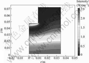
Fig.3 Spatial variations in ultrasound intensity for H=25 mm, R=35 mm and D=47 mm
The pressure amplitude distribution is simulated for different horn positions, liquid levels and cell radii. Some results of simulations are shown in Figs.4 and 5. Fig.4 presents the variation of pressure in the center of the transducer along the axial direction for different D values. The depth of immersion H and the radius of the cell R remain as 25 mm and 35 mm, respectively, whereas the radius of the horn r is 10 mm.
On the other hand, Fig.5 shows the pressure amplitude distribution of the cell for H=25 mm, R=35 mm and D=125 mm. The result shows that with a careful choice of geometry a nearly idealized standing wave field was obtained.
Keeping in mind the final use of this cell for ultrasonic agglomeration of the oxidation inclusions in
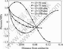
Fig.4 Pressure profile in center of transducer along axial direction for different D values while H=25 mm, R=35 mm and r=10 mm
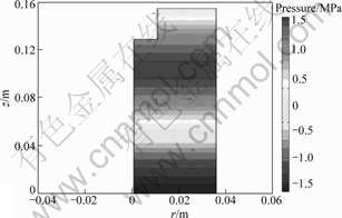
Fig.5 Pressure amplitude distribution of cell for H=25 mm, R=35 mm and D=125 mm
magnesium alloy melt, a cell with a desirable geometry H=20 mm, R=50 mm and D=130 mm is selected and used in particle modeling. Besides, the acoustic pressure amplitude at the horn tip p0 is adjusted to 2 MPa.
3.1.2 Results of particle modelling
As is known, as a result of their high tendency of oxidation and combustion at high temperature, numerous inclusions will be introduced in magnesium alloy melt during smelting or casting process. These inclusions mainly consist of magnesia (MgO) and their true density is about 2 700 kg/m3[29-31]. However, more than often, there are lots of voids unevenly distributed in the inclusions and the void ratio nearly reaches 0.65[32-33]. Consequently, the apparent density of the oxidation inclusions in the magnesium alloy melt is very close to the melt, which makes it very difficult to remove the inclusions from it. Therefore, typical values mentioned above are applied in numerical simulation and include MgO particle density ��=1 750 kg/m3 and radius R=50 ��m; magnesium alloy melt density ��=1 700 kg/m3 and dynamic viscosity ��=1.12?10-3 Pa��s[34].
Fig.6 shows the pressure amplitude distribution in conjunction with the acoustic radiation force to which MgO particles suspending in the magnesium alloy melt are subjected and Fig.7 presents the agglomeration time and position of these particles. The result indicates that within the standing wave field, particles initially located in different heights will finally agglomerate at the nodes in 90 s by virtue of acoustic radiation force.
3.2 Results of experiment
3.2.1 Effect of ultrasonic purification
Fig.8 shows the variation of the inclusion fraction of
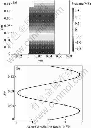
Fig.6 Pressure amplitude distribution of cell and acoustic radiation force on suspending particles: (a) Pressure amplitude distribution; (b) Acoustic radiation force
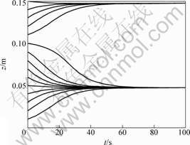
Fig.7 Agglomeration time and position of MgO particles in magnesium alloy melt
AZ31 ingots between non-ultrasonic treated and ultrasonic treated with 135 W ultrasonic power at 700 ?C for 90 s, both of which were cooled in water after being held for 30 s. It can be seen that when the ultrasound was applied, the inclusion fraction at the top layer decreases sharply from 80.6% to 3.3%, meanwhile the counterpart at the bottom layer increases from 16.5% to 86.6%. The result indicates that most inclusions suspending in the melt would ultimately sink into the bottom layer with the help of ultrasonic agglomeration, which is also predicted by the numerical simulation in above analyses.
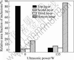
Fig.8 Effect of ultrasonic purification on inclusions of AZ31 at 700 ?C
3.2.2 Species of inclusion in AZ31 magnesium alloys
In order to validate the inclusions in the field of view exactly, the species of inclusions in AZ31 were investigated. Fig.9 presents the XRD patterns of the samples from the bottoms of AZ31 ingot after ultrasonic agglomeration. It can be seen that oxide inclusions in AZ31 mainly consist of MgO, besides ��-Mg and precipitation phases.
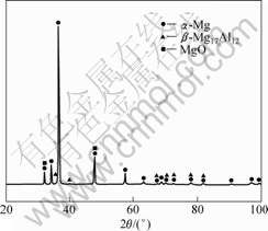
Fig.9 XRD patterns of sample from bottoms of AZ31 ingot after ultrasonic agglomeration
4 Conclusions1) The ultrasonic field propagations within the cells of various shapes could be characterized by numerical solutions of the wave equation and with a careful choice of geometry a nearly idealized standing wave field was obtained.
2) Within such a standing wave field, the agglomeration time and agglomeration position of oxidation inclusions could be predicted with numerical simulation method. The results of numerical simulation and relevant experiments indicate that the oxidation inclusions whose apparent densities are close to the melt could agglomerate at nodes in a short time which to a great extent enhance and accelerate the separation of oxidation inclusions from magnesium alloy melt.
References[1] LETZIG D, SWIOSTEK J, BOHLEN J, BEAVEN P A, KAINER K U. Wrought magnesium alloys for structural applications [J]. Material Science and Technology, 2008, 24(8): 991-996.
[2] MARK E, AIDEN B, MATTHEW B, CHRIS D, GORDON D, YVONNE D, STUART B, TIM H, PETER B. Magnesium alloy applications in automotive structures [J]. Journal of the Minerals, Metals and Materials Society, 2008, 60(11): 57-62.
[3] BETTLES C, GISON M. Current wrought magnesium alloys: Strengths and weaknesses [J]. Journal of the Minerals, Metals and Materials Society, 2005, 57(5): 46-49.
[4] MARK P S, ALEXIS M P, JEREWALA H and GEORGE D. Magnesium and its alloys as orthopedic biomaterials: A review [J]. Biomaterials, 2006, 27(9): 1728-1734.
[5] SONG G. Recent progress in corrosion and protection of magnesium alloys [J]. Advanced Engineering Materials, 2005, 7(7): 563-586.
[6] XU Si-xiang, SHU Shu-sen, MAO You-wu, WAN Li. Origination and elimination of micro-porosity in cast Mg alloy [J]. Foundry, 2007, 27(1): 11-13. (in Chinese)
[7] GAO Hong-tao, WU Guo-hua, DING Wen-jiang, ZHU Yan-ping. Purifying effect of new flux on magnesium alloy [J]. Transactions of Nonferrous Metals Society of China, 2004, 14(3): 530-535.
[8] ZHANG Jun, HE Liang-jun, LI Pei-jie. Purification technique of regenerated magnesium alloy melt [J]. Foundry, 2005, 54(7): 665-669. (in Chinese)
[9] WANG Wei, WU Guo-hua, WANG Qu-dong, DING Wen-jiang. The recent development of non-flux purification on magnesium alloy [J]. Foundry Equipment, 2007(4): 42-46.
[10] LE Q C, CUI J Z, ZHAO X H. Study on the filtering purification of magnesium alloy [J]. Special Casting & Nonferrous Alloys, 2005, 25(6): 333-334. (in Chinese)
[11] MITRI F G. Calculation of the acoustic radiation force on coated spherical shells in progressive and standing plane waves [J]. Ultrasonics, 2006, 44(3): 244-258.
[12] NEILD A, OBERTI S, DUAL J. Design, modeling and characterization of microfluidic devices for ultrasonic manipulation [J]. Sensors and Actuators B: Chemical, 2007, 121: 452-461.
[13] LAURELL T, PETERSSON F, NILSSON A. Chip integrated strategies for acoustic separation and manipulation of cells and particles [J]. Chemical Society Reviews, 2007, 36: 492-506.
[14] NEILD A, OBERTI S, DUAL J, NELSON B J. A micro-particle positioning technique combining an ultrasonic manipulator and a microgripper [J]. Journal of Micromechanics and Microengineering, 2006, 16: 1562-1570.
[15] Townsend R J, Hill M, Harris N R, White N M. Modeling of particle paths passing through an ultrasonic standing wave [J]. Ultrasonics, 2004, 42: 319-324.
[16] HARDT S, SCH?NFELD F. Microfluidic technologies for miniaturized analysis systems [M]. New York: Springer, 2007: 357-392.
[17] Ihlenburg F, Babu?ka I. Finite element solution to the Helmholtz equation with high wave number. Part I: The h-version of the FEM [J]. Comput Math Appl, 1995, 30(9): 9-37.
[18] Harari I, Hughes T J R. Finite element methods for the Helmholtz equation in an exterior domain: model problems [J]. Comput Methods Appl Mech Engrg, 1991, 87: 59-96.
[19] Babu?ka I, Ihlenburg F, Strouboulis T, Gangaraj S K. A posterior error estimation for finite element solutions of Helmholtz equation. Part I: the quality of local indicators and estimators [J]. Int J Numer Meth Eng, 1997, 40: 3443-3462.
[20] Babu?ka I, Ihlenburg F, Paik E T, Sauter S A. A generalized finite element method for solving the Helmholtz equation in two dimensions with minimal pollution [J]. Comput Math Appl, 1995, 128: 325-359.
[21] Ihlenburg F, Babu?ka I. Dispersion analysis and error estimation of Galerkin finite element methods for the Helmholtz equation [J]. Int J Numer Meth Eng, 1995, 38: 3745-3774.
[22] S��ez V, Fr��as-Ferrer A, Iniesta J, Gonz��lez-Garc��a J, Aldaz A, Riera E. Characterization of a 20 kHz sonoreactor. Part I: Analysis of mechanical effects by classical and numerical methods [J]. Ultrason Sonochem, 2005, 12: 59-65.
[23] Louisnard O, Gonzalez-Garcia J, Tudela I, Klima J, Saez V, Vargas-Hernandez Y. FEM simulation of a sono-reactor accounting for vibrations of the boundaries [J]. Ultrason Sonochem, 2008, 16: 250-259.
[24] Gor��kov L P. On the forces acting on a small particle in an acoustical field in an ideal fluid [J]. Soviet Physics Dokl, 1962, 6: 773-775.
[25] Groschl M. Ultrasonic separation of suspended particles.
[26] Blairs S. Correlation between surface tension, density, and sound velocity of liquid metals [J]. Journal of Colloid and Interface Science, 2006, 302: 312-314.
[27] McAlister S P, Crozier E D, Cochran J F. Compressibility and concentration fluctuations in liquid magnesium alloys [J]. J Phys C: Solid State Phys, 1973, 6: 2269-2278.
[28] Kl��ma J, Fr��as-Ferrer A, Gonz��lez-Garc��a J, Ludv��k J, S��ez V, Iniesta J. Optimisation of 20 kHz sonoreactor geometry on the basis of numerical simulation of local ultrasonic intensity and qualitative comparison with experimental results [J]. Ultrason Sonochem, 2007, 14: 19-28.
[29] Nadine, Pebere, Christian, Riera. Investigation of magnesium corrosion in aerated sodium sulfate solution by rlectrochemical impedance spedance spectroscopy [J]. Electrochimica Actia, 1990, 35(2): 555-561.
[30] SUN Ya-ru, LIU Zhen, WU Di. Study on chemical oxidation film of AZ91 magnesium alloy [J]. Surface Technology, 2004, 33: 43-48. (in Chinese)
[31] XUE Wen-bin, LAI Yong-chun, DENG Zhi-wei, CHEN Ru-yi, LIU Gao. The properties of coating formed by microplasma oxidation on magnesium alloy [J]. Material Science and Technology, 1997, 5: 89-92. (in Chinese)
[32] CLARK A E. Ferromagnetic materials [M]. Amsterdam: North, Holland Publishing Company, 1980: 533-534.
[33] SHEN Ze-ji, LI Bao-dong. Structure and corrosion behavior of passive films on magnesium alloys [J]. Materials for Mechanical Engineering, 2003, 27: 12-37. (in Chinese)
[34] CAO Yong-qiang. Interactions between fluxes used in the refining of Mg-Alloys and inclusions as well as the analysis on refining processing technology [D]. Jilin University, 2006.
Foundation item: Projects(2007CB613701, 2007CB613702) supported by the National Basic Research Program of China; Projects(50974037, 50904018) supported by the National Natural Science Foundation of China; Project(NCET-08-0098) supported by the Program for New Century Excellent Talents in University of China
Corresponding author: LE Qi-chi; Tel: +86-24-83683312; Fax: +86-24-83681758; E-mail: lourry@163.com
