
J. Cent. South Univ. (2017) 24: 2487-2495
DOI: https://doi.org/10.1007/s11771-017-3661-z

Strength and failure characteristics of sandstone containing two circular holes filled with two types of inclusions under uniaxial compression
DU Ming-rui(������), JING Hong-wen(������), SU Hai-jian(�պ���),
ZHU Tan-tan(��̷̷), CHEN Min-liang(������)
State Key Laboratory for Geomehanics & Deep Underground Engineering (China University of Mining and Technology), Xuzhou 221116, China
 Central South University Press and Springer-Verlag GmbH Germany, part of Springer Nature 2017
Abstract:
Plate shaped sandstones containing two fabricated circular holes that were filled with gypsum and high-strength concrete respectively were prepared for studying the effects of ligament length L ligament incline angle ��, as well as filling modes on their strength properties and failure modes. The results show that the initial cracks can be categorized as wing crack, axial tensile crack and curved tensile crack. The failure modes of ligaments can be categorized as mode of single inclined crack, mode of single axial crack and mode of two parallel cracks. The final failure modes of all specimens can be categorized as the tension-shear mixed failure and shear failure. The strength of inclusions shows little influence on the final failure modes of specimens, while the failure modes vary with L and ��. When �� is a fixed value, the peak strength ��c and elastic modulus Ec of tested specimens increase firstly with increasing L and reaches to the maximum value at L of 16 mm, then declines. When L is a fixed value, ��c declines firstly and then turns to increase as �� increases to 75�� from 45��, while Ec increases linearly. The axial stress ��p performs the similar variation trends with those of ��c versus increasing L and �� when ligaments fail.
Key words:
sandstone; two circular holes; inclusions; uniaxial compression; failure modes; strength properties��
1 Introduction
Due to the existence of non-consistent flaws, like joints, fissures, holes, and weak intercalated layers, rock mass is a medium with complicated engineering properties [1, 2]. The size, shape, and distributions of those flaws have significant influence on the failure of the rock, which has been established experimentally [3�C7], analytically [8, 9] and numerically [10, 11].
In actual rock engineering, flaws are always filled with different types of inclusions, which help to lower the risk of stress concentration and to improve the strength and deformation resistance of rock mass. Until now, studies on the mechanical properties of rock materials containing various inclusions have been conducted. ZAITSEV et al [12] proposed a model for explaining the crack propagation of a heterogeneous material containing single polygon-shaped inclusion under far field stress by using sliding crack model. TASDEMIR et al [13] studied the variations of peak strength of concrete specimens containing single filled fissure with different incline angles. ZHANG et al [14] experimentally investigated the influence of filling mode on the peak strength and plastic deformation resistance of jointed rock mass. It is shown that the peak strength and the post-peak plasticity of the jointed rock mass filled with inclusion are enhanced and the strain energy release rate decreases [14]. Owing to the differences in the mineral components, formation time and geological conditions, inclusions in rock mass show different strength properties. Now, studies on influences of different inclusions on properties of rock interest many researchers. SU et al [15] compared the effect of gypsum filling on sandstone containing single axial fissure with that of cement filling, and it is found that the damage degree of rock containing single fissure filled with cement is heavier. JANEIRO et al [16] studied the crack propagation in brittle gypsum specimens containing either one or two inclusions that are different in shapes, stiffness and strengths by performing uniaxial compression tests. However, attentions were mainly paid to the crack initiation and propagation, little discussion on the variations of peak strength was made [16]. On the other hand, other parameters like the length of ligaments between two inclusions were out of consideration [16]. YANG et al [17] pointed out that some properties of gypsum are quite different from those of real rock.Therefore, uniaxial compression tests on sandstone samples containing two circular holes filled with two types of inclusions are described here, including the specimen preparation, testing process and results. Special attentions are paid to the influences of the geometry of ligament part of specimens on the final failure modes and variations of strength properties.
2 Test preparation and procedure
2.1 Rock specimens preparation
Sandstone was selected as the tested rock as it is a typical brittle rock in the coal-measures stratum. Specimens were exploited from a coal mine located in the Southeast region in Shandong Province, China. The selected specimens are uniform in texture and the average density is around 2390 kg/m3. The main minerals of selected specimens are quartz, feldspar, and kaolinite.
The intact plate-shaped sandstone was processed to have the geometric dimension of 140 mm��70 mm��30 mm, and the end surfaces of those specimens were polished to guarantee the flatness of upper and lower sides. Two circular holes with the diameter of 8 mm were prefabricated using a high-pressure water jet cutting system, with which the substance of prepared specimens was not damaged. The ligament length L ranges from 4 mm to 20 mm in 4 mm intervals, and for a certain length, the incline angle of the ligament �� is 45��, 60�� and 75��, respectively. Sandstone specimens containing prefabricated two circular holes are shown in Fig. 1(a) and the exact distributions of hole-defects are listed in Table 1.
The prefabricated circular holes in the specimens were filled with two types of inclusions: Type I and Type II inclusion separately, in which Type I inclusion is gypsum and Type II inclusion is Sika Grout-214 non-shrink self-leveling cementation material that mainly consists of silica sand, emery, Portland cement, and water reducing agent.
The water-to-powder ratio of Type I inclusion is 0.6. The uniaxial compressive strength of hardened Type I inclusion is 25�C30 MPa, much lower than the sandstone, so it can be treated as weak filling materials in rock. Some expending agent was used to enhance the bonding strength between Type I inclusion and rock. The water-to-powder of Type II inclusion is 0.15, with which the volume expansion rate of Type II inclusion after 24 h is 0.1 and its uniaxial compressive strength is higher than 70 MPa after 28 d-curing-period at the temperature of 25 ��C, higher than sandstone according to previous experimental results [15, 17]. Type II inclusion is selected to simulate inclusions with pretty higher strength in the rock mass, such as siliceous fillings and calcium fillings.
During the filling process, the fresh mixture was grouted into circular holes firstly, and then the excess inclusion was removed from the surface of specimens, and the surface was wiped clean after about 30 min. Rock sample that has been grouted with two types of inclusions and cured for 28 d at the temperature of 25 ��C is shown in Fig. 1(b).

Fig. 1 Prepared specimens containing two circular holes:
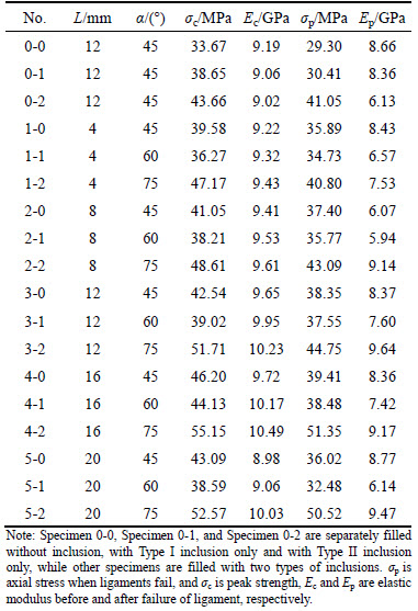
Table1 Strength and deformation parameters of tested sandstone samples
2.2 Experiment procedures
The uniaxial compression tests were conducted with an electro-hydraulic servo universal testing system, YNS-2000, in China University of Mining and Technology (Fig. 2). Before applying the load, a rigid metallic plate was placed on the top surfaces of the specimens to improve the stiffness of the system and some petroleum jelly was needed to reduce friction effect that occurred on the contact interface between samples and the metallic plates. Displacement loading method at a loading rate of 0.09 mm/min was adopted. The information of axial deformation and axial stress were collected by a computer. A Sony HDR-CX900E video camera was used to capture the process of crack propagation and two incandescent lamps were needed for providing extra lights.
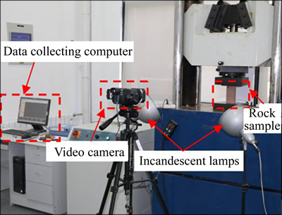
Fig. 2 Experimental facilities
3 Experimental results and analysis
3.1 Axial stress�Cstrain curves
The complete axial stress�Cstrain curves under uniaxial compression reflect many mechanical properties of rock specimens during the whole loading process [18], so the axial stress�Cstrain curves of typical specimens, as shown in Fig. 3, will be firstly discussed in this part.
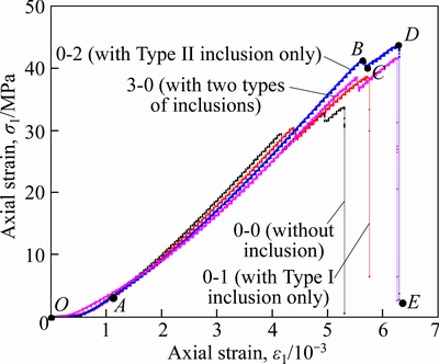
Fig. 3 Axial stress�Cstrain curves of sandstone samples containing two circular holes filled with different inclusions under uniaxial compression (L=12 mm, ��=45��)
It can be learned from Fig. 3 that the initial compaction stage which starts from point O to point A on the axial stress�Cstrain curve is obvious, which mainly results from the closure of initial micro defects in specimens under load. After that, the stiffness of tested specimens approximately remains constant and the axial stress increases linearly with increasing axial strain until reaches to point B, during which the mechanical energy in the samples accumulates. Then accompanied with the breakage of ligament region, a small amount of energy is released, and the axial stress declines to point C. After the breakage of the ligament, the axial stress increases again before reaching the peak point, i.e. point D on the curve. Then the axial stress drops sharply to almost zero, indicating that brittle failure occurs to the specimen.
Actually, the breakage of ligaments can reduce the stiffness of those specimens as Ep, the slope of stress increase path from point C to point D, is lower than Ec, i.e. the slope of stress increase path from point A to point B, and the values are shown in Table1.
3.2 Crack propagation and final failure modes
3.2.1 Categories of initial cracks
As shown in Fig. 4, the initial cracks can be categorized as three types: wing crack, axial tensile crack, and curved tensile crack. The curved tensile crack is unusual as it mainly initiates curvedly from the contact interface between Type II inclusion and rock and propagates in the rock along the axial stress direction.
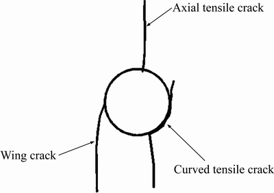
Fig. 4 Illustration of initial crack types
The stress on the contact interface between cementitious materials and rock is considered Van der Waals force [19], therefore the interfacial cementation strength is lower than the strength of hardened Type II inclusion and rock, which explains why there exists curved tensile crack.
3.2.2 Failure modes of ligament
Before the occurrence of the final failure, owing to the propagation and coalescence of initial cracks, failure of ligaments in the specimens happens, indicating the occurrence of the local failure. Failure modes of the ligament can be categorized into three types according to the distribution forms of coalesced cracks. Partial enlargement of failure modes of the ligament are shown in Fig. 5.
3.2.2.1 Failure mode of single inclined crack
Under axial load, ligament breaks when the wing cracks coalescent to the curved tensile crack. The coalescent crack distributes in the form of single incline crack with wide aperture thickness. There is an obvious trace of shear rupture along the coalescent crack and spalling of rock debris is also observed. The coalescence of crack is caused by shearing force.
3.2.2.2 Failure mode of single axial crack
This type of failure mode is caused by the coalescence of wing crack and curved tensile crack, which is similar to the failure mode of single inclined crack, but the coalescent crack distributes axially. The width of coalescent crack in this break mode is narrow and smooth, which is mainly because that the coalescent crack is caused by tensile stress.
3.2.2.3 Failure mode of two parallel cracks
As for this type of break mode, two parallel cracks propagate along the axial direction, between which a core-shape block is seen. ZHANG et al [20] reported that the rock bridge region between two coplanar flaws failed when two cracks coalescent the pre-existing flaws and a fisheye-shape block were observed, which seems similar to the observations here. This type of failure mode is classified as the compression-shear mixed failure [20].
However, one can see from Figs. 5(c) and 6 that the two parallel cracks here are smooth and wide. There is no obvious scratch on the crack surface and the rock particles on the crack surface are in the form of tensile damage, which is similar to the test results obtained by PU et al [21]. Therefore, it can be concluded that this type of failure mode is caused by tensile stress based on Ref. [21]. Differences in the geometric shapes of the defects and the engineering properties of the tested specimens lead to different results from those in Ref. [20].
3.2.3 Final failure modes of specimens
Final failure modes of all specimens under the uniaxial compression are shown in Fig. 7. The numbers indicate the sequence of crack initiation and the letters illustrate cracks that initiate in different regions at the same time.
From Fig. 7(a), one can see that failure of the ligament in the mode of single axial crack occurs firstly in specimens filled with a single type inclusion. Then, axial tensile cracks are observed at top and bottom hole-walls of circular holes. After the propagation of axial tensile cracks, wing cracks start to grow. Finally,shear failure happens when wing cracks coalescent to the boundaries of the specimens and main rupture interfaces distribute almost along the diagonal lines. Incline cracks caused by compressive stress are observed on the left sides of specimens.

Fig. 5 Failure modes of ligaments:

Fig. 6 Core-shape block (a) and morphology (b) of crack surface

Fig. 7 Final failure modes of specimens containing two circular holes filled with inclusions:
Strength property of inclusions shows little influence on the final failure modes, while the distribution of macro main fractures at failure turns to be more chaotic as the strength of inclusions increases. This is due to that the stiffness of specimens was improved when inclusions with higher strength were used, thus more mechanical energy was accumulated during the loading process and the energy release rate was improved at failure, resulting in an increase in the number of macro main fractures.
3.2.3.1 Influence of L on final failure modes
From Fig. 7 one can see that coalescence process of cracks and distribution of main fractures vary with L when �� is a fixed value. Influences of L on final failure modes will be discussed using specimens with �� of 45�� as an example.
As shown in Fig. 7, when L is shorter than or equal to 16 mm, local failure of the ligament with the mode of single axial crack firstly happens, while in the 4-0 specimen, the failure mode of the ligament is single incline crack. After the failure of the ligament, tensile cracks and wing cracks around the circular inclusions extend further. Finally, the tension-shear mixed failure happens when the wing cracks and tensile cracks propagate to the boundaries of specimens. However, in terms of the specimen with L of 20 mm (5-0), boundary effect starts to work as the distance between the inclusion and the left, right edges of specimen decrease and wing crack 1 firstly propagates for a short distance, then wing crack 2 starts to grow, after which ligament region of the specimen fails in the mode of single inclined crack and peeling of rock debris along the coalescent crack happens, performing the obvious characteristic of compression-shear mixed failure. Finally, main rupture surface of in the specimen 5-0 distributes along with wing cracks 1 and 2 and the characteristic of shearing failure is obvious.
3.2.3.2 Influence of �� on final failure modes
From Figs. 7(b)�C(d) one can see that the most obvious change in failure modes of the specimens when L is shorter than or equal to 12 mm lies in that, first of all, the failure mode of ligament changes from that of single axial crack to that of parallel two cracks with �� increasing from 45�� to 75��, and then the final failure modes transform from the tension-shear mixed failure to the shear failure. For specimens with L of 16 mm, from Fig. 7(e) one can see that as �� increases from 45�� to 75��, break modes of ligament witness the changing process from that of single inclined crack to that of single axial crack to that of parallel two cracks. Finally, both the specimen 4-0 and specimen 4-2 show an obvious characteristic of tension-shear mixed failure, while shear failure occurs to the specimen 4-1. In terms of specimens with L of 20 mm, the boundary effect weakens gradually as �� increases, so the failure of ligament turns to be earlier. Take the specimen 5-2 as an example, the coalescent crack of the ligament, crack 1b, initiates simultaneously with that of wing crack 1a. Failure modes of the ligament are single inclined crack break mode and single axial crack break mode. Finally, shear failure occurs to specimens with L of 20 mm.
3.3 Variations of strength and deformation properties
The mechanical parameters of the tested specimens are listed in Table 1, among which ��p is the axial stress when ligament fails, ��c is the peak strength, Ec and Ep represent elastic modulus before and after the failure of ligament respectively.
3.3.1 Influence of filling types on ��c and Ec
From Fig. 8 one can see that ��c of specimens shows an upward trend with the increasing strength of inclusions. According to data in Table 1, ��c of the specimen 0-0 which contains no inclusion is 33.67 MPa and ��c of the specimen 0-1 and the specimen 0-2 containing Type I and Type II inclusions respectively increases by about 14.8% and 29.7%, respectively, reaching to 38.65 MPa and 43.66 MPa, respectively. On the contrary, Ec of those three specimens declines from 9.19 GPa to 9.02 GPa with the increasing strength of inclusions.
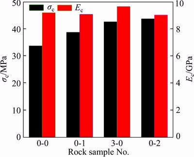
Fig. 8 Influence of filling type on ��c and Ec
It is clear that the overall strength of inclusion in the specimen 3-0 is higher than that of the specimen 0-1, but lower than that of the specimen 0-2, so its peak strength, 42.9 4 MPa, is higher than that of the specimen 0-1 but lower than that of the specimen 0-2. However, Ec of the specimen 3-0 is higher than that of the specimen 0-2 and specimen 0-0, which is probably caused by the heterogeneity characteristics of the inclusions and the rock specimens.
3.3.2 Influence of L on ��c and Ec
The variations of ��c and Ec with L are shown in Fig. 9 and the results suggest that there is an optimum ligament length. When L is shorter than 16 mm, ��c and Ec of all specimens go up with increasing L, reaching to the highest point when L is 16 mm, then both ��c and Ec turn to decline. Take specimens with �� of 45�� as an example,��c and Ec of the specimen 4-0 (L=16 mm) are 46.20 MPa and 9.72 GPa, being the maximum values. The ��c and Ec of the specimen 5-0 (L=20 mm) are 43.09 MPa and 8.98 GPa respectively, which are about 6.4% and 7.6% lower than those of the specimen 4-0.

Fig. 9 Influence of L on ��c and Ec:
3.3.3 Influence of �� on ��c and Ec
The variations of ��c and Ec versus �� are shown in Fig. 10. It can be seen from Fig. 10(a) that ��c of all specimens decline when �� increases from 45�� to 60�� and the reduction ranges from about 4.5% to 10.4%, then it turns to increase when �� increases to 75�� and the increase ranges is about 25%�C36.2%, suggesting that the variation curves of ��c with respect to �� show a ��V shape��. The variations of Ec are shown in Fig. 10(b), from which it can be seen that Ec increases gradually with the increase of �� from 45�� to 75��. To be more exact, Ec of specimens increases gently and linearly except for the specimen 5-2. The specimen 5-2 achieves about 10.7% increase in Ec when �� increases to 75��.

Fig. 10 Influence of �� on ��c and Ec:
JANEIRO et al [16] studied the variations of peak strength of gypsum specimens containing two circular holes along with the incline angle of ligament (��), three samples (1#, 2# and 3# specimens) were tested under each a , and the test results are shown in Fig. 11. As seen, the variations of ��c presented in this work is similar with that in Ref. [16]. However, some details are different. For example, ��c of gypsum specimens obtains minimum values at �� of 30��, while ��c in this work reaches the minimum values at �� of 60��, which is mainly caused by the differences in the specimen materials, the diameters of circular holes, and the mechanical properties of inclusions.

Fig. 11 Variations of ��c of gypsum samples containing fissures with different �� [16]
3.4 Variations of ��p
According to the analysis of crack propagation and final failure modes, one can see that the failure of ligament induces further propagation of cracks until failure of specimens, so the failure of rock mass can be effectively controlled if the rock mass can be reinforced timely when the local failure occurs. Thus, it is meaningful and helpful to discuss variations of ��p. The variations of ��p are shown in Fig. 12.
It is evident that, just like variations of ��c, ��p goes up with increasing L firstly and reaches to the highest point at L of 16 mm, then it shows a downward trend as L increases to 20 mm from 16 mm. Variations of ��p versus �� show a ��V shape��, which is also similar with those of ��c. Obviously, for rock specimens with a constant ��, the length of cracks that coalescent the ligament increases with increasing L, resulting in improved ��p, which affects the variations of ��c. Then boundary effect comes into play when L reaches to 20 mm, resulting in the modified failure mode of the ligament. As a result, both ��p and ��c decline when L increases to 20 mm from 16 mm (Fig. 9(a) and Fig. 12(a)). On the other hand, based on the distributions of two circular inclusions, one can see that compared with specimens with �� of 45��, ligaments between the two circular inclusions in specimens with �� of 60�� are too narrow to bear the external load. However, the effective bearing areas increase again as �� increases to 75�� from 60��. The above analysis explains why the variations of ��p and ��c are in the ��V�� shape.
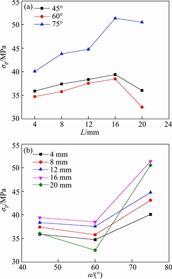
Fig. 12 Variations of ��p versus different L (a) and �� (b)
4 Conclusions
1) The initial cracks of sandstone specimens containing two circular holes filled with two types of inclusions under uniaxial compression mainly include wing crack, axial tensile crack and curved tensile crack. Failure modes of ligament of all specimens can be categorized as single inclined crack, the failure mode of single axial crack break mode and failure mode of two parallel cracks.
2) Failure of ligaments in specimens induces the propagation of cracks and final failure. The final failure modes can be categorized as tension-shear mixed failure and shearing failure. Strength property of inclusions shows little influence on the final failure modes, but the final failure modes vary with L and ��.
3) ��c and Ec of specimens with a fixed L show an upward trend firstly with the increasing L and reach the highest point at L of 16 mm, then decline. ��c decreases firstly with the increasing ��, then starts to increase, showing a ��V shape�� and Ec increases linearly with respect to ��.
4) ��p increases gradually with respect to the increase of L firstly and reaches the highest point at L of 16 mm, then shows a downward trend as L increases continually. And changing curves of ��p along with �� show a ��V shape�� as well.
References
[1] BOBET A, EINSTEIN H H. Fracture coalescence in rock-type material under uniaxial and biaxial compression [J]. International Journal of Rock Mechanics and Mining Sciences, 1998, 35(7): 863�C888.
[2] JING Hong-wen, SU Hai-jian, YANG Da-lin, WANG Chen, MENG Bo. Study of strength degradation law of damaged rock sample and its size effect [J]. Chinese Journal of Rock Mechanical and Engineering, 2012, 31(3): 543�C549. (in Chinese)
[3] ZHANG Ping, XU Jian-guang, LI Ning. Fatigue properties analysis of cracked rock based on fracture evolution process [J]. Journal of Central South University of Technology, 2008, 15(1): 95�C99.
[4] YANG S Q. Crack coalescence behavior of brittle sandstone samples containing two coplanar fissures in the process of deformation failure [J]. Engineering Fracture Mechanics, 2011, 78(17): 3059�C3081.
[5] BAUD P, WONG T F, ZHU W. Effects of porosity and crack density on the compressive strength of rocks [J]. International Journal of Rock Mechanics and Mining Sciences, 2014, 67: 202�C211.
[6] YIN P, WONG R H C, CHAU K T. Coalescence of two parallel pre-existing surface cracks in granite [J]. International Journal of Rock Mechanics and Mining Sciences, 2014, 68: 66�C84.
[7] LI K H, CAO P, ZHANG K, ZHONG Y F. Macro and meso characteristics evolution on shear behavior of rock joints [J]. Journal of Central South University, 2015, 22(8): 3087�C3096.
[8] KLEIN E, REUSCHLE T. A pore crack model for the mechanical behavior of porous granular rocks in the brittle deformation regime [J]. International Journal of Rock Mechanics and Mining Sciences, 2004, 41(6): 975�C986.
[9] KATCOFF C Z, GRAHAM-BRADY L L. Modeling dynamic brittle behavior of materials with circular flaws or pores [J]. International Journal of Rock Mechanics and Mining Sciences, 2014, 51(3): 754�C766.
[10] TANG C A, LIN P, WONG R H C, CHAU K T. Analysis of crack coalescence in rock-like material containing three flows-Part II: Numerical approach [J]. International Journal of Rock Mechanics and Mining Sciences, 2001, 38(7): 925�C939.
[11] ZHAO Y L, CAO P, WANG W J, WANG W, GHEN R. Wing crack model subjected to high hydraulic pressure and far field stresses and its numerical simulation [J]. Journal of Central South University of Technology, 2012, 19(2): 578�C585.
[12] ZAITSEV Y B, WITTMANN F H. Simulation of crack propagation and failure of concrete [J]. Materials and Structures, 1981, 83(14): 357�C365.
[13] TASDEMIR M A, MAJI A K, SHAH S P. Crack propagation in concrete under compression [J]. Journal of Engineering Mechanics, 1989, 116(5): 1058�C1076.
[14] ZHANG Bo, LI Shu-cai, YANG Xue-ying, WANG Gang, ZHANG Dun-fu, LI Jing-long. Uniaxial compression failure mechanism of jointed rock mass with cross-cracks [J]. Rock and Soil Mechanics, 2014, 35(7): 1863�C1870. (in Chinese)
[15] SU Hai-jian, JING Hong-wen, ZHAO Hong-hui, WANG Ying-chao. Experimental study on the influence of longitudinal fissure on mechanics characteristic of sandstone [J]. Journal of Mining and Safety Engineering, 2014, 31(4): 644�C649. (in Chinese)
[16] JANEIRO R P, EINSTEIN H H. Experimental study of the cracking behavior of specimens containing inclusions (under uniaxial compression) [J]. International Journal of Fracture, 2010, 164(1): 83�C102.
[17] YANG S Q, LIU X R, JING H W. Experimental investigation on fracture coalescence of red sandstone containing two unparallel fissures under uniaxial compression [J]. International Journal of Rock Mechanics and Mining Sciences, 2013, 63: 82�C92.
[18] YANG S Q, YANG D S, JING H W. An experimental study of the fractured coalescence behavior of brittle sandstone specimens containing three fissures [J]. Rock Mechanics and Rock Engineering, 2012, 45(4): 563�C582.
[19] WANG Guan-shi, HU Shi-li, LIU Hong-xing, ZHAO Kui. The damage process of rock-concrete interface by acoustic emission [J]. Mining Engineering, 2006, 4(4): 22�C24. (in Chinese)
[20] ZHANG Ping, LI Ning, HE Ruo-lan, XU Jian-guang. Mechanism of fracture coalescence between two pre-existing flaws under dynamic loading [J]. Chinese Journal of Rock mechanics and Engineering, 2006, 25(6): 1210�C1217. (in Chinese)
[21] PU Cheng-zhi, CAO Ping, YI Yong-liang. Fracture for rock-like materials with two transfixion fissures under uniaxial compression [J]. Journal of Central South University: Science and Technology, 2012, 43(7): 2708�C2716. (in Chinese)
(Edited by FANG Jing-hua)
Cite this article as:
DU Ming-rui, JING Hong-wen, SU Hai-jian, ZHU Tan-tan, CHEN Min-liang. Strength and failure characteristics of sandstone containing two circular holes filled with two types of inclusions under uniaxial compression [J]. Journal of Central South University, 2017, 24(11): 2487�C2495.
DOI:https://dx.doi.org/https://doi.org/10.1007/s11771-017-3661-zFoundation item: Project(2017YFC0603001) supported by the High-tech Research and Development Program of China; Project(51374198) supported by the National Natural Science Foundation of China
Received date: 2015-09-10; Accepted date: 2016-02-23
Corresponding author: JING Hong-wen, Professor; Tel: +86�C13805209187; E-mail: hwjing@cumt.edu.cn
Abstract: Plate shaped sandstones containing two fabricated circular holes that were filled with gypsum and high-strength concrete respectively were prepared for studying the effects of ligament length L ligament incline angle ��, as well as filling modes on their strength properties and failure modes. The results show that the initial cracks can be categorized as wing crack, axial tensile crack and curved tensile crack. The failure modes of ligaments can be categorized as mode of single inclined crack, mode of single axial crack and mode of two parallel cracks. The final failure modes of all specimens can be categorized as the tension-shear mixed failure and shear failure. The strength of inclusions shows little influence on the final failure modes of specimens, while the failure modes vary with L and ��. When �� is a fixed value, the peak strength ��c and elastic modulus Ec of tested specimens increase firstly with increasing L and reaches to the maximum value at L of 16 mm, then declines. When L is a fixed value, ��c declines firstly and then turns to increase as �� increases to 75�� from 45��, while Ec increases linearly. The axial stress ��p performs the similar variation trends with those of ��c versus increasing L and �� when ligaments fail.
