
J. Cent. South Univ. Technol. (2011) 18: 208-215
DOI: 10.1007/s11771-011-0681-y
![]()
Ultimate end bearing capacity of rock-socketed pile based on generalized nonlinear unified strength criterion
ZHANG Min(����), WANG Xing-hua(���ǻ�), WANG You(����)
School of Civil and Architectural Engineering, Central South University, Changsha 410075, China
? Central South University Press and Springer-Verlag Berlin Heidelberg 2011
Abstract:
In order to study the mechanism of bearing behavior at the tip of a pile embedded in rock, the generalized nonlinear unified strength criterion and slip line principle for resolving the differential equation systems which govern the stress field were applied to derive the ultimate end bearing capacity based on some reasonable hypothesis and failure plane model. Both numerical simulation and test results were compared with the theoretic solution. The results show good consistency with each other and verify the validity of the present approach. The depth effect with respective to embedment ratio and other influence factors like geological strength index, intermediate principal stress, overburden factor, and damage on end bearing capacity were discussed in the analytical solution. The results show that the proposed yield criterion can be much better for investigating the ultimate end bearing performance of rock-socketed pile. The end bearing capacity increases with embedment ratio and the increasing degree is influenced intensely by the above parameters. Furthermore, ignoring intermediate stress effect would underestimate the strength properties of the rock material and lead to a very conservative estimation value.
Key words:
1 Introduction
At present, the rock-socketed piles, which are widely applied in large-scale bridge foundation, towering structure foundation and high-rise building, gradually attract more and more attention in academic circles and engineering field and become a hotspot for study [1-3]. However, it is notoriously difficult to gain true ultimate bearing capacity of pile tip in reality because of its great bearing capacity, high testing cost and hard destructive test [4]. The determination of the ultimate end resistance, the choice of socketed depth, as well as varying regularity have not yet form a unified understanding among scholars. In 2002, SERRANOA and OLALLAB [5] studied the relationship between the ultimate bearing capacity and embedment ratio using Hoek-Brown model. RADHAKRISHNAN and LEUNG [6] believed that the socketed piles were generally in elastic state under work load and the end bearing capacity reduced with the increase of socketed depth, while the lateral friction increased. SONG and ZHENG [7] deemed that the end bearing gradually reduced with the rock-socketed depth and tended to obtain a certain value through analyzing the wealth of test pile data in soft soil ground.
The generalized nonlinear unified strength criterion was put forward by YU et al [8-9] and later applied into various fields [10-12]. It can be transited into many kinds of current frequently used constitutive models, such as the modified Hoek-Brown and the nonlinear unified strength theory and has achieved the unification of linear and non-linear unified strength criterion in mathematics. In addition, the dilatancy of rocks and the intermediate principal stress effect are taken into account, so that the criterion has a wider range of adaptability for strength estimating to intact rock materials as well as jointed rock masses.
In this study, the end bearing behavior of a pile embedded in rock was theoretically analyzed based on the slip line principle with considering rock mass damage, and the generalized nonlinear unified strength criterion was used as the constitutive model for bedrock. Then, the ultimate end bearing capacity was deduced and compared with both numerical and test results. The variation laws with embedment ratio and other major influence parameters affecting the end bearing performance were investigated finally.
2 Problem description
2.1 Generalized non-linear strength criterion considering rock damage
The constitutive relation of rock damage under LEMAITRE strain equivalence hypothesis [13] is as follows:
![]() (1)
(1)
where ��* and �� are the effective stress matrix and nominal stress matrix, respectively, D is the damage variable or damage factor reflecting the extent of rock damage.
Substituting the effective principal stresses ��1*, ��2* and ��3* for the nominal principal stresses ��1, ��2 and ��3, the generalized non-linear unified strength criterion [8] can be expressed as

where ��c is the uniaxial compressive strength of an intact rock material, b is the intermediate stress parameter which varies from 0 to 1, and m, s, a are the parameters of Hoek-Brown criterion. The parameter a varying from 0 to 1 can turn the criteria into unified yield criterion and other strength theory of different materials. For example, the above criteria adapt to soft rock foundation for 0.5
The magnitudes of m, s and a depend on the geological strength index (I) and were amended by HOEK et al [14] for many times and take the following forms:
 (3)
(3)
where I which characterizes the quality of the rock masses ranges from about 10 for extremely poor rock masses to 100 for intact rock; mi is a value reflecting the soft and hard degree of rock and can be obtained from experimental measures.
When b=0 and D=0, Eq.(2) will be degenerated into Hoek-Brown failure form:
![]() (4)
(4)
Using the LAMBE parameters p=(��1+��2)/2, q= (��1-��2)/2, and based on the plane strain and volume invariability hypothesis, the intermediate principal stress can be drawn as follows: ��2=(��1+��3)/2. Taking the above parameters, Eq.(2) can be rewritten as

According to Ref.[15], the instantaneous friction angle �� is defined in the following way:
![]() (6)
(6)
Based on the works of YU et al [9] and ��2=(��1+��3)/2, Eq.(5a) is applied to study this situation. Using Eq.(5a) and Eq.(6), the following expressions are obtained:
 (7)
(7)
Introducing the parameters ��=(ma)a/(1-a) and ��=s/ [m1/(1-a)aa/(1-a)], the above equations can be simplified as
 (8)
(8)
For the sake of facilitating the analysis, substituting p and q with p/��c and q/��c, respectively, make these parameters into dimensionless form.
2.2 Mechanical model
The plane strains bearing capacity problem under consideration is described in Fig.1. A circular pile with diameter B is embedded into a depth of HR under a homogeneous rock mass with unit weight ��R. The overlying soil layer with depth of HS and unit weight of ��S is treated as a constant overburden pressure HS��S applied on the top of the rock layer.
The Meyerhof solution for ultimate bearing capacity of deep foundation is used as a reference to the following analysis. When the foundation reaches the failure state, the slip surface starts from the pile tip, and then extends to the rock/soil interface and finally forms the symmetrical sliding mode, as shown in Fig.1. The slide region consists of three zones: active failure zone (O��AO), Prandtl transition zone (OAB) and passive failure zone (OBC). The surface OC with a inclination angle �� is assumed as virtual failure plane defined as boundary 1. To simplify this plane strain issue, the impact of three- dimensional space stress is neglected and the volumetric strain is assumed to be zero (i.e. ��2=(��1+��3)/2).
The above failure model was demonstrated to be acceptable for poor rocks (ultimate bearing capacity: ��hp��20-30 MPa) through comparing with about 33 sets of data obtained from in situ load tests conducted on piles until failure at the tip took place [16]. And also based on this model, a single pile embedded in sand was analyzed by LU et al [17] and the results were close to the observed data. In order to further simply the problem, the following basic hypotheses are used:
1) The rock mass is a homogeneous and isotropic medium and its failure is governed by the generalized nonlinear strength criterion.
2) The rock-socket section and the rock mass are separated from contact like a piston. That is to say, the interaction effect between side resistance and end bearing is neglected.
3) Due to the previous studies, the rock weight had a small effect on the bearing capacity compared with rock resistance itself so that the rock mass is assumed to be weightless.
2.3 Slip line method
The slip-line models in this work belong to sector slip-line field and the region OAB is assigned to be a degenerated Riemann��s problem. For the condition of straight and parallel slip lines, the parameters p, �� and stress components ��x, ��y, ��xy along these straight-lines are constant in the regions O��OA and OBC (Fig.1). According to Ref.[5], the following relationship enables to transfer the stress state from point 1 on boundary 1 to point 2 on boundary 2 along the �� slip-line:
I(��1)+��1=I(��2)+��2=constant (9)
In this formula,

derived with the method introduced by Ref.[15]; ��1 and ��2 represent the instantaneous friction angles for boundaries 1 and 2, respectively; ��1 and ��2 are the inclination angles of the main major stress ��1 for boundaries 1 and 2 (with respect to the vertical axis).
The variation characteristics of Riemann��s invariant I versus the principal stress coefficient b and instantaneous friction angle �� are shown in Fig.2.
Eq.(9) is the key to find the ultimate end resistance. Once the variable ��2 is obtained through solving the variables ��1 and ��1 of boundary 1 and the angle ��2 of boundary 2, it is possible to determine p2 and q2 of boundary 2 by Eq.(8). And the ultimate end bearing will
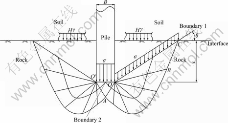
Fig.1 Sketch of slip-line field at pile tip
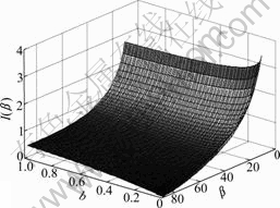
Fig.2 Relationship between I and b, ��
be finally obtained using the method introduced in the following section.
3 Analysis of ultimate end resistance and embedment ratio
3.1 Analysis of stresses on boundary 1
If this balance of rock mass at the pile tip is broken (i.e. the failure occurs), the rock would conduct a counter- clockwise rotational movement around point O and the stresses on boundary 1 are in passive state. The corresponding Mohr��s circle for boundary 1 matching the counterclockwise rotation kinematics is shown in Fig.3.
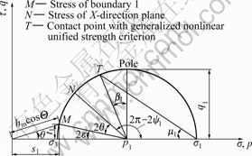
Fig.3 Mohr��s circle for boundary 1
The dip angle �� for virtual boundary 1 can be expressed in the following way [5]:
![]() (10)
(10)
where p1 and q1 are Lambe��s variables for boundary 1 (dimensionless); hm is the overburden coefficient and is
expressed as ![]()
Substituting Eq.(8) into the above equation, the instantaneous friction angle ��1 of boundary 1 can be obtained through iterative calculation with the given parameters a, b, ��, D, �� and hm, then the function I(��1) can be worked out.
3.2 Solution of ultimate bearing capacity
For the common non-tilt pile in actual engineering, the inclination ��2 of the main major stress at boundary 2 equals zero. The previous Eq.(9) allows ��2 to be obtained using the inverse function of Riemann��s Invariant:
![]() (11)
(11)
where �� is the angle that forms the main major stress ��1 with the inclination of the ground and can be expressed as
![]() (12)
(12)
Taking account of Eq.(8) and the formula ![]() the ultimate end bearing capacity ��h that is the purpose of the calculations for the entire process may be put as
the ultimate end bearing capacity ��h that is the purpose of the calculations for the entire process may be put as
![]() (13)
(13)
The non-dimensional parameter N�� is ultimate end bearing factor and can be obtained as

![]() (14)
(14)
3.3 Embedment ratio analysis
According to the geometric relation (Fig.1), the embedment ratio n can be written as [5]
![]() (15)
(15)
where ��1=��/4-��1/2. Eq.(15) provides the embedment ratio n as a function of the angle �� and the instantaneous friction angles at boundaries 1 and 2. Once the system formed by nonlinear Eqs.(9), (11) and (15) has been solved through iteration with a given embedment ratio n, the three unknown variables ��1, ��2, and �� can be gotten and the ultimate bearing capacity ��h can be obtained by Eq.(13) finally.
4 Comparison analysis
4.1 Comparison with numerical results
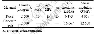
In order to demonstrate the correctness of this analytic formula, the numerical simulation is carried out to investigate the end bearing capacity of socketed drilled shaft. A single circular pile with diameter B= 1.00 m is embedded in a homogeneous rock layer. The impact of different rock-socketed length from 0 to 8 m is examined with the correspondent embedment ratio from 0 to 8. Considering the symmetry of load and structure, the grid is reduced in size by a two-fold symmetry. The overall sizes of the model are 0��x��6 m, 0��y��6 m, -14 m��z��0, and the finite difference mesh utilized in the analysis is illustrated in Fig.4, consisting of 676 brick elements and 991 nodes. At the bottom level of the computational domain, all movements are restrained, while at the lateral external sides, lateral movements perpendicular to the boundary are prohibited. To reflect the pile-soil interaction, interface elements are placed between the pile and the rock. A normal stiffness of 10 GPa and a tangential stiffness of 10 GPa are assumed for the interface properties. To enable the resistance only provided by the pile tip, the interface cohesion and friction are both set to be zero. The rocks are assumed to be elastic-plastic and represented by Hoek-Brown constitutive model. And a linear elastic constitutive model is used for the pile. The properties of these materials are summarized in Table 1.
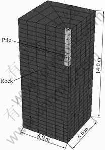
Fig.4 Mesh of calculation model
Table 1 Material properties for concrete pile foundation in rock
As the Hoek-Brown criterion used in the numerical simulation doesn��t take into account of the effect of principal stress and rock mass damage, b=0 and D=0 are taken in the above analytical formulas to compare with analytical solution under the same condition. Meanwhile, a shape coefficient s�� suggested by SERRANOA and OLALLAB [5] needs to be applied to reflect the three- dimensional geometry of the pile:
![]() (16)
(16)
where ��m is an average friction angle of boundary 1 and boundary 2, which can be derived by the following formula after obtaining ��1 and ��2:
![]() (17)
(17)
The ultimate end bearing capacity is obtained by imposing vertical velocity on the top nodes of pile. Fig.5 shows the distribution of shear strain increment. The failure plane is a space surface and does not extend to rock/soil interface as the previously assumed slide model in Fig.1. The reason for the difference is that the weight of rock mass and the three-dimensional stress state are both considered in the above numerical simulation, which makes the failure plane relatively more difficult to extend to the interface. The vertical stress-deflection curves of the pile under different embedment ratios are shown in Fig.6. When the stress at the pile tip no longer increases with the settlement, the bedrock is determined to reach limited equilibrium state and the corresponding counterforce is considered to be the ultimate end bearing capacity.
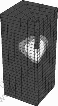
Fig.5 Distribution of shear strain increment
Fig.7 shows the analytic and numerical results of the bearing capacity factor as a function of embedment ratio n for a range of geological strength index I. The analytic results coincide well with the numerical results and the maximum difference does not exceed 10%. This
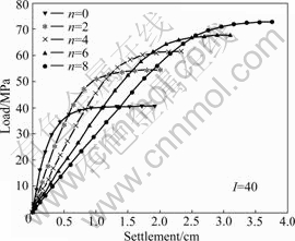
Fig.6 Load-settlement curves of piles under different embedment ratios
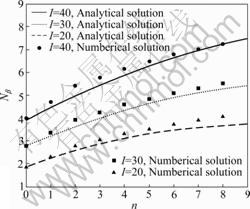
Fig.7 Calculated and numerical results of N��-n
indicates that the assumed model presented in this work is reasonable to study the end bearing capacity of rock-socketed pile. Furthermore, the ultimate end bearing capacity factor N�� increases with the embedment ratio n and grows more significantly for a higher geological strength index. Due to the increase of the rock strength, the same effect with the parameter I is observed for a given value of n.
4.2 Comparison with test results
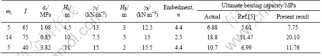
Table 2 shows the present results for b=1 and D=0 in comparison with the in situ test results, together with the results obtained by Hoek-Brown model in Ref.[5]. Due to neglecting the intermediate principal stress, the method developed in Ref.[5] underestimates the bearing capacity of rock mass, while the generalized nonlinear unified strength criterion provides the estimations that are closer to test results. This further demonstrates that the plastic failure hypothesis is reasonable for piles embedded in rock.
5 Results and discussion
5.1 Analysis of relationship between N��, �� and embedment ratio n
In order to study the effect of different parameters on bearing capacity, the data mi=25, I=40, overburden factor hm=0.01, intermediate principal stress coefficient b=1 are adopted in the following analysis without considering rock damage (i.e. D=0). During discussing a certain parameter, its value is changed and other parameters are kept invariable.
Fig.8 displays the ultimate end bearing factor N�� and the angle �� varying with n. It can be observed that the ultimate end bearing factor exhibits a trend of nonlinear incline with the embedment ratio. For a given pile diameter B, the ultimate end resistance increases with the rock-socketed depth. It is worthy of noticing that most current field test results [18-20] indicate that the end resistance or its proportion of the total load decreases with rock-socketed depth. The reason to clarify the confusion lies in that the end resistance data from the most field pile tests are only the corresponding contribution values of rock at pile tip when the side resistance reaches limit state that is generally earlier to reach. However, the end bearing capacity discussed in this work is an ultimate value when rock mass at the pile tip appears in failure.
As shown in Fig.8, the bearing capacity curve increases sharply when the dip angle �� approaches 90�� at point A with the increase of the embedment ratio n. Referred to this phenomenon, there is a limited embedment ratio with the corresponding dip angle ��=90��, over which the hypothetical failure mode will no longer be suitable and the overburden factor hm should be modified. Details regarding the analysis method are given in Ref.[5].
5.2 Influence of overburden factor on ultimate end bearing
The ultimate end bearing factors under different hm
Table 2 Present results in comparison with test results
values are presented in Fig.9. As the normal stress component of the overburden pressure on the edge OC restrains the anticlockwise slipping of the rock mass at the pile tip when reaching ultimate state, a larger overburden factor hm, namely a thicker overlaying soil layer, would make the restraining effect play more intensively and lead to a higher bearing capacity. When the dip angle �� reaches 90��, the surface OC coincides with the pile shaft and the overburden factor hm equals zero. Thus, the angle no longer has impact on the bearing capacity and all curves converge on one same point.
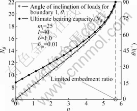
Fig.8 Relationships between N��, �� and n
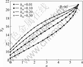
Fig.9 Relationships between N�� and n for different overburden factors
5.3 Influence of intermediate principal stress coefficient on ultimate end bearing
Although the ultimate bearing capacity is dealt with plane strain problem in the work, the rock foundation is under three dimensional stress states in reality. A large number of triaxial tests have proved that the rock strength and destruction are related not only with the maximum and minimum principal stress, but also closely with the intermediate principal stress, that is, the existing intermediate principal stress effect [8]. Fig.10 indicates that the bearing capacity factor increases non-linearly with b and a larger lateral restraint means a faster rising of N�� and a sooner reaching to the limit embedment ratio. It is worth noting that the end bearing capacity with b=0 increases with a high growth rate in early stage, then gradually with a slow increasing speed, and finally tends to be a stable value. This shows that the intermediate principal stress factor b has remarkable effect on the bearing capacity and can lead to a very reasonable estimation of the rock strength.
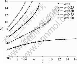
Fig.10 Relationships between N�� and n for different intermediate principal stress factors
5.4 Influence of damage factor on ultimate end bearing
The results of impact analysis with different damage factors D have been summarized in Fig.11. The variation law of N��-n implies that the bearing capacity factor can reach the maximum value without rock damage for the same embedment ratio and decreases with the accumulation of the damage. So, in the process of construction, it is critical to minimize the disturbance of rock at pile tip as possible to avoid bearing capacity loss due to the damage.
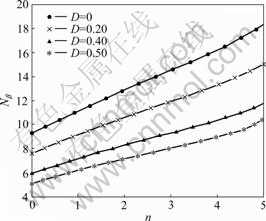
Fig.11 Relationships between N�� and n for different damage factors
6 Conclusions
1) Compared with the results of the case histories, the proposed generalized nonlinear unified strength criterion can be used to better investigate the ultimate end bearing capacity of socketed pile. Some constitutive relations like Hoek-Brown strength criterion used in the traditional analysis could be the special case of it.
2) The ultimate end bearing factor exhibits a trend of nonlinear growth with the embedment ratio. However, the pile tests demonstrate that the ratio of end resistance accounting for the total load declines with embedment ratio, which indicates the ultimate end bearing capacity cannot play fully for a great socketed depth and it is necessary to choose an economic and reasonable depth viewing the both variation laws in practice.
3) The intermediate stress parameter b has remarkable influence on the bearing performance of rock mass at pile tip. The effect of ignoring such fact would underestimate the strength properties of the rock material and lead to a very conservative estimation value.
4) The ultimate end bearing capacity increases with the overburden and decreases with the rock damage. Thicker overlaying soil layer and less disturbance of rock will be beneficial to enhancing the bearing performance.
References
[1] YANG Xiao-li, ZOU Jin-feng. Displacement and deformation analysis for uplift piles [J]. Journal of Central South University of Technology, 2008, 15(6): 906-910.
[2] SERRANOA A, OLALLAB C. Shaft resistance of piles in rock: Comparison between in situ test data and theory using the Hoek and Brown failure criterion [J]. International Journal of Rock Mechanics and Mining Sciences, 2006, 43: 826-830.
[3] SEOL H, JEONG S, KIM Y M. Load transfer analysis of rock-socketed drilled shafts by coupled soil resistance [J]. Computer and Geotechnics, 2009, 36: 446-453.
[4] ZHANG Jian-xin, WU Dong-yun, DU Hai-jin. Testing study on bearing behaviours and failure mode of rock-socked pile [J]. Journal of Rock Mechanics and Engineering, 2004, 23(2): 320-323. (in Chinese)
[5] SERRANOA A, OLALLAB C. Ultimate bearing capacity at the tip of a pile in rock��Part 1: Theory [J]. International Journal of Rock Mechanics and Mining Sciences, 2002, 39: 833-846.
[6] RADHAKRISHNAN H S, LEUNG C E. Load transfer behaviour of rock-socketed piles [J]. Journal of Geotechnical Engineering, ASCE 1989, 115: 755-768.
[7] SONG Ren-qian, ZHANG Zhong-miao. Study on socket length of rock-socketed piles in soft soil ground [J]. Rock and Soil Mechanics 2003, 24(6): 1053-1056. (in Chinese)
[8] YU Mao-hong, Zan Yue-wen, ZHAO Jian, MITSUTOSHI Y. A unified strength criterion for rock material [J]. International Journal of Rock Mechanics and Mining Sciences, 2002, 39: 833-846.
[9] YU Mao-hong, MA Guo-wei, QIANG Hong-fu, ZHANG Yong- qiang. Generalized plasticity [M]. Berlin: Springer, 2006: 56-58.
[10] ZHOU Xiao-ping, YANG Hai-qing, ZHANG Yong-xing, YU Mao-hong. The effect of the intermediate principal stress on the ultimate bearing capacity of a foundation on rock masses [J]. Computer and Geotechnics, 2009, 36: 861-870.
[11] LI JIan-chun, MA Guo-wei, YU Mao-hong. Penetration analysis for geo-material based on unified strength criterion [J]. International Journal of Impact Engineering, 2008, 35: 1154-1163.
[12] WANG Yan-bin, YU Mao-hong, YUN Xiao, LI Lin-sheng. Dynamic plastic response of a circular plate based on unified strength theory [J]. International Journal of Impact Engineering, 2005, 31: 25-40.
[13] LEMAITRE J, DESMORAT R. Engineering damage mechanics [M]. Berlin: Springer, 2005: 5-6.
[14] HOEK E, CARRANZA-TORRES C T, BRENT C. Hoek-Brown failure criterion-2002 edition [C]// Proceedings of the Fifth North American Rock Mechanics Symposium. Toronto, Canada, 2002: 267-273.
[15] SERRANO A, OLALLA C. Ultimate bearing capacity of rock masses [J]. International Journal of Rock Mechanics and Mining Sciences, 1994, 31: 93-106.
[16] SERRANOA A, OLALLAB C. Ultimate bearing capacity at the tip of a pile in rock��Part 2: Application [J]. International Journal of Rock Mechanics and Mining Sciences, 2002, 39: 847-866.
[17] LU Yan-er, ZHENG Jun-jie, CHEN Bao-guo. Determination of end bearing capacity of pile with double-shear slip-line theory [J]. Journal of Rock Mechanics and Engineering, 2007, 12(Supp.2): 4084-4089. (in Chinese)
[18] DONG Ping, QIN Ran, CHEN Qian, LIU Xiao-ming. Bearing behavior of large-diameter rock-socket piles [J]. Journal of Rock Mechanics and Engineering, 2003, 22(12): 2009-2103. (in Chinese)
[19] SHI Pei-dong, LING Jin-yu. Vertical bearing capacity of rock-socketed piles [J]. Journal of Geotechnical Engineering, 1994, 16(4): 32-39. (in Chinese)
[20] ROWE R K, ARMITAGE H H. Theoretical solutions for axial deformation of drilled shafts in rock [J]. Canadian Geotechnical Journal, 1987, 24(1): 114-125.
Foundation item: Project(2007AA11Z134) supported by the National High-tech Research and Development Program of China; Project(10JJ4035) supported by Hunan Provincial Natural Science Foundation of China; Project(04SK2008) supported by Hunan Provincial Science and Technology Department, China
Received date: 2009-12-22; Accepted date: 2010-06-04
Corresponding author: WANG Xing-hua, Professor, PhD; Tel: +86-731-82655489; E-mail: xhwang@mail.csu.edu.cn
