

Bonding mechanism of ultrasonic wedge bonding of copper wire on Au/Ni/Cu substrate
TIAN Yan-hong(����)1, WANG Chun-qing(������)1, Y. Norman ZHOU2
1. State Key Laboratory of Advanced Welding Production Technology, Harbin Institute of Technology,Harbin 150001, China;
2. Microjoining Laboratory, Center for Advanced Materials Joining, University of Waterloo,Waterloo, Canada, N2L 3G1
Received 31 December 2006; accepted 28 May 2007
Abstract:
The ultrasonic wedge bonding with d25 ��m copper wire was achieved on Au/Ni plated Cu substrate at ambient temperature. Ultrasonic wedge bonding mechanism was investigated by using SEM/EDX, pull test, shear test and microhardness test. The results show that the thinning of the Au layer occurs directly below the center of the bonding tool with the bonding power increasing. The interdiffusion between copper wire and Au metallization during the wedge bonding is assumed negligible, and the wedge bonding is achieved by wear action induced by ultrasonic vibration. The ultrasonic power contributes to enhance the deformation of copper wire due to ultrasonic softening effect which is then followed by the strain hardening of the copper wedge bonding.
Key words:
copper wire; ultrasonic wedge bonding; bonding mechanism; wear action;
1 Introduction
Copper wire bonding is an alternative chip interconnection technology with promising cost saving compared to gold wire bonding and better electrical performance compared to aluminum wire[1]. There are lots of studies on thermosonic gold ball bonding and ultrasonic aluminum wedge bonding[2-6]. However, a complete understanding of the bonding mechanisms is lacking, especially for the ultrasonic copper wedge bonding.
Ultrasonic wire bonding is generally accepted to be a solid state joining process which is supported by various evidence that the wedge bonding can be made at liquid nitrogen temperatures[7] and studies of the bond interface with transmission electron microscopy[8]. LEVINE[9] summarized the deformation and dislocation bonding mechanisms based on the ultrasonic softening effect proposed by LANGENCKER[10]. Dislocation theory proposed a new fresh metal surface formation mechanism by slip planes. However, this theory deals with the nano-scale of welding rather than observable metallurgical bond formation. Therefore, dislocation theory is insufficient to explain wire bond formation. Much recently, interdiffusion of Al/Ni system was also found to be enhanced by ultrasonic vibration[11]. LI et al[12] found the atomic diffusion at Au/Al bonded interface at a high level ultrasonic frequency (1.5 MHz) when the ultrasonic power was 1.75 W and bonding temperature was 200 ��.
The additional effect of ultrasonic energy may be the creation of relative motion between the wire and substrate as inferred by MAYER et al[13] utilizing in-situ microsensors. They showed that relative motion at the ball/substrate interface was important in bond formation. When no sliding occurred there was no bonding at ambient temperature. Recently, LUM et al[14] proposed the transition from microslip to gross slide with ultrasonic power increasing based on the micro-slip theory to elucidate the Au ball bonding mechanism on Cu substrate. Micro-slip theory incorporated elastic contact mechanics into the ultrasonic wire bonding mechanism, however, it did not take into account of any substantial contribution of plastic deformation during the bond formation.
Since there were no published studies of the bonding mechanisms in copper ultrasonic wedge bonding, this study was undertaken to gain a better understanding of the role of processing parameters in the ultrasonic copper wedge bond formation on Au/Ni plated copper substrate at ambient temperature. The cross sections of wedge bond and sheared fracture surfaces were observed with scanning electron microscopy(SEM), pull test and microhardness test of the wedge bonds were also performed.
2 Experimental
Copper wire bonding was performed at room temperature on Au/Ni plated Cu substrate with the Au thickness of 3 ?m, Ni 7 ?m and Cu 23 ?m. The d25 ?m copper wires were provided by MK Electron Co. Ltd with purity of 99.99%. The bonding machine used was a semi-automatical 4523A Digital K&S wedge bonder with a frequency of 65 kHz. The wedge used was a Kulicke and Soffa part #4WNV0-2020-W5C-M00. Fig.1 illustrates the Cu wire wedge bonding process. During the wedge bonding process, a horizontal ultrasonic vibration with a simultaneous normal bond force was utilized to form the first and second bonds at ambient temperature.
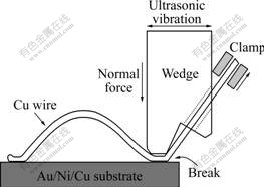
Fig.1 Schematic drawing of Cu wire wedge bonding process
After wedge bonding, pull test was performed on DAGE 4000 to get the pull force of the bond. For a parameters setting, 20 wedge bonds were tested. For the strong wedge bonds broken at neck position during the pull test, shear test was performed to investigate the bonding interface.
The cross section samples and fractured surfaces after shear test were observed using SEM, and energy dispersive X-ray(EDX) was used to study the interfacial atomic diffusion and to identify the chemical compositions. Vickers microhardness testing was conducted on the cross section of the copper wedge bonds at various locations. The method employed an indentation measurement by using a 136? diamond pyramid indenter. The load was 0.05 N and was applied for 15 s.
3 Results and discussion
3.1 Failure modes of wedge bonds
During the wedge bonding of the copper wire, three types of bonding outcomes are obtained: lift-off caused by weak bonding, sticking, and wedge bond cut caused by excessive deformation. Lifted off bonds would occur because the frictional force between the wire and wire feed hole during the following looping step would be greater than the strength of the wedge bond. On the other hand, if the bond is sufficiently strong, the wedge bond would stick on the substrate during the following looping step.
The failure mode of wedge bonds during pull test may give insight to the wire bondability and the bond strength. There are three failure modes:
1) Interfacial break (Bond lifting off from the surface of the metallization);
2) Neck break (Wire break at the neck of the bond);
3) Bond break (when the bond was deformed excessively).
Wire breaking at the neck position of the bond is the preferred mode in this experiment because a high wire load with a wire break indicates good bonding between the wire and the Au/Ni/Cu metallization. Bond break is not preferred because the bonds deform excessively under high bonding power and force. Fig.2 shows the pull test results and illustrates the different regions of failure modes. With 65 mW and less ultrasonic bonding power (labeled Lift off region), lift-off bonds would occur since the amount of bonding is minimal. Bond sticking would occur with ultrasonic bonding power higher than 65 mW. With increasing bonding power up to 390 mW, the percentage of interfacial break decreases and more neck breaks occur. It can be seen that the wedge bonds with the neck break failure modes yield the highest pull forces during pulling test.
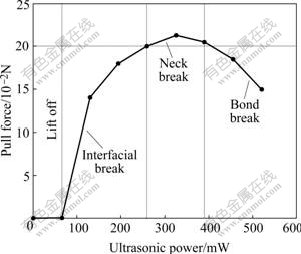
Fig.2 Plot of pull test results illustrating different regions of failure modes and resulting pull force with ultrasonic power
3.2 Cross section and fracture surfaces of wedge bonds
The possibility of using Cu wires bonding to Au/Ni plated Cu substrate has led to interest in the bonding mechanism and reliability of this metallurgical system. Fig.3 shows the cross sections of second bonds when the bonding force is 0.35 N, the bonding time is 30 ms and the ultrasonic power is 260 mW and 370 mW respectively. With the bonding power increasing, the thickness of the gold layer at the center of the Au/Ni metallization decreases, as shown in Fig.3(b). It seems that the ultrasonic power contributes to increased deformation of the copper wire because higher ultrasonic power makes the wire softer due to ultrasonic softening. Fig.4 shows two lines scan from the same cross sections of Figs.3(a) and (b), which indicates there is no obvious interdiffusion between Cu and Au at these two bonding interfaces. However, a little amount of Au elements inside the Cu wire is found, which may be caused by the wear action and mechanical mixing.
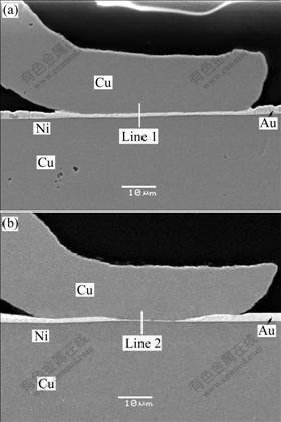
Fig.3 Cross section morphologies of second bonds with different bonding power showing thinning of Au layer occurs with ultrasonic power increasing: (a) 260 mW, 0.35 N, 30 ms; (b) 370 mW, 0.35 N, 30 ms
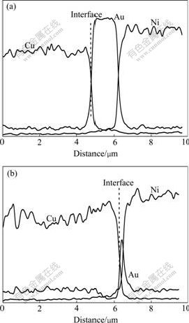
Fig.4 Results of line scan from same cross sections of Fig.3: (a) Line scan from Line 1 in Fig.3(a); (b) Line scan from Line 2 in Fig.3(b)
Fig.5 shows the sheared fracture surfaces. The sheared fracture surfaces show the typical ellipse shape of wedge bonding, as seen from Figs.5(a) and (c). Both of the fracture surfaces show dimples which indicate desirable ductile bonded joints. The element compositions of the fracture surface are mainly Au and Cu, which shows that the fracture occurs along the bonding interface between the Cu and Au layer. For 325 mW bonds, the top layer of Au/Ni metallization lifts off somewhere and the Cu substrate is exposed during shearing, which can be found from the EDX result of point A. Point B and point C show good bonding and mixing of the elements between wire and metallization, as shown in Fig.5(b). For the bonds with increased power of 370 mW, a small white particle is found at the fractured surface, as shown in Figs.5(c) and (d). The EDX result of point D shows that the particle consists of Cu and Au elements.
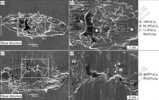
Fig.5 Fractured surfaces of wedge bond after shear test: (a), (b) 325 mW; (c), (d) 370 mW
There are three intermetallic phases (Cu3Au, CuAu, CuAu3) in the binary Cu-Au phase diagram when the temperature is beyond 200 ��. According to the literature, Cu moves rapidly through the Au film by boundary diffusion at temperatures of 100-300 �� within approximately 1 h, and the diffusion coefficient for Cu in Au is D=1.64��10-20 cm2/s at 200 ��[15]. This diffusion is faster than that of Au in Cu because the Cu atom is smaller than the Au atom. It was found from some ultrasonic wire bonding investigations that temperature rise at the bonding interface was 80-300 ��[16]. According to the Fick��s diffusion law, the thermal interdiffusion distance can be obtained from the following equation: X2=Dt, where t is the interdiffusion time, which is assumed as the bonding time, 50 ms, here. As a result, the thermal diffusion distance is not more than 0.03 nm. Therefore it is concluded that the Cu diffusion into the Au during the wedging bonding at ambient temperature is negligible, and the formation of IMCs is not expected.
The above results confirm that the mixing of the Cu and Au at the interface region and bonding at room temperature are related to a wear mechanism induced by the ultrasonic vibration. In ultrasonic wedge bonding, the amplitude of the bonding tip oscillation is proportional to the applied ultrasonic power and the relative motion experienced when the wire is sliding, will lead to wear of material (or contaminant) according to an equation developed for contacting surfaces in relative motion[17]:
![]() (1)
(1)
where t is the time required, d is the depth of worn material, p is the mean or nominal pressure, H is the hardness of the material, K is the wear coefficient constant, and v is the sliding velocity. During wedge bonding, the ultrasonic stick-slip friction causes friction power to be delivered at the interface. This power is partly transformed to mechanical wear. The wearing action breaks up contaminant and oxide layers allowing for areas of fresh metal of the opposing bonding partners to contact and bond to each other.
The rate and uniformity of the wear at the interface depend on the stress fields amplitudes and uniformity at the interface, respectively. The stress is lowest at the periphery region of the contact, and is highest at the bonding interface directly below the tool. Fig.6 shows the stress distribution at the wire/substrate interface for the wedge bonding. The thinning of the Au layer observed in Fig.3(b) can be explained by the larger interfacial peak stresses right below the wedge tool where the thinning is observed when the higher ultrasonic power is used.
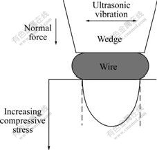
Fig.6 Stress distribution at wire/substrate interface for wedge bonding
The micrographs and plot of Vickers microhardness test results are given in Figs.7 and 8. The test was performed along the centerline of the copper wire. For the wedge bonds formed by the same processing parameters, five wedge bonds were tested and for each bond five points located at the wire part and the bonded joint part were tested. The Vickers hardness values are calculated using the following formula[18]: Vickers hardness(HV)=1.854 (F/D2), where F is the applied load of the indenter with a unit of kg, and D2 is the area of the indentation with a unit of mm2. It could be found that the hardness at the deformed bonding joint part is a little higher than that of the wire part, which is probably caused by the strain hardening of the wedge bond. It is believed that the ultrasonic energy enhances the plastic deformation of the bonding wire due to the fact that the dislocations inside the wire absorb the acoustic energy selectively, and the dislocations are activated from their anchoring locations, which makes the deformation of the bonding wire easier. After the acoustic energy is removed, the new defects make the bonding wire harder. There is no obvious difference between the microhardness of the wedge bonds formed by different ultrasonic powers, as shown in Fig.8.
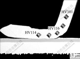
Fig.7 Indentation locations for microhardness tests of wedge bond under power of 260 mW, time of 50 ms and force of 0.35 N
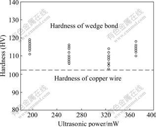
Fig.8 Vickers hardness of wedge bonds at different ultrasonic powers compared with hardness of copper wire
4 Conclusions
1) Copper wire bonding on an Au/Ni plated Cu substrate at ambient temperature is achieved. With the ultrasonic power increasing, the failure modes of the wedge bonds during pull test change from interfacial break to neck break and bond break. The wedge bonds with the neck break failure mode show good bonding quality and high pull force.
2) Cross section analysis shows a continuous connection between the Cu wire and Au metallization when the appropriate bonding parameters are chosen. With the increasing of the ultrasonic power, the thickness of the gold layer at the center of the metallization decreases. This is because the interfacial peak stresses occur right below the wedge tool where the thinning is observed.
3) The interdiffusion between Cu wire and Au layer at the bonding interface during the wedge bonding at ambient temperature is assumed negligible. The achievement of copper wedge bonding is proposed to be the wear action and mechanical mixing induced by the ultrasonic vibration. The ultrasonic power contributes to increasing deformation of the copper wire due to ultrasonic softening which was then followed by the strain hardening of the copper wedge bond.
References
[1] HARMAN G G. Wire bonding in microelectronics��Materials, processes, reliability, and yield [M]. 2nd Edition. New York: McGraw Hill, 1997.
[2] HO H M, LAM W, STOUKATCH S, RATCHEV P, VATH C J III, BEYNE E. Direct gold and copper wires bonding on copper [J]. Microelectronics Reliability, 2003, 43: 913-923.
[3] MURALI S, SRIKANTH N, VATH C J III. An analysis of intermetallics formation of gold and copper ball bonding on thermal aging [J]. Materials Research Bulletin, 2003, 38: 637-646.
[4] JI Hong-jun, LI Ming-yu, WANG Chun-qing, GUAN Jing-wei. Evolution of the bond interface during ultrasonic Al-Si wire wedge bonding process [J]. Journal of Materials Processing Technology, 2007, 182: 202-206.
[5] MURALI S, SRIKANTH N, VATH C J III. Grains, deformation substructures, and slip bands observed in thermosonic copper ball bonding [J]. Materials Characterization, 2003, 50: 39-50.
[6] LUM I, MAYER M, ZHOU Y. Footprint study of ultrasonic wedge-bonding with aluminum wire on copper substrate [J]. Journal of Electronic Materials, 2006, 35(3): 433-442.
[7] HARMAN G G, ALBERS J. Ultrasonic welding mechanism as applied to aluminum- and gold-wire bonding in microelectronics [J]. IEEE Trans Parts, Hybrids Packaging, 1977, 13: 406-411.
[8] KRZANOWSKI J E, MURDESHWAR N. Deformation and bonding processes in aluminium ultrasonic wire wedge bonding [J]. Journal of Electronic Materials, 1990, 19(9): 919-924.
[9] LEVINE L. The ultrasonic wedge bonding mechanism: Two theories converge[C]//Proceedings of the International Symposium on Microelectronics. Reston, VA, USA: ISHM Press, 1995: 128-131.
[10] LANGENECKER B. Effects of ultrasound on deformation characteristics of metals [J]. IEEE Trans Sonics Ultrasonic, 1966, 13(1): 1-8.
[11] LI Ming-yu, JI Hong-jun, WANG Chun-qing. Interdiffusion of Al-Ni system enhanced by ultrasonic vibration at ambient temperature [J]. Ultrasonics, 2006, 45: 61-65.
[12] LI Jun-hu, WANG Fu-liang, HAN Le, DUAN Ji-an, ZHONG Jue. Atomic diffusion properties in wire bonding [J]. Trans Nonferrous Met Soc China, 2006, 16: 463-466.
[13] MAYER M, PAUL O, BOLLIGER D. Integrated temperature microsensors for characterization and optimization of thermosonic ball bonding process[C]//Proceedings of the 1999 Electronic Components and Technology (ECTC). California, San Diego, 1999: 463-468.
[14] LUM I, JUNG J P, ZHOU Y. Bonding mechanism in ultrasonic gold ball bonds on copper substrate [J]. Metallurgical and Materials Transactions A, 2005, 36(5): 1279-1286.
[15] HALL P M, MORABITO J M. Diffusion problems in microelectronics packages [J]. Thin Solid Films, 1978, 53: 175-182.
[16] HO J R. Thin film thermal sensor for real time measurement of contact temperature during ultrasonic wire bonding process [J]. Sensors and Actuators A: Physical, 2004, 11(3): 188-195.
[17] PETERSON M B, WINER W O. Wear theory and mechanism from wear control handbook [M]. New York: The ASME United Engineering Center, 1980: 24.
[18] MUKERJI S, KAR T. Crystal research technology [M]. Germany: WILEY-VCH, 1999: 116.
Foundation item: Prpject(E052104/50705021) supported by the National Natural Science Foundation of China; Project(2006: 01504489) supported by the Development Program for Outstanding Young Teachers in HIT
Corresponding author: TIAN Yan-hong; Tel: +86-451-86418358; E-mail: tianyh@hit.edu.cn
(Edited by YUAN Sai-qian)
