

Feasibility of integrated seed making and directional solidification of
TiAl alloy using cold crucible
ZHANG Cheng-jun(�ųɾ�)1, 2, FU Heng-zhi(����־)1, XU Da-ming(�����)1,
GUO Jing-jie(������)1, BI Wei-sheng(����)1, SU Yan-qing(������)1
1. School of Materials Science and Engineering, Harbin Institute of Technology, Harbin 150001, China;
2. College of Materials Science and Engineering, Jiamusi University, Jiamusi 154007, China
Received 4 March 2008; accepted 21 July 2008
Abstract:
A new seed making method with cold crucible by power off technique was proposed. The cold crucible quenched seed with columnar structure has a similar cross-section shape as that of the cold crucible, and can be directly used for the directional solidification processes. The proposed method can significantly simplify the seeded directional solidification process and avoid the contamination from the seed machining.
Key words:
Ti alloy; seed making; crystal growth; cold crucible; directional solidification;
1 Introduction
As a potential high temperature structural material, TiAl-based alloys have attracted more and more attention because of their low density, high oxidation resistance and high-temperature strength. An alloy with fully lamella structure consisting of ��-TiAl phase and a small volume fraction of ��2-Ti3Al phase is found to possess the best mechanical properties if the lamellar orientation is aligned favorably according to the type of the load[1-6]. Therefore, many research efforts have been devoted to develop a method to control the solidifying structures of TiAl alloys and some significant progresses have been made. A successful method for lamellar orientation control is to use a seed to obtain a certain initial crystal orientation first and then let the subsequent solidification (usually directional solidification(DS)) of the ingot develop directly from the seed and keep the orientation of the grains in the seed[7-17].
Seed making is a key step in controlling the structure of TiAl-based alloys in directional solidification. There are several seed making methods developed by LEE et al[10]. The method of pouring molten metal into a permanent mold to obtain a cross-section columnar structure is the best one so far[6]. Moreover, on its cross section, the distribution of the lamellar orientations is like a cobweb because all columnar grains grow from outside towards the center[9]. Thus, the mechanical properties will be isotropy in the radial direction.
However, among these seed making methods, a seed ingot has to be prepared first and the seed is cut from the ingot for directional solidification. Therefore, the whole directional solidification processes are relatively complex and the seed is very likely to be contaminated during the cutting process.
The structure of a qualified seed should be composed of columnar grains. The lamella of a columnar grain is usually vertical to its axial because the favorable growth direction of ��-Ti3Al is (0001). The structure of a directional solidification sample will grow directly from the sides of the columnar grains to produce a lamellar structure parallel to the growth direction of the directional solidification. Therefore, the axial directions of all columnar grains near the solidification starting interface in the seed must be vertical to the direction of the directional solidification.
The main purpose of this work was to make a proper columnar structure of alloy suitable for seeding, and to study the feasibility to integrate seed making and directional solidification. To simplify seeding process and overcome the problems in the process of directional solidification, a new seed making method, using cold crucible with a power off technique, was proposed in this work. The high cooling ability of cold crucible can lead to a cross-section structure in a larger grain (about d 30 mm in the present research and about d 20 mm in Ref.[9]), which will be beneficial for production with seeding. The shape of the seed may change according to the cold crucible. Therefore, the seed can be directly used for the subsequent directional solidification without cutting. The columnar grains grow from the side-wall near the cold crucible towards the center within the seed zone. This will avoid the aeolotropy of mechanical properties on the cross section of the subsequently crystallized ingots/samples.
2 Experimental
2.1 Preparation of materials
To make a proper columnar structure of alloy suitable for seeding, the composition must be suitable for seeding. If the composition is not suitable, most of the solidified lamellar orientations in the seed will not be parallel to the direction of the subsequent directional solidification.
Fig.1 shows a binary phase diagram of Ti-Al alloy[7]. It can be seen that if the composition is lower than that of the peritectic point C1, the ��-phase will form in the seed during the remelting and solidification, so the ��-phase in the directional solidification will not grow directly from the ��-phase in the seed. On the other hand, if the composition is over C1 for a certain extent, the directional solidified structure will become full ��-phase in the subsequent cooling around the temperature where ������2 transformation takes place. Although the ��2-phase will form again during the cooling, the possibility to keep the orientation of the original ��-phase is only one forth because there are four pairs of different crystal faces in the ��-phase suitable for the ��2-phase to form and only one pair of them keeps the orientation of the original ��-phase[4].
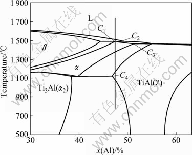
Fig.1 A binary phase diagram of Ti-Al alloy[7]
Fig.1 shows that even if the composition is C1 or slightly less than C1 the solidified structure still will become full ��-phase in the subsequent cooling. This means that a seed material should be a multi-component alloy. Therefore, to make a seed for the directional solidification of TiAl alloys, the composition of a seed material must be controlled carefully. The suitable composition for seeding should be around the peritectic point (C1). There are several kinds of composition combinations suitable for seed making reported in Refs.[1, 3].
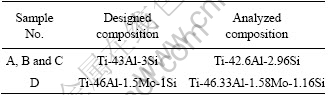
In this research, two compositions were selected as the seed materials according to the compositions given in Refs.[1, 3]. Ti-43%Al-3%Si alloys were selected as seed material for samples A, B and C, and Ti-46%Al- 1.5%Mo-1.2%Si was selected as seed material for sample D. The alloys were melted from pure Ti (99.79%), Al (99.99%), Mo (99.95%) and Si (99.6%) in a vacuum induction furnace. The ingots were cast into bars with a diameter of 100 mm and height of about 200 mm, from which the seeding materials were cut. The diameter of the sample was 30 mm and height was 60-80 mm. The actual compositions of the samples by chemical analysis are listed in Table 1.
Table 1 Seed compositions used in this work (molar fraction, %)
2.2 Seed making
To make a seed successfully, a cross-section columnar structure must be ensured. This requires a strong cooling ability of the mold and a relatively low temperature of the molten metal for a certain seed alloy. In the present work, the temperature was adjusted by controlling the heating power determined by preliminary experiments. A cold crucible was used to provide a strong quenching cooling. Fig.2 shows a sketch of seed making in crucible in the present work.
The bar of seed material should be located in the cavity of the crucible properly according to the size of the sample. The amount of molten metal was controlled to form a seed of about d 30 mm��(25-30) mm, which was suitable for subsequent directional solidification.
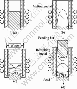
Fig.2 Sketch map of seed making process: (a) Before heating; (b) On melting; (c) After cooling; (d) Starting to directional solidification
The seed material was heated in a vacuum induction furnace that was mainly used for directional solidification. For sample A, the power was increased gradually to 60 kW and held for 5 min. Then, the power was turned off suddenly. The molten metal was cooled in the cold crucible to make a seed.
For samples B, C and D, the power was increased gradually to 60 kW and held for 3 min. Then, it was decreased to 55 kW. After 5 min, the power was turned off suddenly.
2.3 Integration of seed making and directional solidification
To study the feasibility to integrate seed making and directional solidification, sample D was remelted and directionally solidified. Fig.2(d) shows a scheme of the directional solidification. After the power off at about 10 min in the seed making, the seed was drawn downwards a distance of about 15 mm, which was determined through experiment to ensure the remelted interface in the cross-section columnar zone. A feeding bar was used to keep the volume of the molten metal constant. Then, the upper part of the seed was remelted and the feeding bar was sent downwards to establish an initial volume of molten metal.
After the seed was remelted for 5 min and the molten metal reached a certain amount, the seed was drawn downwards and the feeding bar was sent accordingly. The heating power was 55 kW and the drawing speed was 12 mm/h in the directional solidification. The feeding speed was determined according to the drawing speed and the ratio of section areas of the feeding bar and the sample. In this work, the ratio of section areas of the feeding bar to the sample was 0.8 so that the feeding speed was 15 mm/h.
3 Results and discussion
Samples A and B were cut along the longitudinal sections. And sample C was cut along the cross section. After grinding, the samples were eroded with an etching agent of 4%HF, 4%HNO3 and 92%H2O (volume fraction). The macrostructures of samples A, B and C are given in Fig.3.
From Fig.3(a), it can be seen that there is well- developed columnar structure in the sample. But, a big shrinkage cavity prevents to form a cross-section structure, which is caused by the volume contraction of molten metal at a higher temperature during the solidification. The big shrinkage cavity makes the seed useless in the subsequent directional solidification with cold crucible. Because the lower part of the sample is not remelted, some columnar grains grow from it upwards or slantwise. This part is not suitable for the subsequent directional solidification as seed.
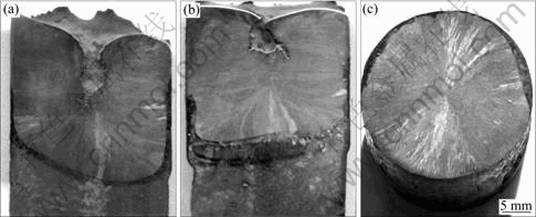
Fig.3 Cross-section columnar structure in seeds making through cold crucible: (a) Sample A, longitudinal section; (b) Sample B, longitudinal section; (c) Sample C, cross section
To make a qualified seed, there must be a cross- section columnar grain zone, which may be called valid seed zone, between the lower upward or inclined grain zone and the upper shrinkage cavity zone. Therefore,
either more molten metal or smaller shrinkage cavity is required to form a valid seed zone. Due to the limitation of the cold crucible size, only about 10% of molten metal was increased. To avoid the big shrinkage cavity, the heating power was adjusted to obtain different temperatures of the molten metal. A final heating power of 55 kW was determined by experiment in the present work to decrease the temperature of the molten alloys.
Fig.3(b) indicates that the shrinkage cavity is much smaller than that of sample A and a valid seed zone is developed with width of about 4.5 mm. This zone can be employed as seed for subsequent directional solidification. Fig.3(c) shows the cross-section macro- structure of sample C made at the same conditions as those of sample B. It is clear that a cross-section columnar structure is formed throughout the section. This indicates that the structure is suitable for seeding. And the web-like columnar structure can avoid the aeolotropy of mechanical properties in the cross-section.
The microstructure of sample B in the valid seed zone was observed with SEM (JSM-6360LV). The microstructures of sample B are shown in Fig.4. The microstructures of sample B show that the lamellar orientations of the columnar grains in the cross-section zone are nearly parallel to the direction of directional solidification. Therefore, with the help of a cold crucible, a seed-making by the new method is qualified both in macrostructure and in microstructure.
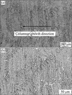
Fig.4 Microstructures of sample B in cross-section structure zone: (a) Lower magnification; (b) Higher magnification
To study the stability of the columnar structure, sample D was remelted partly at the position of valid seed zone and directionally solidified. Fig.5 shows the interface between the seed and the remelted zone of sample D. It can be seen that the columnar structure at the interface in the seed remains after the seed was partly remelted, indicating that this columnar structure is qualified for seeding. Fig.6 shows the microstructure at the interface. It can be seen that the lamella of the columnar structure keeps its orientation after the sample was partly remelted. From Fig.6, the lamella in the seed can grow directly into the directionally solidified part. This means that the seed is qualified and the seed making method is successful. This seed making method has been developed in Ref.[6].
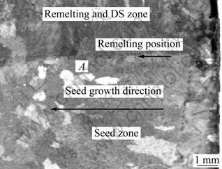
Fig.5 Interface between seed and remelting zone of sample D (Area A includes remelting interface)
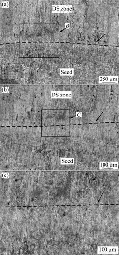
Fig.6 SEM images at interface between seed and remelting zone of sample D (Arrows pointed lines denote remelting interfaces): (a) Position A in Fig.5; (b) Position B in (a); (c) Position C in (b)
Because it is made in an induction furnace for directional solidification, the seed can be used directly for directional solidification without machining. Thus, the contamination caused by machining is eliminated. Moreover, this method can combine seed making with directional solidification so that the total process can be simplified significantly, which is a potential advantage of this method in industrial application.
4 Conclusions
1) Cold crucible technique can be used to produce TiAl-based alloy seed with throughout cross-section columnar gain structure of at least up to d 30 mm, if properly adjusting the amount of molten metal and the melting temperature. The web-like columnar structure in the seed can avoid the aeolotropy of mechanical properties on the cross-section of the directionally solidified samples effectively.
2) The presently proposed method for integrated seed making and directional solidification is feasible, which can avoid the machining contamination and significantly simplify the seeded directional solidification process.
References
[1] Lee H N, Johnson D R, Inui H, Oh M H, Wee D M, Yamaguchi M. A composition window in the TiAl-Mo-Si system suitable for lamellar structure control through seeding and directional solidification [J]. Mater Sci Eng A, 2002, 329/331: 19-24.
[2] FU Heng-zhi, GUO Jing-jie, SU Yan-qing, LIU Lin, XU Da-ming, LI Jin-shan. Directional solidification and lamellar orientation control of TiAl intermetallics [J]. The Chinese Journal of Nonferrous Metals, 2003, 13(4): 797-810. (in Chinese)
[3] Johnson D R, Inui H, Yamaguchi M. Directional solidification and microstructural control of the TiAl/Ti3Al lamellar microstructure in TiAl-Si alloys [J]. Acta Materialia, 1996, 44: 2523-2535.
[4] FU Heng-zhi, SU Yan-qing, GUO Jing-jie, XU Da-ming. The solidification behavior of high temperature intermetallics [J]. Acta Metallurgica Sinica, 2002, 38: 1127-1132. (in Chinese)
[5] KIM W S, KUMAR K S, OH M H, WEE D M. Crack propagation behavior in TiAl-Nb single and Bi-PST crystals [J]. Intermetallics, 2007, 15(7): 976-984.
[6] Kim S E, Lee Y T, Oh M H, Inui H, Yamaguchi M. Directional solidification of TiAl base alloys using a polycrystalline seed [J]. Mater Sci Eng A, 2002, 329/331: 25-30.
[7] Yamaguchi M, Johnson D R, Lee H N, Inui H. Directional solidification of TiAl-base alloys [J]. Intermetallics, 2000, 8: 511-517.
[8] Yamanaka T, Johnson D R, Inui H, Yamaguchi M. Directional solidification of TiAl-Re-Si alloys with aligned ��/��2 lamellar microstructures [J]. Intermetallics, 1999, 7: 779-784.
[9] Kim S E, Lee Y T, Oh M H, Inui H, YAMAGUCHI M. Directional solidification of TiAl-Si alloys using a polycrystalline seed [J]. Intermetallics, 2000, 8: 399-405.
[10] Lee H N, Johnson D R, Inui H, Oh M H, Wee D M, Yamaguchi M. Microstructural control through seeding and directional solidification of TiAl alloys containing Mo and C [J]. Acta Materialia, 2000, 48: 3221-3233.
[11] Johnson D R, INUI H, Muto S, Omiya Y, Yamanaka T. Microstructural development during directional solidification of ��-seeded TiAl alloys [J]. Acta Materialia, 2006, 54: 1077-1085.
[12] LUO Wen-zhong, SHEN Jun, LI Qing-lin, MAN Wei-wei, FU Heng-zhi. Microstructural evolution of Ti-47Al alloy during directional solidification by seeding method [J]. Acta Metallurgica Sinica, 2007, 43(9): 897-902. (in Chinese)
[13] LUO Wen-zhong, SHEN Jun, LI Qing-lin, FU Heng-zhi. Preparation of aligned lamellar microstructure in TiAl alloys by directional solidification with a seed technique [J]. Acta Metallurgica Sinica, 2007, 43(12): 1287-1292. (in Chinese)
[14] DING Hong-sheng, CHEN Rui-run, GUO Jing-jie, BI Wei-sheng, XU Da-ming, FU Heng-zhi. Directional solidification of titanium alloys by electromagnetic confinement in cold crucible [J]. Materials Letters, 2005, 59(7): 741-745.
[15] SAARI H, BEDDOES J, SEO D, ZHAO Y L. Development of directionally solidified ��-TiAl structures [J]. Intermetallics, 2005, 13(9): 937-943.
[16] ZHANG C J, XU D M, FU H Z, BI W S, SU Y Q, GUO J J. To eliminate the composition transient zone in directional solidification of TiAl alloys [J]. Journal of Crystal Growth, 2008, 310(15): 3604-3609.
[17] LUO Wen-zhong, SHEN Jun, LI Qing-lin, MAN Wei-wei, ZHENG Xun-qiang, LIU Lin, FU Heng-zhi. Effects of growth rate on microstructure of directionally solidified Ti-43Al-3Si alloy with a seed technique [J]. Acta Metallurgica Sinica, 2006, 42(12): 1238-1242. (in Chinese)
Foundation item: Project(50395102) supported by the National Natural Science Foundation of China
Corresponding author: ZHANG Cheng-jun; Tel: +86-451-86896351; Fax: +86-451-86221048; E-mail: chjunzhang@163.com
DOI: 10.1016/S1003-6326(08)60273-3
(Edited by YANG Hua)
