
Trans. Nonferrous Met. Soc. China 28(2018) 989-997
Computation of synthetic surface heat transfer coefficient of 7B50 ultra-high-strength aluminum alloy during spray quenching
Lei KANG1, Gang ZHAO1, Ni TIAN1, Hai-tao ZHANG2
1. Key Laboratory for Anisotropy and Texture of Materials, Ministry of Education, School of Materials Science and Engineering, Northeastern University, Shenyang 110819, China;
2. Key Laboratory of Electromagnetic Processing of Materials, Ministry of Education, School of Materials Science and Engineering, Northeastern University, Shenyang 110819, China
Received 14 November 2016; accepted 29 June 2017
Abstract:
According to inverse heat transfer theory, the evolutions of synthetic surface heat transfer coefficient (SSHTC) of the quenching surface of 7B50 alloy during water-spray quenching were simulated by the ProCAST software based on accurate cooling curves measured by the modified Jominy specimen and temperature-dependent thermo-physical properties of 7B50 alloy calculated using the JMatPro software. Results show that the average cooling rate at 6 mm from the quenching surface and 420-230 ��C (quench sensitive temperature range) is 45.78 ��C/s. The peak-value of the SSHTC is 69 kW/(m2��K) obtained at spray quenching for 0.4 s and the corresponding temperature of the quenching surface is 160 ��C. In the initial stage of spray quenching, the phenomenon called ��temperature plateau�� appears on the cooling curve of the quenching surface. The temperature range of this plateau is 160-170 ��C with the duration about 3 s. During the temperature plateau, heat transfer mechanism of the quenching surface transforms from nucleate boiling regime to single-phase convective regime.
Key words:
7B50 aluminum alloy; water-spray quenching; inverse heat transfer theory; synthetic surface heat transfer coefficient; cooling curve;
1 Introduction
7B50 alloys, as one of 7xxx series ultra-high- strength aluminum alloys, are widely used in the aerospace industry due to their excellent properties [1-3]. Because of the increasing size and integration of aviation components [4], the thickness of 7B50 alloy plates has been increasing. To the 7B50 alloy plates with big thickness, their quenching process after solid solution treatment is the key fact to the whole heat treatment process [5,6], whose cooling rate should be generally proper high enough to obtain the supersaturated solid solution after quenching. However, the over-high cooling rate during quenching process can cause large quenching stress inside of the plates, leading to the distortion, deformation and even cracking [7]. The evolutions of cooling rates in thick plates can be described by the synthetic surface heat transfer coefficient (SSHTC) of the quenching surfaces. Therefore, it is important to obtain the data of the SSHTC for calculating and predicting the actual quenching effects of the thick plates [8-10].
Up to date, the SSHTC of the quenching surface is mainly calculated using the inverse heat transfer theory based on measured cooling curves in quenching workpieces [11-13]. The specific calculation methods include the lumped heat capacity method [10,14], finite difference method [15,16], boundary element method [17,18] and artificial neural network method [19], etc. Many studies have been performed to calculate the SSHTC and investigate the factors affecting the SSHTC. XIAO et al [20] obtained the SSHTC of the quenching surfaces at different orientations of aluminum casting during immersion quenching. XU et al [21] discussed the effects of quenching surface roughness and water pressure on the SSHTC of 6082 alloy. YANG et al [8] investigated the influence of water temperature on the SSHTC of A357 alloy cylindrical bars. ULYSSE et al [22] reported the effect of coatings on the SSHTC of 7075 alloy cylindrical probes. By using the finite element method (FEM), LI et al [23] studied the evolutions of the SSHTC, surface hardness and surface residual stress of 40Cr steel specimens during quenching by high pressure nitrogen.
In recent years, the FEM has been developed greatly due to the rapid improvement on computer hardware and software. Because of the high computational accuracy of modern FEM software, the precision of the calculated SSHTC mainly depends on measured cooling curves in workpieces. However, the existing methods for measuring the cooling curves in workpieces of aluminum alloys have many limitations. For instance, thermo- couples are difficult to install accurately to record temperature-time data and the contact between thermocouples and the workpiece is poor. Besides, the thermocouples are lack of necessary insulation to avoid the interference from outside enviroment [24]. All these restrictions lead to that the measured cooling curves cannot reflect the actual quenching process of the workpiece.
In the present work, with the accurately measured cooling curves during water-spray quenching in the modified Jominy specimen [24,25] of 7B50 alloy and the temperature-dependent properties of this alloy calculated using the JMatPro software, the SSHTC of the quenching surface was calculated by the ProCAST finite element software. The evolutions of the SSHTC with quenching time and surface temperature during water-spray quenching were obtained aiming to provide essential data for calculating and predicting the quenching effects of 7B50 alloy thick plates.
2 Model description
2.1 Basic equations of heat transfer process
According to the Fourier law and energy conservation law, the heat conduction equation for transient problems can be described in rectangular coordinates as follows [23]:
 (1)
(1)
where l is the thermal conductivity, T is the thermodynamic temperature of the specimen, r is the density of the material, cp is the specific heat capacity at constant pressure, t is the quenching time and qv is the latent heat of phase transformation in per unit volume. As the water-spray quenching process inhibits the formation of precipitates in specimens, qv can be set to zero.
The initial condition of numerical simulation of heat transfer process is the initial temperature field of the specimen, which is the starting point of calculation and can be expressed as follows:
 (2)
(2)
where T(x, y, z, t) is the temperature field of the specimen, which is a function of space coordinates (x, y, z) and quenching time (t). In the present work, the initial condition of spray quenching process is the initial temperature field of the modified Jominy specimen before quenching, which is a uniform temperature field with the solution treatment temperature.
The heat transfer boundary condition describes the mode of heat exchange between the quenching surface and quenching medium. In the present work, the heat transfer boundary condition of the spray quenching process is defined as the third type condition including the convection and radiation heat transfer processes, which can be expressed as
 (3)
(3)
where q" is the heat flux density, hconv is the convection coefficient, hrad is the radiation coefficient, h is the SSHTC, Ts is the temperature of the quenching surface and Tq is the temperature of quenching medium. The SSHTC (h) is the synthetic equivalent coefficient including the convection and radiation heat transfer coefficients to accurately describe the complex heat transfer process on the quenching surface. In the present work, during water-spray quenching, the SSHTC of the quenching surface is much larger than the heat transfer coefficient of non-quenching surfaces cooled at ambient temperature. Therefore, heat transfer process of the specimen can be simplified as one-dimensional heat transfer along the axial direction of the specimen. In simulation process, heat transfer boundary condition of the quenching surface should be set as the SSHTC while heat transfer boundary condition of the non-quenching surfaces should be set as either air-cooling or adiabatic condition, which has little effect on the final simulation results.
2.2 Ideas and procedures of finite element modeling
Figure 1 shows the flow charts of two different methods of finite element analysis. The direct modeling method (Fig. 1(a)) represents the solving process of general problems. Based on the geometry model divided into elements, the data of material properties, initial conditions and boundary conditions, the calculation results such as temperature field of the specimen can be obtained by finite element software. Compared with the direct modeling method, the inverse modeling method of finite element analysis (Fig. 1(b)) can be used to estimate the unknown boundary conditions in experiments. When internal temperature field (cooling curves) of the specimen has been experimentally measured and the heat transfer boundary conditions in the experiment need to be estimated, the inverse modeling method can be used.

Fig. 1 Flow charts of different methods of finite element analysis
In the present work, the ��thermal history�� which is the temperature field (cooling curves) of 7B50 alloy thick plates is accurately measured using the modified Jominy specimen during water-spray quenching. The purpose is to obtain the heat transfer ��boundary conditions�� which are the relationships between the SSHTC of the quenching surface and quenching time and surface temperature. The initial SSHTC curve is calculated by the inverse calculation module of the ProCAST software. When the initial SSHTC curve is used as the heat transfer boundary condition, the cooling curve nearest the quenching surface can be obtained using the direct calculation module. Comparison and analysis of the calculated cooling curve with the corresponding measured cooling curve by the nonlinear estimation method, the initial SSHTC curve is repeatedly modified to ensure that the calculated cooling curve nearest the quenching surface is close to the measured cooling curve. When the difference between the calculated and measured cooling curves is less than the convergent condition, the final SSHTC curve of the quenching surface can describe actual characteristics of the heat transfer process between the quenching surface and quenching medium during water-spray quenching.
3 Experimental
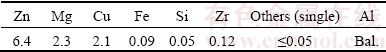
The material used in the present work was a hot-rolled 7B50 alloy plate with 80 mm in thickness and its chemical composition is shown in Table 1. The modified Jominy specimen with the effective size of d70 mm �� 170 mm was made of this plate and its axial direction was parallel to the rolling direction of the plate. The shape of the modified specimen was similar to the widely used Jominy specimen in steel industry [26,27], but the modified specimen could be divided into two parts making more convenient to install thermocouples accurately and firmly along axis of the specimen. The picture, assembly diagram, finite element geometry model of the specimen and experimental devices are shown in Fig. 2.
Table 1 Chemical composition of 7B50 aluminum alloy (mass fraction, %)
Seven NiCr-NiSi type thermocouples were installed at the bottom of the groove in the specimen (Fig. 2(a)) by the way of drilling and riveting with the distance of 6, 10, 15, 25, 35, 65 and 100 mm, respectively, from the spray quenching surface (Fig. 2(b)). The diameter of thermocouple wire was 0.254 mm and dynamic response time of the thermocouple was 0.05 s. After the thermocouples were installed, two parts of the specimen were bolted together at the bottom with bolts made of the same alloy and fastened in circumferential direction of the specimen. The shape and size of the modified Jominy specimen are shown in Fig. 2(c). According to the symmetry of the specimen, 1/2 geometry model of the specimen was established by the ProCAST software and then it was divided into 3 mm elements which were main hexahedron elements and a few wedge elements, as shown in Fig. 2(d). The specimen was solution-treated with two steps ((470 ��C, 2 h) + (483 ��C, 4 h)), and then transferred to the quenching devices within 5 s for water-spray quenching tests by spraying-water at about 20 ��C, as shown in Fig. 2(e). The diameter of the spray nozzle was 12.5 mm and the distance between the nozzle and the quenching surface was 12.5 mm. The height of water jet without the specimen was 90 mm. The temperature-time data during water-spray quenching tests were collected by a HIOKI 8430-21 data recorder and acquisition frequency was set to be 10 Hz.
4 Results and discussion
4.1 Relationship between thermo-physical properties of 7B50 alloy and temperature
The thermo-physical properties of 7B50 alloy at different temperatures are calculated using the JMatPro software and the results are shown in Fig. 3. It can be seen that the thermo-physical properties of 7B50 alloy, such as thermal conductivity, density, specific heat capacity and Poisson ratio change obviously with increasing the temperature. Therefore, the calculated temperature field of the specimen will be more accurate and closer to the tested results by using these temperature-dependent thermo-physical properties of 7B50 alloy.
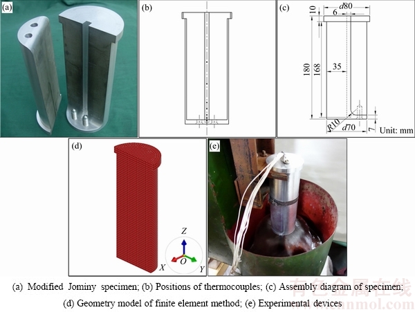
Fig. 2 Schematic diagrams of specimen and experimental devices of water-spray quenching
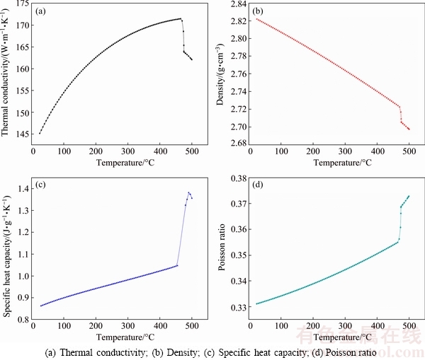
Fig. 3 Temperature-dependent thermo-physical properties of 7B50 alloy
4.2 Measurement of temperature field during water- spray quenching
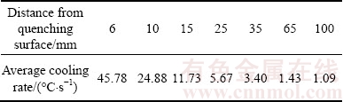
The measured cooling curves at different locations of the modified Jominy specimen during water-spray quenching are shown in Fig. 4 and the calculated average cooling rates at the corresponding locations in quench sensitive temperature range of 7B50 alloy (420-230 ��C) [28,29], are shown in Table 2. It can be seen that the cooling rates decrease sharply with increasing the distance from the quenching surface. As shown in Fig. 4 and Table 2, the temperature at 6 mm from the quenching surface has dropped to 230 ��C after spray quenching only 4.8 s and the calculated average cooling rate in quench sensitive temperature range is as high as 45.78 ��C/s while the average cooling rate in the same temperature range at 100 mm from the quenching surface is only 1.09 ��C/s. The average cooling rate at 6 mm from the quenching surface is higher than that measured by WEN et al [30], XIONG et al [31] and LI et al [2] at 5 mm from the quenching surface of 6061 and 7050 alloys with similar experimental conditions.
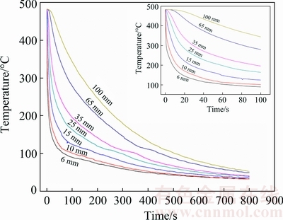
Fig. 4 Measured cooling curves at different locations of modified Jominy specimen
Table 2 Average cooling rates in temperature range of 420- 230��C at different locations of modified Jominy specimen
4.3 Calculation of SSHTC during water-spray quenching
In order to accurately calculate the SSHTC of the quenching surface during water-spray quenching, the thermo-physical properties of 7B50 alloy at any temperature are determined by B-Splines curve interpolation method according to Fig. 3. Based on the measured cooling curves shown in Fig. 4 and the thermo-physical properties of 7B50 alloy in Fig. 3, the initial relationship between the SSHTC and quenching time is obtained using the inverse solution module of the ProCAST software. With the initial SSHTC curve as the heat transfer boundary condition, the calculated cooling curve nearest the quenching surface can be obtained using the direct solution module of the ProCAST software. By comparing the calculated cooling curve with the corresponding measured cooling curve, the initial SSHTC curve is repeatedly modified to ensure that the calculated cooling curve nearest the quenching surface is close to the corresponding measured one. The final relationship between the SSHTC and quenching time during water-spray quenching is shown in Fig. 5.
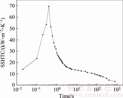
Fig. 5 Relationship between SSHTC and quenching time during water-spray quenching
Then, the data of the SSHTC curve in Fig. 5 are imported to the ProCAST software as the heat transfer boundary condition to calculate the cooling curves at different locations of the specimen. Figure 6 shows the comparison results of the measured (solid line) cooling curves and the corresponding calculated (dash line) cooling curves. It is clear that each calculated cooling curve is very close to the corresponding measured cooling curve. Therefore, the final SSHTC curve of the quenching surface calculated by the ProCAST software with temperature-dependent thermo-physical properties of 7B50 alloy can truly and accurately reveal the characteristics of heat transfer process between the quenching surface and quenching medium during water- spray quenching.
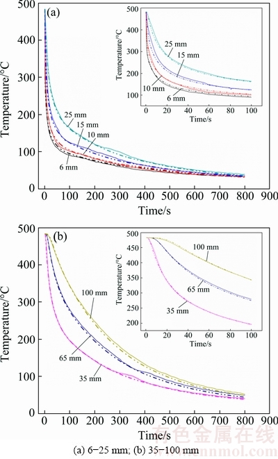
Fig. 6 Comparison results of measured (solid line) and calculated (dash line) cooling curves during water-spray quenching at different locations from quenching surface
According to the SSHTC curve of the quenching surface (Fig. 5), it can be seen that the SSHTC reaches the peak-value of 69 kW/(m2��K) at spray quenching for 0.4 s. After that peak, the value of the SSHTC drops rapidly with increasing the quenching time. For instance, the duration of the SSHTC higher than 50 kW/(m2��K) is less than 0.3 s, with increasing the quenching time to 4 s the value of the SSHTC drops to 15 kW/(m2��K) and prolonging the quenching time over 300 s the value of the SSHTC is stable at 3-6 kW/(m2��K). In the present work, the peak-value of the SSHTC is higher than that (17-50 kW/(m2��K)) reported in Refs. [21,30-33], but the stage of heat transfer with high value of the SSHTC lasts only a few seconds throughout the spray quenching process. The main reason for this phenomenon is that the modified Jominy specimen in the present work has many advantages, including thermocouples accurately installed in the specimen, firmly bonding with the specimen and rapidly responding to temperature variations, which will reduce the influence of temperature hysteresis to the minimum. The installation locations of thermocouples are so close to the quenching surface, resulting in the acquired temperature-time data which can accurately record the heat exchange process near the quenching surface. The acquisition frequency of temperature-time data is high enough to guarantee that the measured cooling curves in the specimen especially near the quenching surface can truly reflect temperature variations in a small interval of quenching time. Therefore, it is reasonable to believe that the calculated SSHTC curve of the quenching surface in present work is more accurate.
When the data of the SSHTC curve in Fig. 5 are used as heat transfer boundary condition, the cooling curve at center point of the quenching surface is obtained, as shown in Fig. 7. The cooling curve expressed by linear coordinates (Fig. 7(a)) shows that the cooling rate on the quenching surface is extremely high in temperature range of 483-160 ��C during water-spray quenching. However, a slight temperature fluctuation appears in temperature range of 160-170 ��C on this cooling curve. Figure 7(b) shows that within 0.5 s of water-spray quenching, temperature of the quenching surface decreases rapidly from 483 to 160 ��C followed by a slight temperature fluctuation at about 0.5 s, which corresponds to the temperature fluctuation in Fig. 7(a).
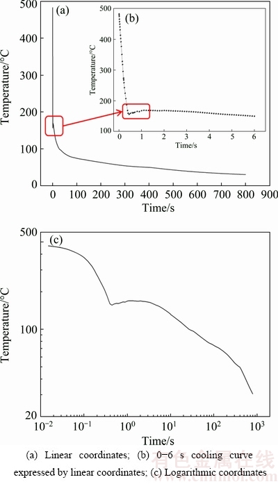
Fig. 7 Calculated cooling curves at center point of quenching surface
Figure 7(c) shows the same cooling curve at center point of the quenching surface expressed by logarithmic coordinates. By comparing Figs. 7(a), (b) and (c), it can be found that the slight temperature fluctuation in Figs. 7(a) and (b) is consistent with the approximate temperature plateau in Fig. 7(c). The temperature plateau appears at 160-170 ��C and lasts about 3 s. XIONG et al [34] also found temperature fluctuations in temperature range of 90-140 ��C at the cooling curves on the quenching surface of the 7050 alloy which were calculated by two different mathematical models. In addition, BUCZEK and TELEJKO [35] observed temperature fluctuations in measured cooling curves at locations of 1.1-4.5 mm from the quenching surface when the brass probes were immersion quenched. For instance, the temperature fluctuation appeared in temperature range of 260-290 ��C and its amplitude was 30 ��C at 1.1 mm from the quenching surface. They thought that the main reason for this temperature fluctuation was the formation and subsequent rupture of steam films on the quenching surface in the initial stage of quenching.
When metal workpieces are immersion quenched in liquid medium, the heat transfer process between quenching surfaces of the workpieces and quenching medium often has four regimes including the film boiling regime, transition boiling regime, nucleate boiling regime and single-phase convective regime. The heat transfer coefficient in film boiling regime and single- phase convective regime is low, while it is middle in transition boiling regime and high in nucleate boiling regime [36,37]. However, the experimental conditions of water-spray quenching and immersion quenching are quite different. In spray quenching process, flow velocity of quenching medium is fast and remains stable ensuring that the quenching surface always keeps close contact with quenching medium. As shown in Fig. 7(b), within 0.5 s of water-spray quenching, temperature of the quenching surface decreases linearly with the increase of the quenching time, furthermore, the cooling rate on the quenching surface is extremely high and almost a constant, indicating that the characteristics of film boiling regime are not obvious in this duration [21,38]. Therefore, in the initial stage of water-spray quenching, the heat transfer process of the quenching surface is dominated by nucleate boiling regime. Subsequently, with the quenching time over 0.5 s, the cooling rate on the quenching surface drops sharply. As shown in Fig. 7(c), the temperature plateau at 160-170 ��C starts at about spray quenching for 0.5 s which coincides with the SSHTC sharp decrease from its peak-value (at spray quenching for 0.4 s), resulting in a sudden decrease of the heat flux flowing out from the quenching surface. Therefore, the heat transfer mechanism of the quenching surface transforms from nucleate boiling regime to single-phase convective regime during the temperature plateau. However, the above complex transformation process spends less than 1 s. In such a short time, temperature of the most parts inside the specimen is still at solid solution temperature, leading to a huge temperature gradient along the axial direction of the specimen. Fourier law of one-dimensional heat transfer process shows that the heat flux is proportional to temperature gradient in the specimen and the thermal conductivity of material. In the initial stage of quenching, the heat flux flows out from the quenching surface to quenching medium sharply decreasing to a small value while it flows into the quenching surface from internal parts of the specimen maintaining at a high value due to the large temperature gradient perpendicular to the quenching surface. With temperature of the quenching surface decreasing to a certain value, the heat flux flowing out and into the quenching surface will maintain a dynamic balance for a short period, which is the reason for the phenomenon called temperature plateau.
After the temperature plateau, temperature gradient between the quenching surface and internal parts of the specimen gradually decreases to a small value. When the heat flux flowing out from the quenching surface is more than that from the internal parts to the quenching surface, temperature of the quenching surface will decrease again. At this moment, the heat transfer mechanism of the quenching surface has transformed to single-phase convective regime. Therefore, variation tendency of the cooling curve at center point of the quenching surface is shown in Fig. 7 during water-spray quenching process.
Figure 8 shows the relationship between the SSHTC and temperature of the quenching surface. It is found that the value of the SSHTC firstly increases rapidly with decreasing the temperature of the quenching surface until to the peak-value. As an example, the value of the SSHTC increases from 0 at 483 ��C to its the peak-value of 69 kW/(m2��K) at 160 ��C. Subsequently, the temperature plateau appears on the cooling curve at center point of the quenching surface, leading to a sharp drop of the SSHTC in a slight temperature fluctuation of the quenching surface, which can be attributed to the rapid transformation of the heat transfer mechanism of the quenching surface from nucleate boiling regime to single-phase convective regime. For instance, the SSHTC decreases from the peak-value of 69 down to 15 kW/(m2��K) when temperature of the quenching surface slightly decreases from 160 to 150 ��C. With further decreasing temperature of the quenching surface, the SSHTC decreases slowly, which results from the fact that the heat transfer mechanism of the quenching surface has been in stable single-phase convective regime.
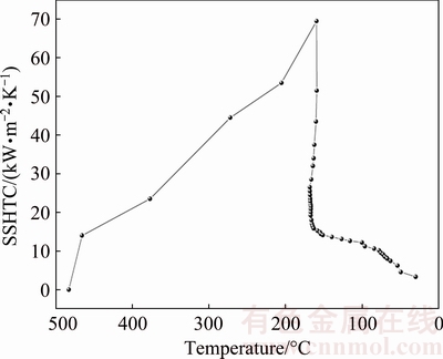
Fig. 8 Relationship between SSHTC and temperature at center point of quenching surface
5 Conclusions
1) The accurate cooling curves of 7B50 alloy were measured by the modified Jominy specimen during water-spray quenching. The average cooling rates at 6 and 100 mm from the quenching surface are 45.78 and 1.09 ��C/s, respectively, in quench sensitive temperature range of 420-230 ��C.
2) The SSHTC of the quenching surface changes rapidly with increasing the quenching time and reaches the peak-value of 69 kW/(m2��K) at spray quenching for 0.4 s. The duration of the SSHTC higher than 50 kW/(m2��K) is less than 0.3 s, with increasing the quenching time to 4 s, the SSHTC decreases to 15 kW/(m2��K), and prolonging the quenching time over 300 s the SSHTC is stable at 3-6 kW/(m2��K).
3) In the initial stage of water-spray quenching, the phenomenon called temperature plateau appears on the cooling curve at center point of the quenching surface. The temperature range of this plateau is 160-170 ��C and the plateau lasts for about 3 s. During the temperature plateau, the heat transfer mechanism of the quenching surface transforms from nucleate boiling regime to single-phase convective regime.
4) During water-spray quenching, with temperature of the quenching surface decreasing to 160 ��C, the SSHTC of the quenching surface reaches its peak-value. Subsequently, with temperature of the quenching surface decreasing from 160 to 150 ��C, the SSHTC rapidly decreases from 69 to 15 kW/(m2��K).
References
[1] ZHANG Y H, YANG S C, JI H Z. Microstructure evolution in cooling process of Al-Zn-Mg-Cu alloy and kinetics description [J]. Transactions of Nonferrous Metals Society of China, 2012, 22(9): 2087-2091.
[2] LI P Y, XIONG B Q, ZHANG Y A, LI Z H, ZHU B H, WANG F, LIU H W. Quench sensitivity and microstructure character of high strength AA7050 [J]. Transactions of Nonferrous Metals Society of China, 2012, 22(2): 268-274.
[3] DURSUN T, SOUTIS C. Recent developments in advanced aircraft aluminium alloys [J]. Materials and Design, 2014, 56(4): 862-871.
[4] HEINZ A, HASZLER A, KEIDEL C, MOLDENHAUER S, BENEDICTUS R, MILLER W S. Recent development in aluminium alloys for aerospace applications [J]. Materials Science and Engineering A, 2000, 280(1): 102-107.
[5] LIU S D, ZHONG Q M, ZHANG Y, LIU W J, ZHANG X M, DENG Y L. Investigation of quench sensitivity of high strength Al-Zn-Mg-Cu alloys by time-temperature-properties diagrams [J]. Materials and Design, 2010, 31(6): 3116-3120.
[6] ROMETSCH P A, ZHANG Y, KNIGHT S. Heat treatment of 7xxx series aluminium alloys��Some recent developments [J]. Transactions of Nonferrous Metals Society of China, 2014, 24(7): 2003-2017.
[7] ROBINSON J S, TANNER D A, TRUMAN C E, PARADOWSKA A M, WIMPORY R C. The influence of quench sensitivity on residual stresses in the aluminium alloys 7010 and 7075 [J]. Materials Characterization, 2012, 65(3): 73-85.
[8] YANG X W, ZHU J C, NONG Z S, LAI Z H, HE D. FEM simulation of quenching process in A357 aluminum alloy cylindrical bars and reduction of quench residual stress through cold stretching process [J]. Computational Materials Science, 2013, 69(1): 396-413.
[9] TANNER D A, ROBINSON J S. Effect of precipitation during quenching on the mechanical properties of the aluminium alloy 7010 in the W-temper [J]. Journal of Materials Processing Technology, 2004, 153-154(22): 998-1004.
[10] SUGIANTO A, NARAZAKI M, KOGAWARA M, SHIRAYORI A. A comparative study on determination method of heat transfer coefficient using inverse heat transfer and iterative modification [J]. Journal of Materials Processing Technology, 2009, 209(10): 4627-4632.
[11] MAHONEY D O, BROWNE D J. Use of experiment and an inverse method to study interface heat transfer during solidification in the investment casting process [J]. Experimental Thermal and Fluid Science, 2000, 22(3-4): 111-122.
[12] RAUDENSKY M. Heat transfer coefficient estimation by inverse conduction algorithm [J]. International Journal of Numerical Methods for Heat and Fluid Flow, 1993, 3(3): 257-266.
[13] FAN C L, SUN F R, YANG L. A numerical method on inverse determination of heat transfer coefficient based on thermographic temperature measurement [J]. Chinese Journal of Chemical Engineering, 2008, 16(6): 901-908.
[14] NARAZAKI M, KOGAWARA M, QIN M, WATANABE Y. Measurement and database construction of heat transfer coefficients of gas quenching [J]. Journal of Mechanical Engineering, 2009, 55(3): 167-173.
[15] CHEN H T, HSU W L. Estimation of heat transfer coefficient on the fin of annular-finned tube heat exchangers in natural convection for various fin spacings [J]. International Journal of Heat and Mass Transfer, 2007, 50(9-10): 1750-1761.
[16] NIKOLIC Z S, YOSHIMURA M, ARAKI S, FUJIWARA T. Finite difference method for computer study of the interfacial heat transfer coefficient during rapid solidification of spherical samples on a metallic substrate [J]. Science of Sintering, 2007, 39(2): 111-116.
[17] ONYANGO T T M, INGHAM D B, LESNIC D. Reconstruction of heat transfer coefficients using the boundary element method [J]. Computers and Mathematics with Applications, 2008, 56(1): 114-126.
[18] ONYANGO T T M, INGHAM D B, LESNIC D. Inverse reconstruction of boundary condition coefficients in one-dimensional transient heat conduction [J]. Applied Mathematics and Computation, 2009, 207(2): 569-575.
[19] SABLANI S S, KACIMOV A, PERRET J, MUJUMDAR A S, CAMPO A. Non-iterative estimation of heat transfer coefficients using artificial neural network models [J]. International Journal of Heat and Mass Transfer, 2005, 48(3-4): 665-679.
[20] XIAO B W, WANG Q G, JADHAV P, LI K Y. An experimental study of heat transfer in aluminum castings during water quenching [J]. Journal of Materials Processing Technology, 2010, 210(14): 2023-2028.
[21] XU R, LI L X, ZHANG L Q, ZHU B W, LIU X, BU X B. Influence of pressure and surface roughness on the heat transfer efficiency during water spray quenching of 6082 aluminum alloy [J]. Journal of Materials Processing Technology, 2014, 214(12): 2877-2883.
[22] ULYSSE P, SCHULTZ R W. The effect of coatings on the thermo-mechanical response of cylindrical specimens during quenching [J]. Journal of Materials Processing Technology, 2008, 204(1-3): 39-47.
[23] LI H P, ZHAO G Q, HUANG C Z, NIU S T. Technological parameters evaluation of gas quenching based on the finite element method [J]. Computational Materials Science, 2007, 40(2): 282-291.
[24] KANG Lei, ZHAO Gang, TIAN Ni, LIU Kun. Research on a new method of axial temperature field determination during aluminum alloy end quenching [J]. Light Alloy Fabrication Technology, 2013, 41(10): 45-49. (in Chinese)
[25] NEWKIRK J W, MACKENZIE D S. The Jominy end quench for light-weight alloy development [J]. Journal of Materials Engineering and Performance, 2000, 9(4): 408-415.
[26] FRANCO F A, GONZALEZ M F R, CAMPOS M F D, PADOVESE L R. Relation between magnetic Barkhausen noise and hardness for Jominy quench tests in SAE 4140 and 6150 steels [J]. Journal of Nondestructive Evaluation, 2013, 32(1): 93-103.
[27] CAKIR M, OZSOY A. Investigation of the correlation between thermal properties and hardenability of Jominy bars quenched with air-water mixture for AISI 1050 steel [J]. Materials and Design, 2011, 32(5): 3099-3105.
[28] ZHANG Xin-ming, LIU Wen-jun, LIU Sheng-dan, YUAN Yu-bao, DENG Yun-lai. TTP curve of aluminum alloy 7050 [J]. The Chinese Journal of Nonferrous Metals, 2009, 19(5): 861-868. (in Chinese)
[29] LI Pei-yue, XIONG Bai-qing, ZHANG Yong-an, LI Zhi-hui, ZHU bao-hong, WANG Feng, LIU Hong-wei. Hardenability characteristic and microstructure of 7050 Al alloy [J]. The Chinese Journal of Nonferrous Metals, 2011, 21(3): 513-521. (in Chinese)
[30] WEN Liu, LIU Lu-lu, GAO Meng, PAN Xue-zhu, WANG Ying-xin, CHEN Bin, WANG Meng-jun. Surface heat transfer coefficient of 6061 aluminum alloy during quenching [J]. Heat Treatment of Metals, 2011, 36(10): 59-62. (in Chinese)
[31] XIONG Chuang-xian, DENG Yun-lai, ZHANG Jin, ZHANG Xin-ming. Thermal simulation on surface heat transfer coefficient during quench of 7050 Al alloy by water spraying [J]. Materials Science and Engineering of Powder Metallurgy, 2010, 15(5): 421-426. (in Chinese)
[32] DENG Yun-lai, GUO Shi-gui, XIONG Chuang-xian, ZHANG Xin-ming. Effect of water spraying parameters on heat transfer coefficient of 7050 aluminum alloy during quench [J]. Journal of Aeronautical Materials, 2010, 30(6): 21-26. (in Chinese)
[33] CHEN Bin, GAO Meng, WEN Liu, PAN Xue-zhu, WANG Ying-xin, WANG Meng-jun. Experiment and finite element simulation of online quenching process for 6063 aluminum alloy [J]. Light Alloy Fabrication Technology, 2012, 40(3): 55-59. (in Chinese)
[34] XIONG Chuang-xian, DENG Yun-lai, CAO Sheng-qiang, ZHANG Xin-ming. Compared two methods of inverse heat transfer coefficient for thick-plate quenching [J]. Heat Treatment of Metals, 2011, 36(12): 112-117. (in Chinese)
[35] BUCZEK A, TELEJKO T. Inverse determination of boundary conditions during boiling water heat transfer in quenching operation [J]. Journal of Materials Processing Technology, 2004, 155-156(6): 1324-1329.
[36] YANG Shi-ming, TAO Wen-quan. Heat transfer [M]. 3rd ed. Beijing: Higher Education Press, 1998. (in Chinese)
[37] YU Jing-lu, WEI Ji-he. Heat and mass transfer in metallurgy [M]. Beijing: Metallurgical Industry Press, 1981. (in Chinese)
[38] XU F C, GADALA M S. Heat transfer behavior in the impingement zone under circular water jet [J]. International Journal of Heat and Mass Transfer, 2006, 49(21-22): 3785-3799.
7B50����ǿ���Ͻ���ˮ�������ۺϱ��滻��ϵ���ļ���
�� ��1���� ��1���� ��1���ź���2
1. ������ѧ ���Ͽ�ѧ�빤��ѧԺ ���ϸ���������֯���������ص�ʵ���ң����� 110819��
2. ������ѧ ���Ͽ�ѧ�빤��ѧԺ ���ϵ�Ź����о��������ص�ʵ���ң����� 110819
ժ Ҫ�����øĽ���Jominy��Ʒ��ȷ�ⶨ7B50�Ͻ�����ˮ���ʱ��Ʒ�ڲ����¶ȳ�(��ȴ����)�������� JMatPro�������7B50�Ͻ������Բ������¶ȵı仯��ϵ���Է�����ԭ��Ϊ����������ProCAST����Ԫ��������õ���ˮ���ʱ��������ۺϱ��滻��ϵ���ı仯���ɡ������������ˮ���ʱ���������6 mm������������¶�����(420~230 ��C)�ڵ�ƽ����ȴ����Ϊ45.78 ��C/s����ˮ���ʼ0.4 sʱ���ۺϱ��滻��ϵ���ﵽ��ֵ69 kW/(m2��K)����ʱ��Ӧ�Ĵ������¶�Ϊ160 ��C����ˮ�����ڣ����������ĵ���ȴ�����ϳ��֡��¶�ƽ̨������ƽ̨��Ӧ���¶ȷ�ΧΪ160~170 ��C������ʱ��ԼΪ3 s�����¶�ƽ̨�����ڼ䣬������Ļ��Ȼ��ƴӺ�̬���ڽ�ת��Ϊ�������ȽΡ�
�ؼ��ʣ�7B50���Ͻ𣻱�����ˮ��𣻷�����ԭ�����ۺϱ��滻��ϵ������ȴ����
(Edited by Wei-ping CHEN)
Foundation item: Project (2016YFB0300801) supported by the National Key Research and Development Program of China; Project (51371045) supported by the National Natural Science Foundation of China
Corresponding author: Gang ZHAO; Tel: +86-24-83691567; E-mail: zhaog@mail.neu.edu.cn
DOI: 10.1016/S1003-6326(18)64735-1
Abstract: According to inverse heat transfer theory, the evolutions of synthetic surface heat transfer coefficient (SSHTC) of the quenching surface of 7B50 alloy during water-spray quenching were simulated by the ProCAST software based on accurate cooling curves measured by the modified Jominy specimen and temperature-dependent thermo-physical properties of 7B50 alloy calculated using the JMatPro software. Results show that the average cooling rate at 6 mm from the quenching surface and 420-230 ��C (quench sensitive temperature range) is 45.78 ��C/s. The peak-value of the SSHTC is 69 kW/(m2��K) obtained at spray quenching for 0.4 s and the corresponding temperature of the quenching surface is 160 ��C. In the initial stage of spray quenching, the phenomenon called ��temperature plateau�� appears on the cooling curve of the quenching surface. The temperature range of this plateau is 160-170 ��C with the duration about 3 s. During the temperature plateau, heat transfer mechanism of the quenching surface transforms from nucleate boiling regime to single-phase convective regime.
